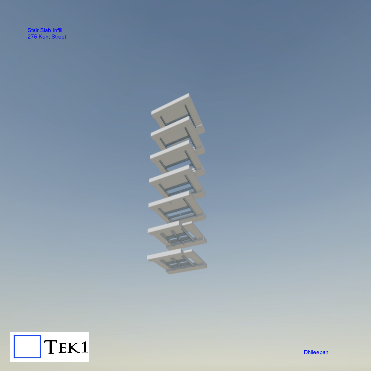
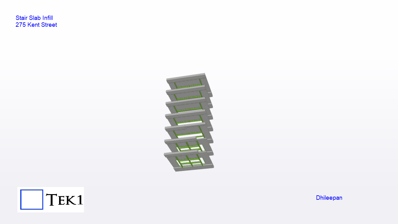
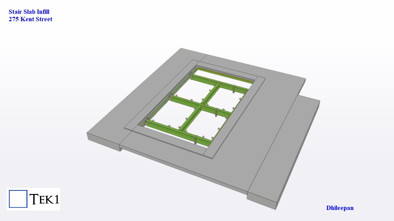
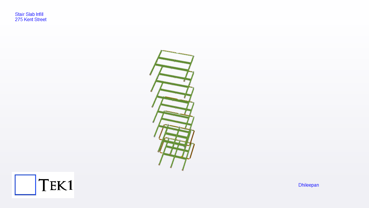
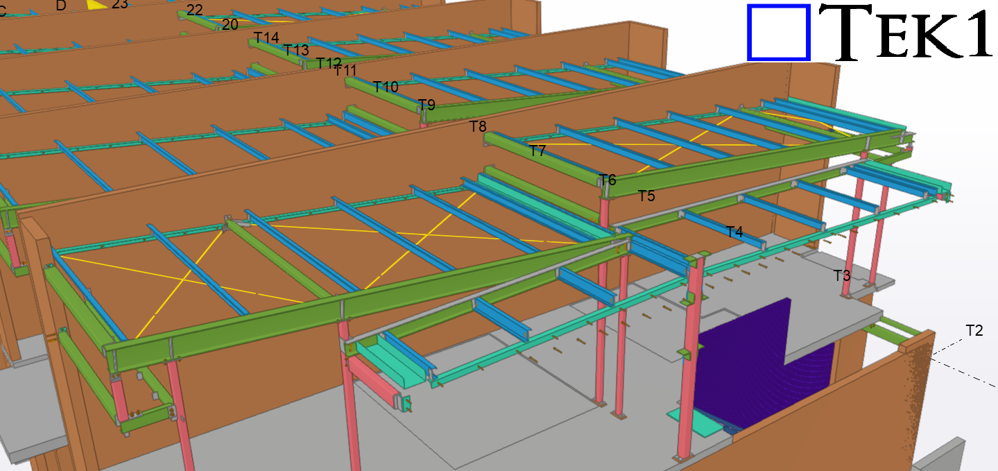
The stairwell at 275 Kent Street had been demolished, leaving open slab areas that needed to be closed. Our task was to support these closures with meticulously detailed steel beams. Following a comprehensive site survey, we supplied steel beams tailored to different levels.
Initially, the project scope included orders for only three levels. However, after completing these, four additional levels were incorporated to fully close the openings.
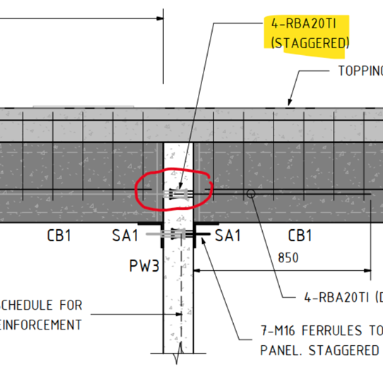
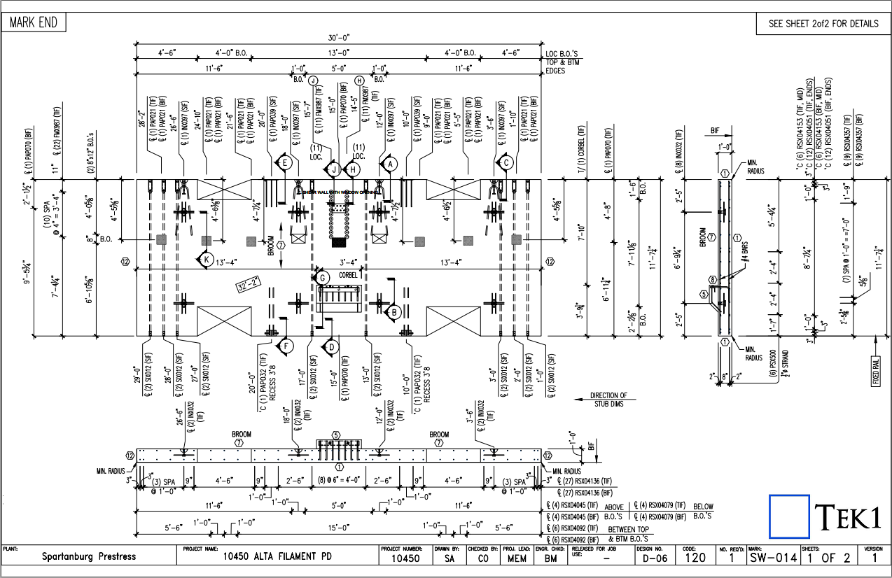
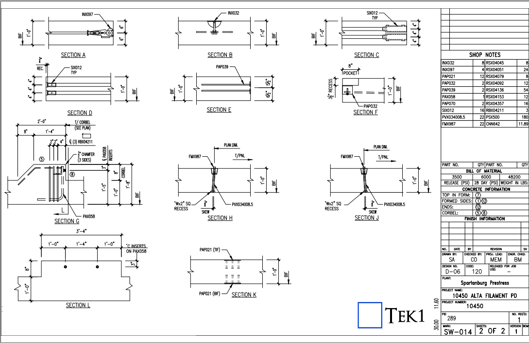
In one of our Projects, Audi Centre Myaree for the Client PARKD Ltd, the typical structural drawing detail represents the precast wall panel which connects to the Delta core slab with RBA20TI inserts.
Two variations of Precast panel thickness have been used in this project: 150thk, and 200thk.
What is the Problem?
The Insert component RBA20TI or PTI20 are difficult to place on the precast panel face with a wall thickness of 150mm.
Cause for the Problem: Lack of minimum concrete cover is due to component length close to the Panel thickness.
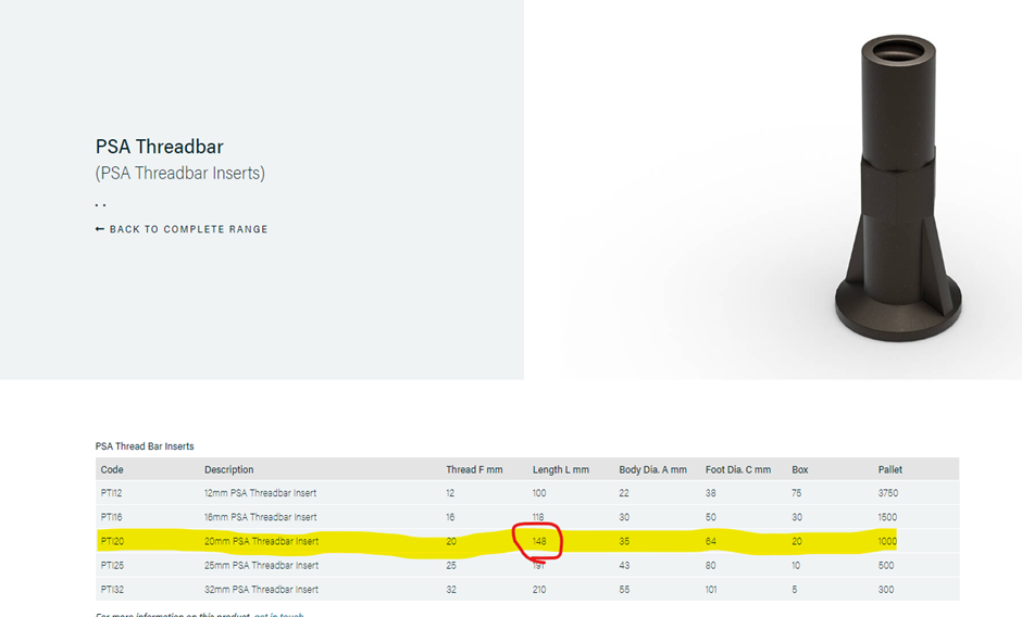
The length of PSA Thread bar Inserts PTI20 is 148mm as per the PSA Schedule.
The minimum concrete cover required for this project is 30mm. However, placing the component with a height of 148mm on a Panel with a thickness of 150mm results in no space for concrete cover, as shown below in Image 1
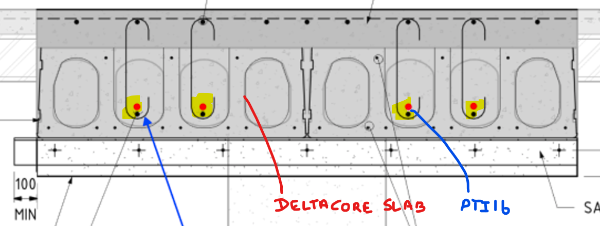
Image 1: Plan View of 150thk Precast Panel with PTI20 Inserts on the panel face.
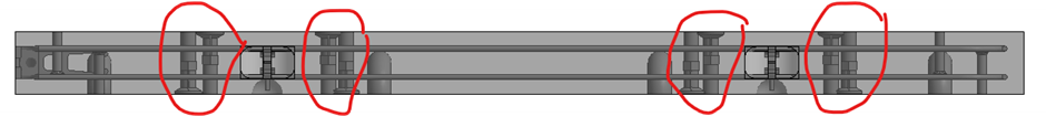
Image 2: 3D view of a 150thk precast panel with PTI20 Insert. The highlighted portion in blue indicates a lack of concrete cover.
3D Model Viewer Link for 150thk Precast Panel with PTI20 Insert:
To retain the 30mm concrete cover in the Precast panel, the PTI20 insert component needs to be replaced with PTI16, which has a length of 118mm. This will result in a 32mm concrete cover, satisfying the minimum cover criteria.
Image 3: Plan View of 150thk Precast Panel with PTI16 Inserts on the panel face.
Image 4: Elevation View of 150 thk panel with PTI16 Insert.
Critical Condition To be Remeber:
Although changing the insert size from PTI120 to PTI16. It is highly required to consider the structural strength of the connection.
The structural strength of PTI16 with starter bars of 16 Ø is lower than that of PTI20 with starter bars of 20 Ø.
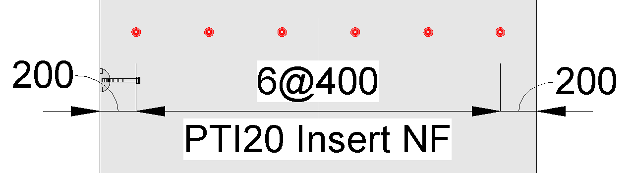
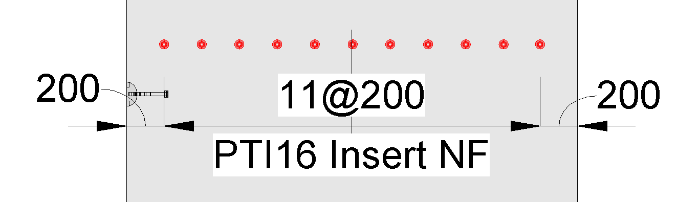
To overcome this, it is advisable to increase the count of PTI16 insets by reducing their spacing compared to the spacing provided for the PTI20 insert.
Image 5: PTI20 insert with a spacing of 400 centers
Image 6: PTI16 insert with a spacing of 200 centers (The ferrule count increased to tally the structural strength)
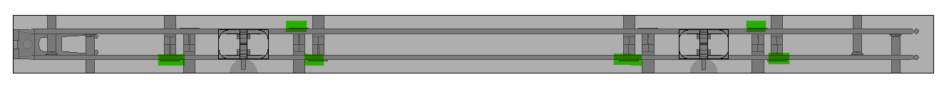
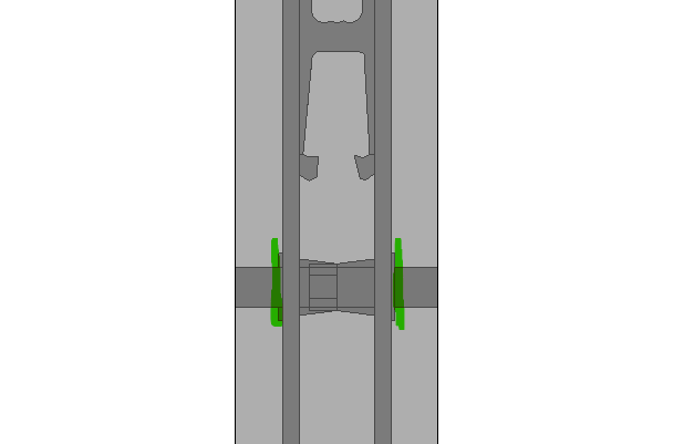
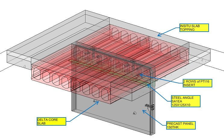
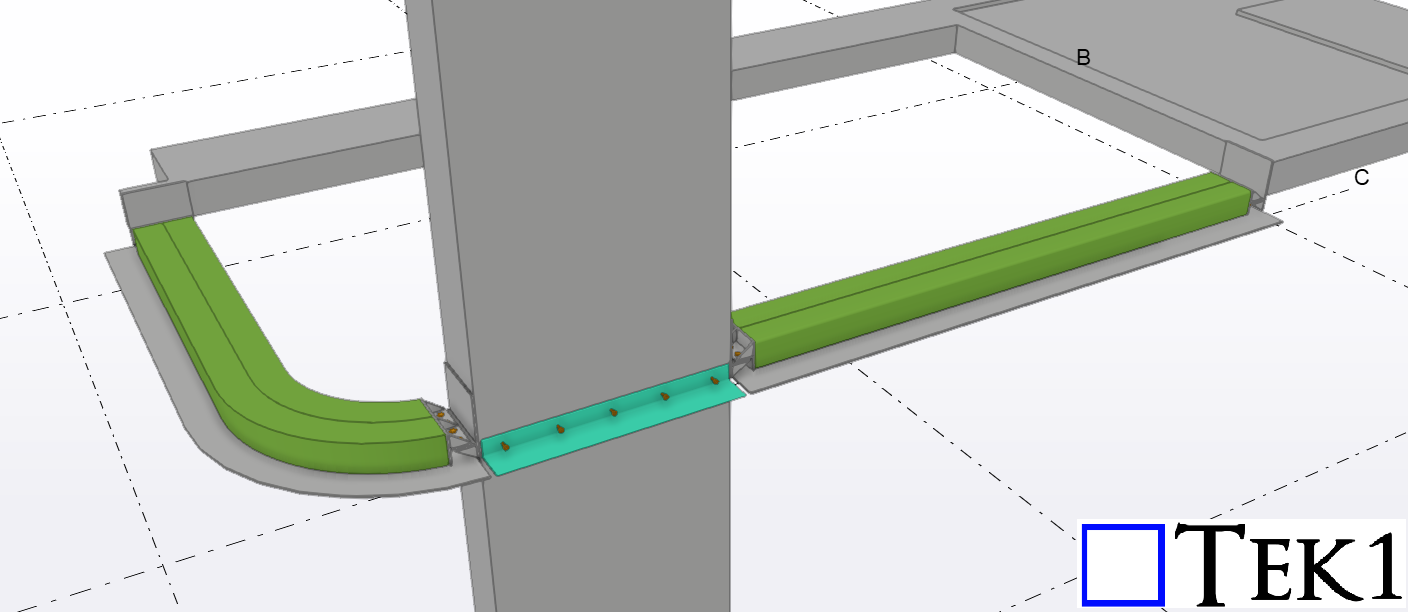
But in our case, since we are using inserts over the Delta Core slab, two rows of PTI16 inserts with a spacing of 150mm are to be placed vertically on the Precast Panel, as shown below
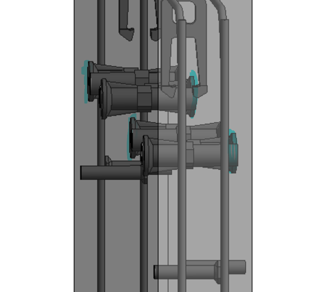
Image 7: Detla Cover connects with the 16Ø Starter bars
Image 8: 3D View of Precast Panel with delta Core
3D Model Viewer Link for Precast Panel with Delta core Connection:
Length of Castin components such as Inserts and Ferrule, needs to be considered about the concrete cover and Panel thickness
If the type of insert or ferrule changes, say from PTI20 to PTI16, to reduce its height, it is mandatory to increase the component count to maintain the structural strength.
Thanks to Robin Hur, Structural Engineer and Project Coordinator from PARKD Ltd, for the support and critical suggestions.
The problem is that concrete is almost never poured correctly. It is never correct.
If your dimension and cut beams to concrete as a reference point, that means all your dimensions will be wrong – because the concrete is NEVER where you expect it to me.
What should you do?
People agree to work to grid lines as reference points. You must dimension to gridlines – unless this is not applicable.
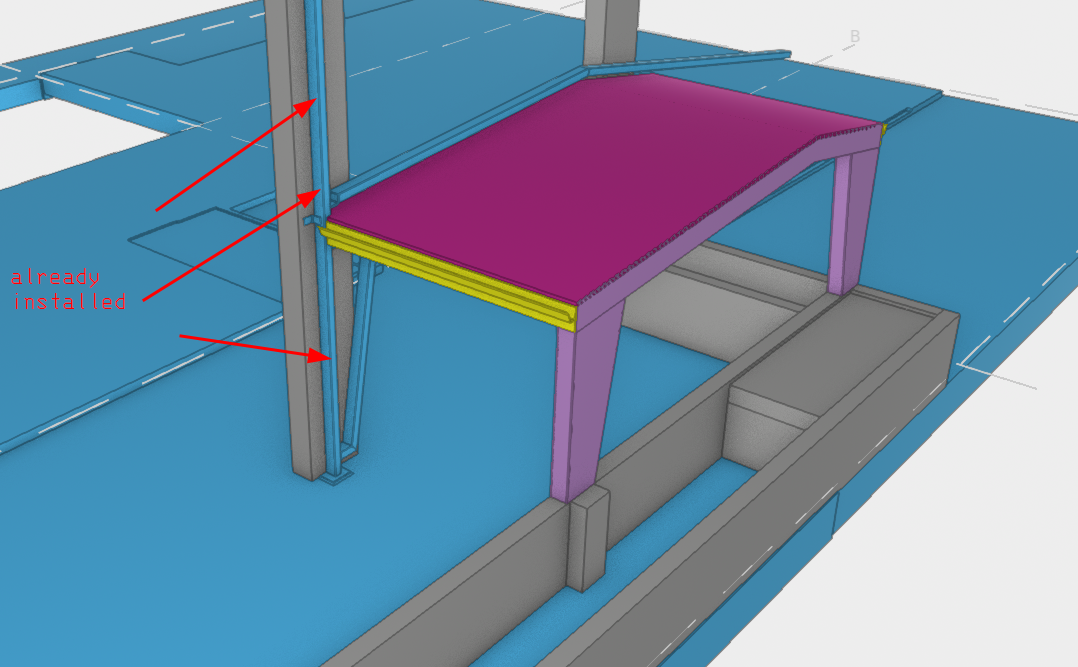
Gridlines are typically not applicable when your steel ties into another structure (e.g. steel or to concrete). If it does, as in this case:
Get a site measurement of where the existing structure is: and use that as a reference.
But what you must never do is to dimension to an arbitrary structure without a site measurement.
What happened in this case?
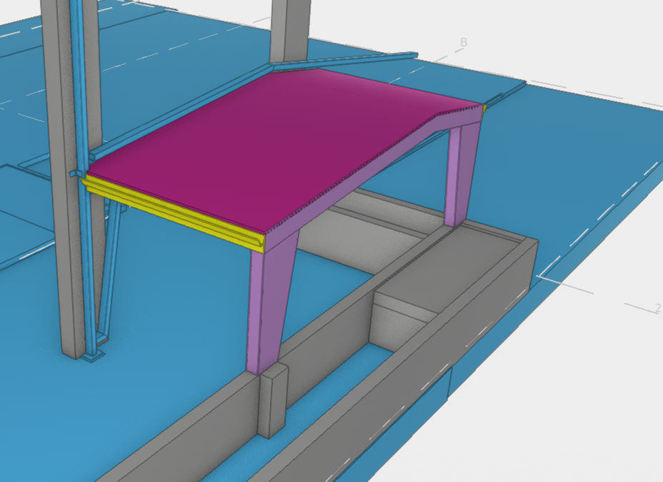
In this case there was something already installed up against the concrete. So we must dimension everything to what is actually installed.
What happens if I dimension to concrete?
This means that your beams will not fit on site.
Which means you’ll get a very angry client: you will cost your client time and money.
This means your name and reputation will go down: clients will not want to deal with both you and our firm.
Summary:
What should I do?
Always make references to GRID LINES, not concrete or steel UNLESS you have a site measurement.
Never dimension to something upon which you do not know the location.
As a steel detailer working on projects for public access areas or residential buildings, you must be familiar with the essential standards to ensure safety and compliance.
In this blog post, we’ll delve into the significance of following standards, with a specific focus on AS1428, AS1657, and BCA, through a real-world case study near the iconic Melbourne Cricket Ground (MCG).
The Case of the Handrails Near MCG
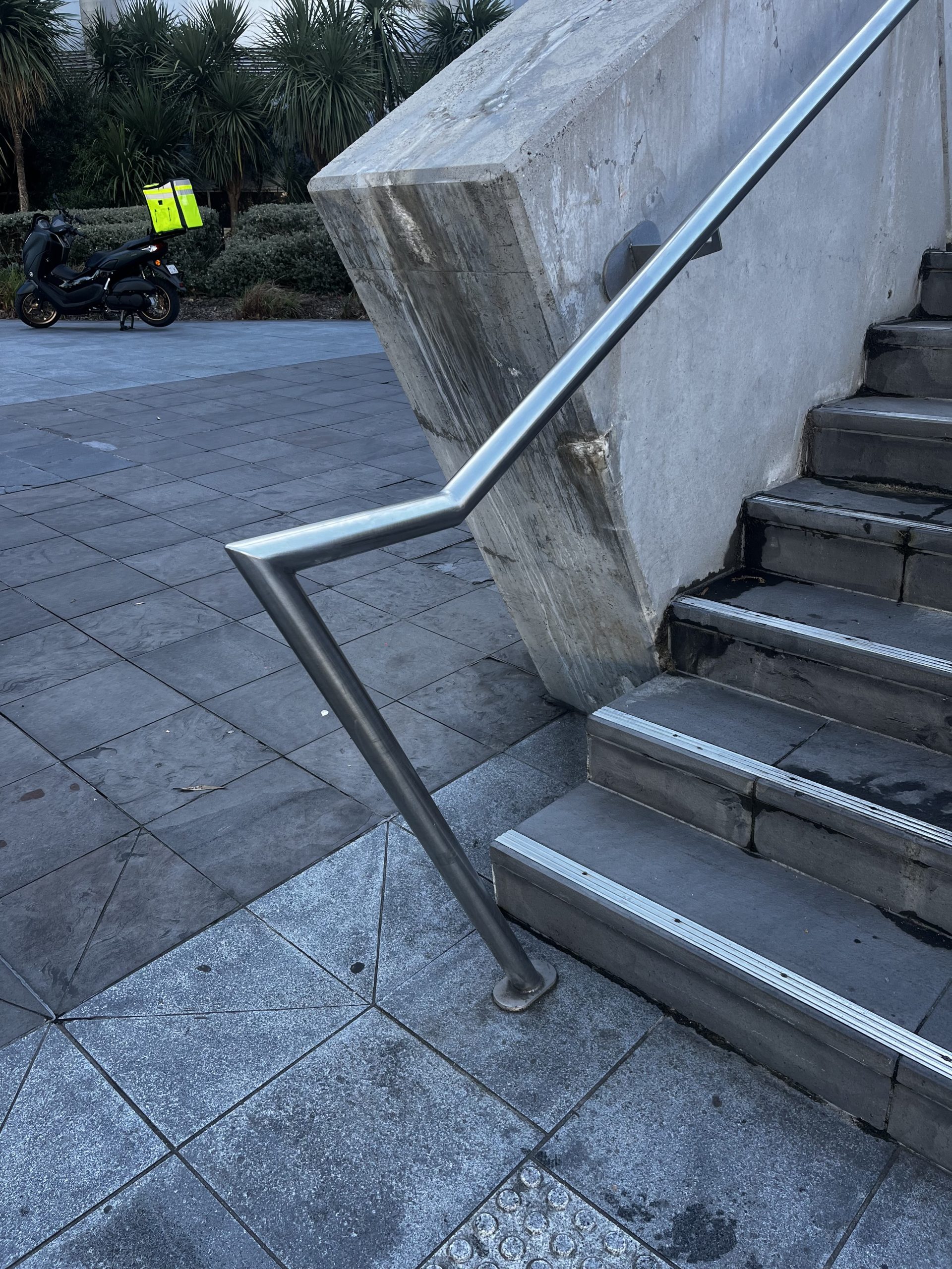
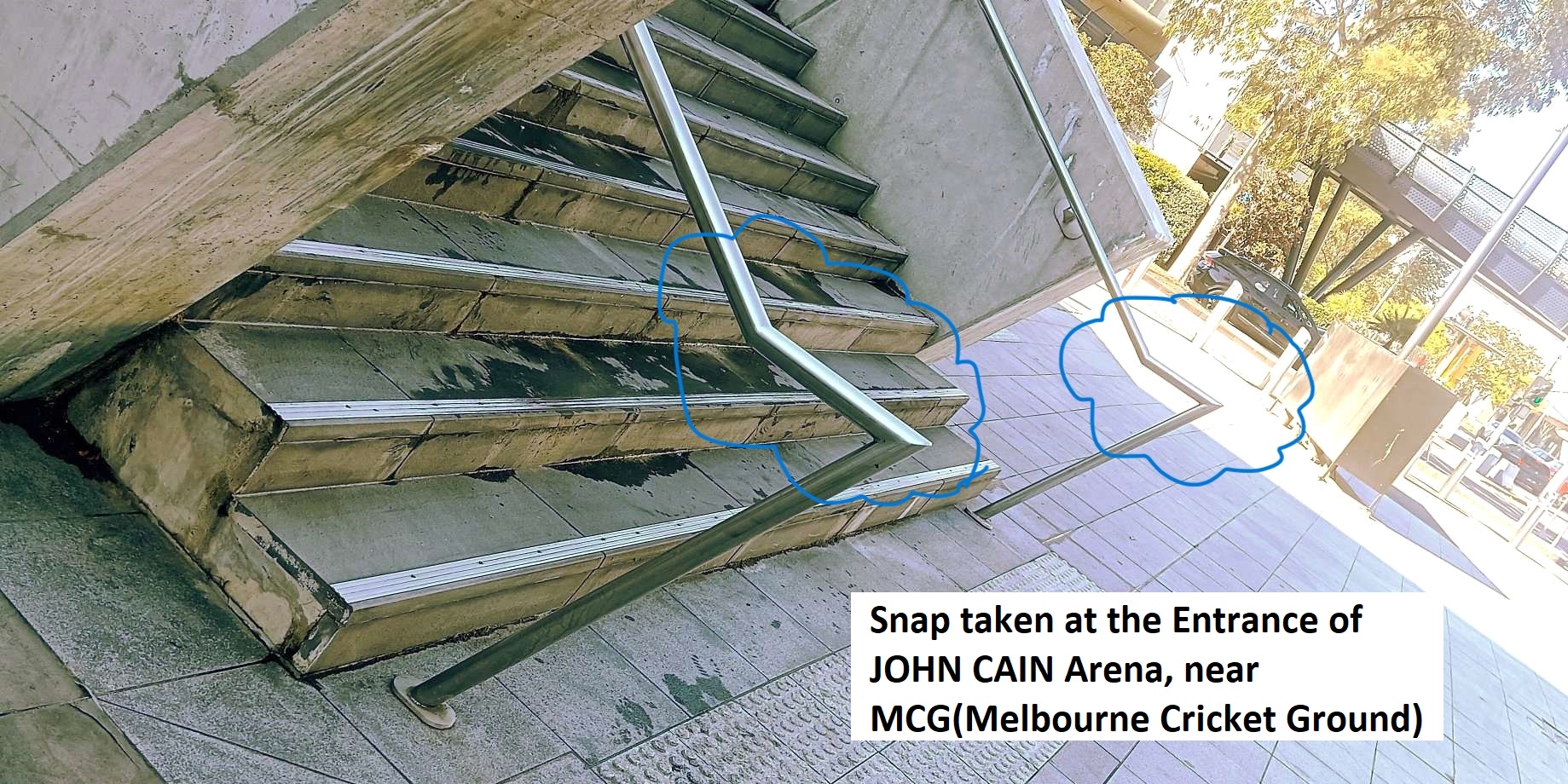
During a recent visit to the vicinity of the Melbourne Cricket Ground, I observed that the installed stair handrail did not meet the compliance as specified in AS1428. The end handrail protrudes with sharp edges, causing safety issues for the public.
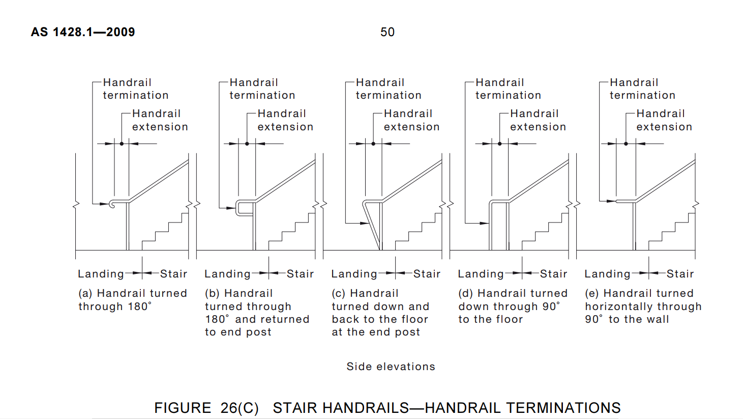
Please refer to the snapshot below, taken at the entrance of JOHN CAIN Arena, Near MCG. Additionally, we have attached another snapshot that refers to the standard handrail which needs to be used in public areas.
Conclusion
Understanding the Standards: AS1428, AS1657, and BCA Before commencing any detailing project, it’s crucial to have a comprehensive understanding of the relevant standards. AS1428 covers design for access and mobility, providing guidelines for elements such as handrails, ramps, and doorways to ensure accessibility for all individuals. AS1657 specifies requirements for fixed platforms, walkways, stairways, and ladders, emphasizing safety and structural integrity. Meanwhile, the Building Code of Australia (BCA) sets forth regulations governing construction, including provisions for structural adequacy and fire safety.
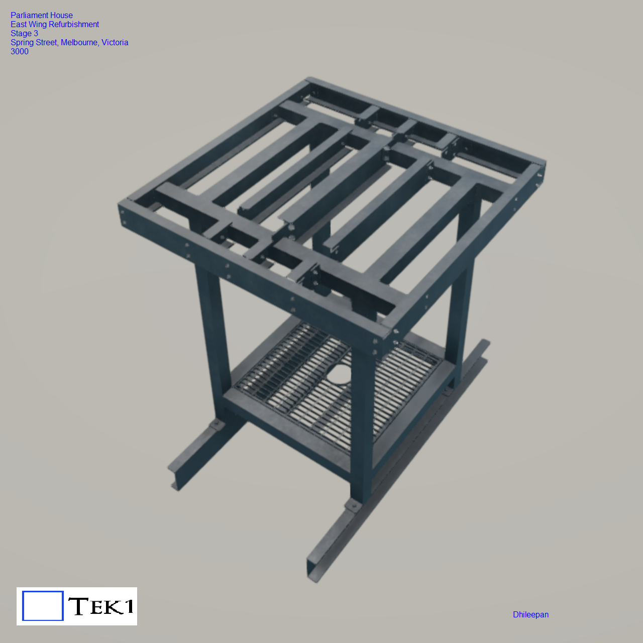
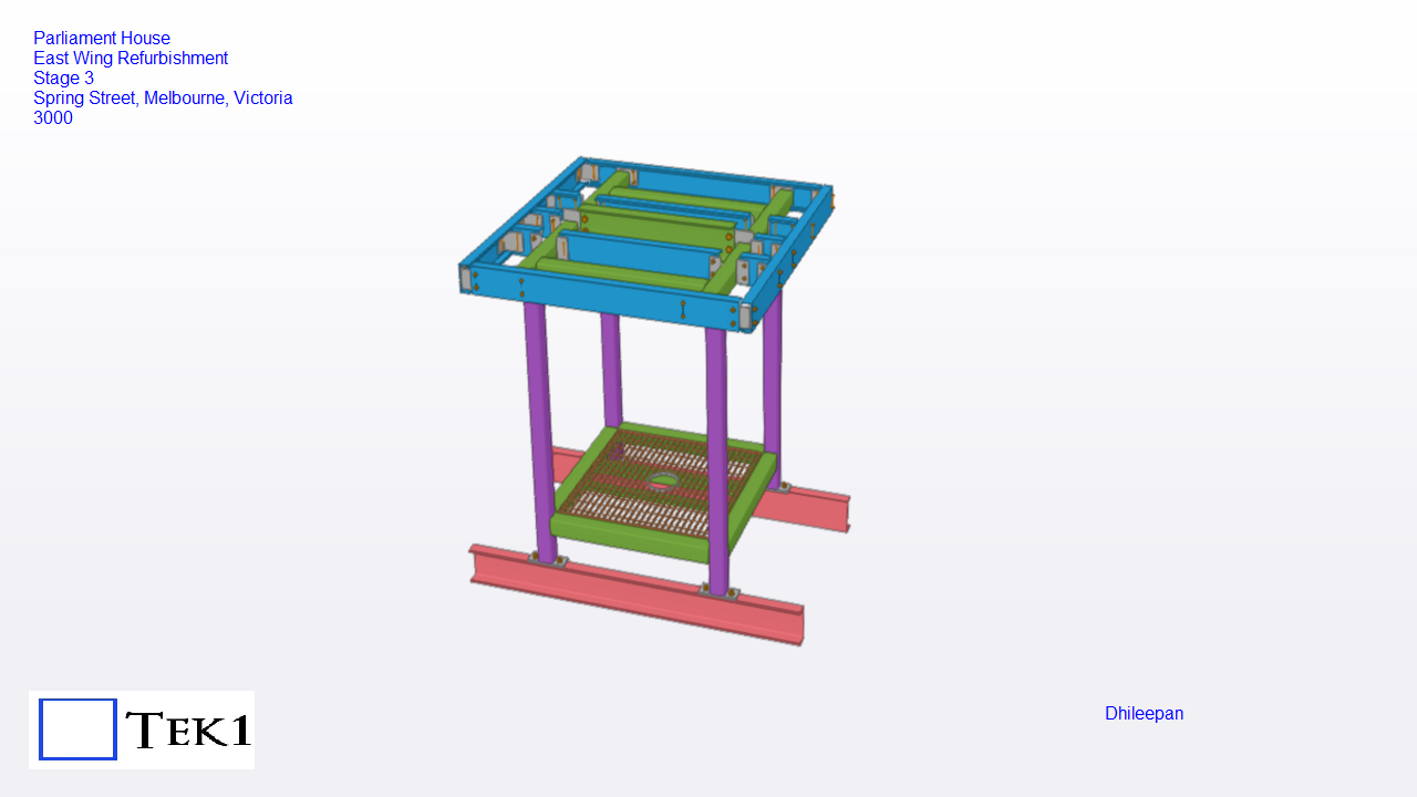
A small lantern has been added to the east wing of the parliament house. Despite its modest size, we take great pride in having contributed to such a prestigious project.
The assembly consists of a single frame with welded columns, positioned atop existing beams. Prior to project commencement, TEK1 provided a detailed sketch outlining the necessary site measurements. With this, we were able to guidance the erection of the lantern for the parliament house accurately and seamlessly.
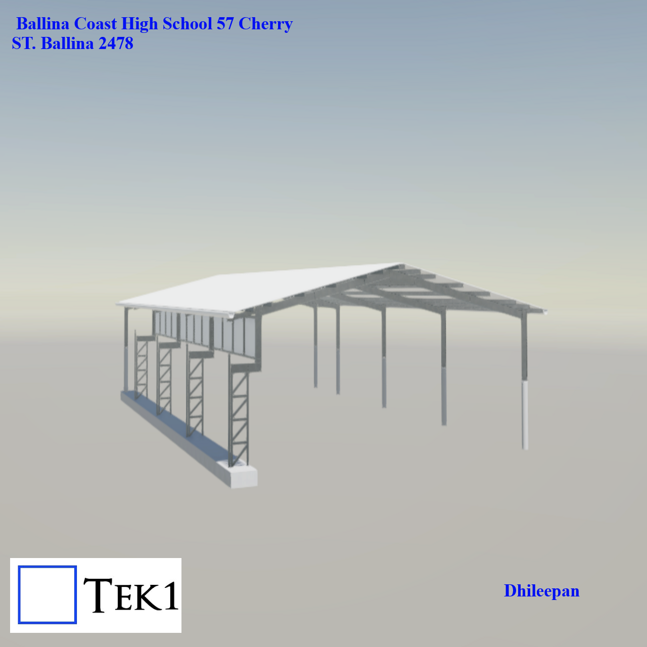
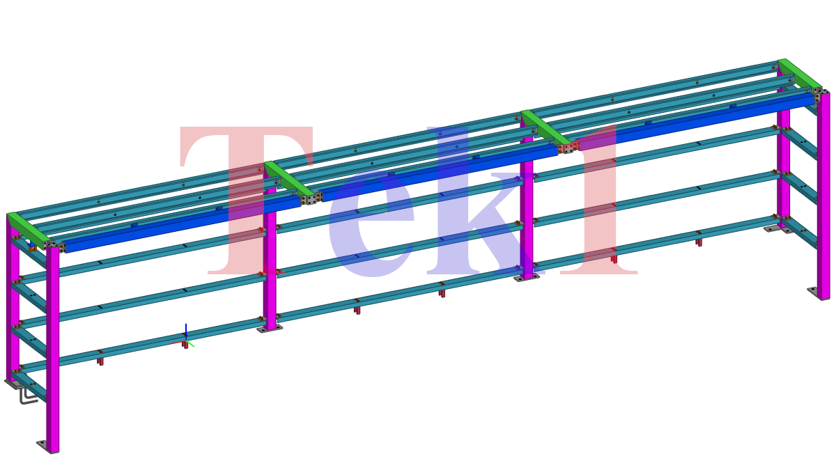
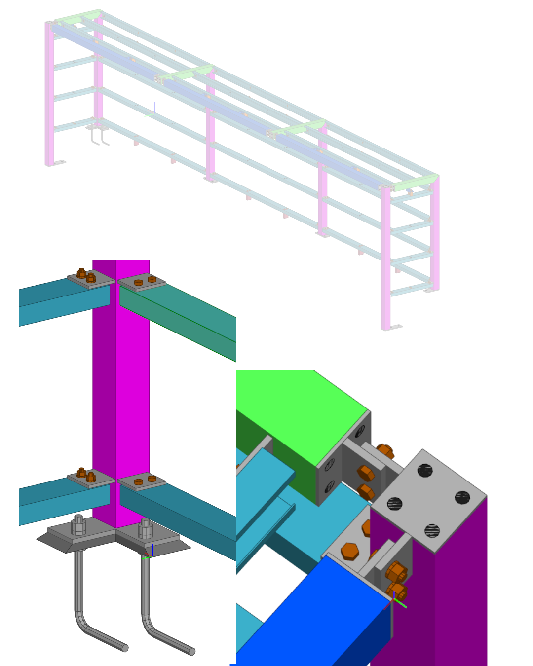
A new outdoor basket ball court has been added adjacent to the existing building in the Ballina High School. The roof design is similar to a warehouse.
Ballania School | NSW
A new outdoor basket ball court has been added adjacent to the existing building in the Ballina High School 57, Cherry Street, Balliana, NSW 2478