Key links:
Please supply checklist and special notes with every take off report you complete.
What is the purpose of an MTO?
- The purpose is to enable our client to quote on a job. These structural steel jobs are expensive, ranging between $2m – 30m dollars. They employ us to do a “take off” i.e. to count the steel elements to enable them to quote, accurate.
- If you make a mistake, then you could potentially cost our client millions of dollars. It is especially important that you DO NOT miss anything which should be in your take off.
- Clients typically price their job based on tonnage of steel. i.e. $x / tonnge. if there are 100 tonnes, then they would quote: $x * 100. However, pricing on steel tonnage is not always accurate. Some jobs may require a lot of site welding. This requires a higher price. It is cheaper to do work in a factory than on a construction site.
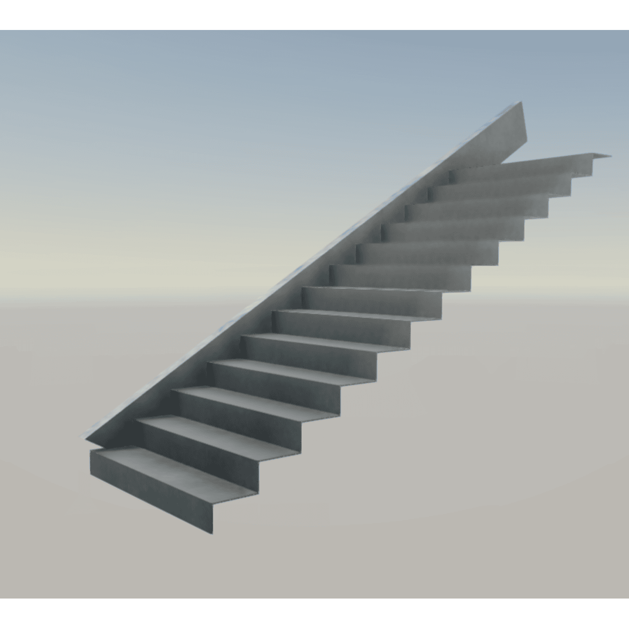
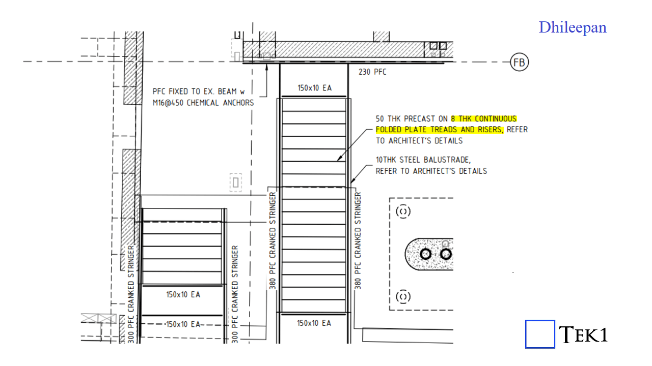
- Some items SHOULD NOT be quoted on a tonnage rate. For example: balustrades and stairs. Why? Because these items require a lot of work: they are intricate, and should not be quoted on a tonnage rate. Another example is grating. Therefore we must warn our client if there are special items, so that these may be priced separately.
The Actual MTO report:
- Please provide two MTO reports:
(a) Full Material List
- The first: is Koshy’s Material List.xls.rpt (Please use the file here saved here. (click on link)) – see instructions on where to save it below.
- If using line work from AutoCAD please use this link which allows for user defined attributes.
(b) The second: Excel – Material List – which shows all sub-totals.
(c) IFC file.
(d) db1 file
(e) and if applicable, your .dwg line work file.
- Where to save the .xls.rpt files? Ssave it to the appropriate file in your Tekla Program directory. In my computer it is here: C:\Users\All Users\Trimble\Tekla Structures\2023.0\Environments\Australasia\General\common_reports
You’ll have to go into the file and add/edit fields if applicable.
Please make sure that you do not double count “sub-totals” in the sub-total report otherwise you will get an incorrect tonnage report.
- Read the report: (i) is there anything with a zero weight?
If so, you have probably used the wrong “material” or grade. Is there anything obvious?
- I want the files format in .xlsx (if possible)
Why? Because when the client opens up .xls files they complain about some error. If you are using LibreDocs then please open your .xls file and save as .xlsx:
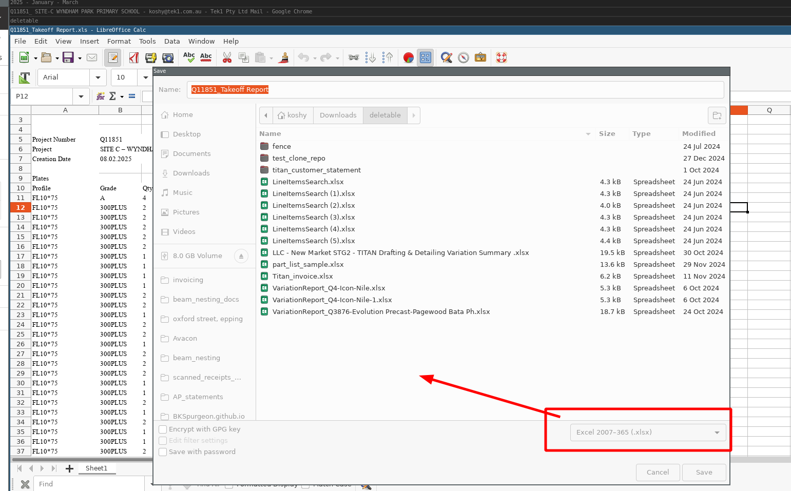
If you are using Excel, the please open Excel and save the file as .xlsx (one with and without.with an ‘x’ on the end of it).
Are you using Open Office or LibreOffice?
- We want Libreoffice – it is more recent and well maintained: please download and install it from here: https://www.libreoffice.org/download/download-libreoffice/
- Combine MTO and MC Reports in the same email
If I’m dealing with 10 projects then I have to coordinate 20 different emails. NO. I want them all together.
Separate Areas – Do Separate Reports
- e.g. You may have a main building, and a bike shed near the building – combine them into separate reports, so that fabricators can quote for them separately.
Provide Screenshots
- to make it easy for your clients.
Bridging Report
- I need separate bridging report.
- Include the bridging in the “overall” report.
On Refurbishment Jobs – make special notes
- These jobs are extra complicated, require a great deal of coordination (plus site measurements). Make special note of the difficulties inherent in such jobs:
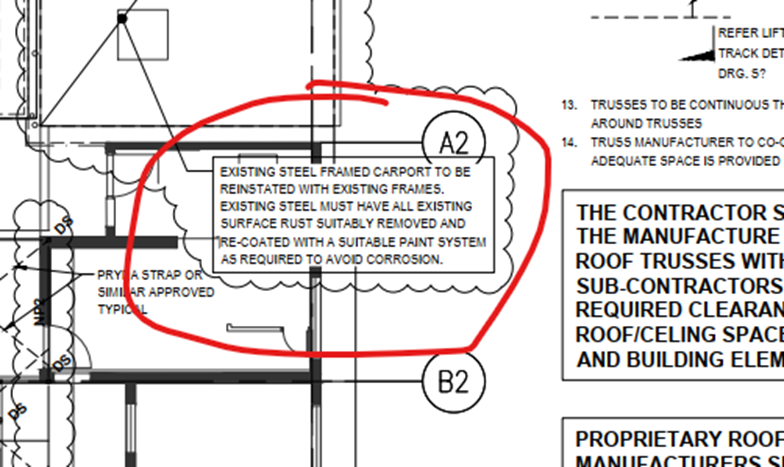
(This was for Respect Care Avonlea). Note: they want the EXISTING steel frames to have rust removed and recoated. Make such items clear for the person quoting – that this is to be in or out of scope.
Check architectural and sturctural drawings and note discrepancies
- Sometimes architecturals and structurals don’t match. They might miss steel e.g. frames.
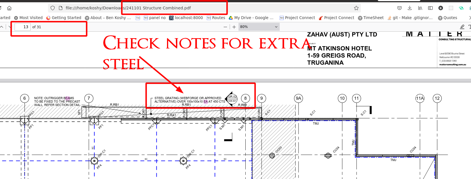
Check The Notes for Steel and / or other extra items items
e.g. see below – we need steel grating over EAs. Please make sure you don’t miss such notes.
- Not all steel is drawn with a line. Some steel is contained in a note. See example on Mt Atkinson structural drawings (page 13).
- When doing take-offs and marking pdfs – make sure to mark the pdf so that the reviewer can see that you have accounted for the steel in the markup.
Please quantify the exclusions in your report to give some basic idea on what the client needs to price. Please tell the client that your numbers are rough estimates and the client should verify independently – because we are not actually modelling those items.
2025-06-18 – Clients are quoting steel. Help the clients establish what is and is not in their scope. e.g. while you might EXCLUDE e.g. lintels in your modelling, you must provide a note saying to the client that LINTELS exist if they exist. This goes for ANY steel in the job. e.g. a special steel door, or grating – if they are excluded from your take off, you must still provide a note saying we haven’t modelled it, and if possible, to provide an estimation of it.
Add In Finish on Beams
MTO STEEL FINISHES – this is a part of take-off:
- Primer only
- Painted ( usually only for metal works ) we do not do Metal works mto
- Fire rated (Intumiscent or Vermicular)
These finishes must go on the member finishes
- Also when taking the snap shot, Each finish must have different color. There is already a method to render with steel finishes
- Different colors must be present on IFC files.
If in doubt – ask.
How to do bridging / purlin reports
Add Status For quote:
- Type in the quote number to get to the material_take_off page.
- Add in the ETA date.
Invoicing:
- When you finish a job – I need to create a “variation” with hours 0.
- In the “description” add in the following: (I) tonnage, and (ii) a google drive link to where your MTO reports are. This is for invoicing purposes – so the client can check our reports, and whether the details are correct.
- Mark it as “IFA” or ready to invoice.
Example of what to write on the “variation” on the MTO:
- 27.3 Tonnes
- Proof: Link-to-google-drive
Code via .dwg file
The source code + documentation is located here. (Sorry only accessible to Tek1).
We will be regularly updating the code, and documenting how we do material take offs.
List all files in the MTO:
- Go to the relevant folder in Windows File Explorer.
- Press the CTRL button on the key board AND then RIGHT CLICK h your mouse
- Click on “Open in terminal.”
- Then cut and paste the following command:
Get-ChildItem -Path . -Recurse | Out-File -FilePath .\file_list.txt
(Now the files should be listed in the “file_list.txt” file.)
Watch this video for further instructions:
Any MTOs submitted after 2025-07-15 which are non-compliant will risk incurring an immediate demerit.
Outdated Checklists and Special Notes Templates – Immediate Demerit to be applied
- Some are using outdated checklists / special notes templates – this prevents the latest process being applied uniformly across all take offs. This has happened before more than once. If this happens, and you’re caught, this will result in an immediate demerit, unless you can explain otherwise.
Folder Locations
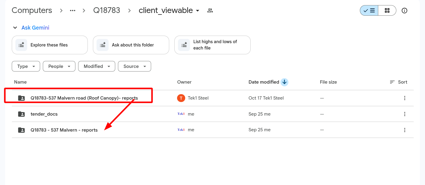
Please do not dump your reports in random locations. This makes it very difficult for clients to find especially if there are addendums, which means they MAY be using incorrect reports – which is unforgivable. If I catch you you will lose your entire bonus. (2025-10-31)
If there is no profile information – PICK a random profile! (2025-02-18)
Take for example the 537 Malvern Road MTO. Let us read from the special notes section:
Structural drawings indicate steel columns (SC1,SC2 & SC3) in structural plan, but there is no member profile nomination provided for these columns in the member schedule. Therefore, those steel columns were not included in this takeoff report. Please refer below snap showing yellow highlighted columns. In addition we have attached the highlighted markup for clarity
And then the following image is attached:
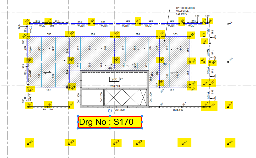
This is bad policy. Why? Because the client might not read the special notes and might mis-quote steel. it is better to add in an item with a nominated profile than to omit it entirely – in this case, at least the client will be ok if he quotes. If I see this happen again, you may endanger your bonus for a particular job.
Make items perfectly visible (2026-02-18)
This was for 26 Railway Parade, Hornsby. Almost all the items are not included, except the last one. But it is not highlighted in any particular way. Are you guys trying to confuse your clients? Highlight critical items to ensure it isn’t lost.
Here is another example:
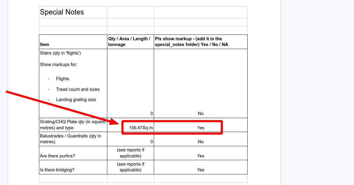
This is 156 square meters of checker plate – which is not cheap. If you leave it like this, the client might miss – so consider highlighting where relevant.
Isolated Material List Reports must have a separate IFC with them
(again on the 537 Malvern Road MTO).
When you have reports that segregate steel, you should also have the IFCs generated for each one of those reports. For example, if there is a PV platform, a canopy, a pergola, and roof steel, you should have separate IFC models for each one, as the case may be. This is so that people can recognise which steam corresponds to which items. Not doing so confuses myself, the client and wastes a lot of time.
Special Client
One of our clients wants their MTOs in a very special type of formatting. To that end, I have created an Apps script so we can transform our Tekla Members to be client with our client’s workflow:
We will also need to create a schedule of Member Marks which map to our client’s Steel Codes.
Backing Software:
- https://github.com/benkoshy/mto_uploads – Private repository to transparently manage drawings and versioning via Google Drive API and Google workspace
- Google App Scripts – to manage mapping from Tekla to our client specific take off codes. Link and instructions will be posted here.
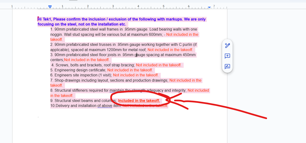
Answers to RFIs need to be proven with markups
e.g. see Q18810 – PEGS Junior Boys Campus Stage 1 by Hari.
This is the question by the client / builder:
Include:
- Window Shround Secondary Steel
- Refer elevations BE3 through to BE5 on ST-300-02
- Structural Steel Member shown in blue on Concrete Outline Plans
- These are shown on structural documentation throughout
- Structural Steel Lintels
- These are shown on structural documentation throughout
- Structural Steel to Makers Façade
- Refer elevations BE3 through to BE5 on ST-300-02
- Structural Steel to GRC Metal Cladding
- Refer elevations BE3 through to BE5 on ST-300-02
- Secondary Steel to Makers Entrance Eaves Gutter
- This is shown on ST101-1
- Structural Steel Framing concealed within ceiling cavity
And here is the response:
Inclusion:
- Window Shroud Secondary Steel.
- Structural steel lintels.
- Structural steel to makers facade.
- Structural steel to GRC metal cladding.
- Secondary steel to makers entrance eaves gutter.
- Structural steel framing concealed within ceiling cavity.
- Structural steel framing of planter storage(WT-03).
Exclusion:
- Steel angle for perforated balustrade including steel plate and steel verticals
- Steel plate to support door frame
- Terrible. Why? (a) Poor English: First of all the grammar is not clear. What do you mean: “Inclusion”? Does this mean you have included the steel or not? (b) Why Excluded? Secondly the exclusions: any reason why this is excluded? The client is paying you for doing the work, so you need a very good reason to exclude it, or there must be a measure, or a proxy by which you should enable the client to quote. (c) No proof: Generally speaking, if someone asks you a question, it is not enough to give the answer. You must provide your reasons / proof as well. In this case, if a client asks if you have accounted for PF1 profiles, what will constitute is the isometric view with the mark numbers. That is enough.
Organise Folders – Don’t be a slob
Architectural Finishes
Please say yes / no if arch finishes are required. IF clients progress in the tendering stages, then they will almost certainly request an architectural review of the paint finishes. This might be an additional $6000 / tonne extra cost.
How to fill out a checklist
WARNING: How to fill a checklist. If people are filling the checklist first, and then doing the work later – if you forget or miss, that is a huge cost to me. You will incur punitive demerits from now on (i.e. not only will I remove this MTO bonus, but I might take away 2-3 more). Please take care.
Paint Finishes
For certain projects, it is necessary to give a thorough audit of the architectural finishes. Once you have done that, you need to communicate all the results to our clients via an Excel Spreadsheet. Secondly, reviewing the architectural finishes take time / complexity. Therefore, we need to submit a fee proposal to our client before do the work. In addition, we need approvals.
Here is a sample file: Paint Finishes Sample here
Cell References
If functions
Search Function
iferror function
Transpose Function
How to put all of the above together
=IF( IFERROR(SEARCH( L$5, $E6 ), 0), $K6, 0)
You must use AREA instead of tonnage for the Paint calculations. The video above uses the wrong column, but you need to change it so that it uses square metres.
- Where: L$5 is the paint finish (the search term input)
- Where $E6 is the finish column (aggregated)
- Where $K6 – is the tonnage you want to capture.
- Please make sure that you don’t have two finishes which are encompass each other. e.g. with “PT1″ and PT11” the PT1 can be found and captured within a PT11! So your results will be incorrect.
Renaming Files
Clients find it annoying to open Excel if the file names are the same. Make it easy for your client my renaming the files so they are unique across the entire project where you have many different report sets – e.g. Building A, Building B etc.
Downlaod Power Toys from here: https://github.com/microsoft/powertoys
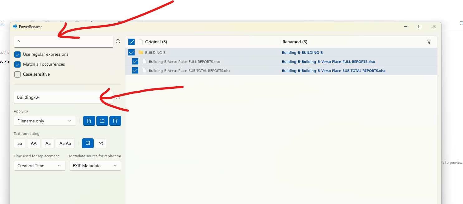
Please find above the settings required to rename a file.
Executive Summary
If your reports has many sections and sub-sections, you need to provide an “EXECUTIVE SUMMARY” to make it easy for your client to collate the tonnages and to quote the job. Make sure you add it to the “OVERALL TONNAGE” file.
Building A: x tonnes
Building B: y tonnes
Building C: z tonnes etc.