In this blog, we will look at how to create and share new materials in a Tekla model. By default, Tekla comes with a predefined list of materials stored in the system drive (C drive). However, in many projects, we often need to add custom materials based on project requirements. To add a new material, go to the Menu at the top left corner, navigate to Catalogs, and then open the Material Catalog. From there, select an existing material, right click & selct “Add Grade,” rename it as required, and assign the appropriate density. Once saved, the new material will be available in the model.
When sharing the model, especially using the db1 file to reduce file size, the newly added materials may not be available to the recipient. This is because custom materials are stored separately. To ensure the other user can access the same materials, you need to share the file named “matdb.bin” from the model folder. This file is created only when new materials are added and must be included along with the db1 file.
Alternatively, there is another method to share materials. In the Material Catalog, you can use the “Export” option available at the bottom to save the material data as a separate file. This file can then be shared, and the recipient can import it into their Material Catalog to access the same materials.
Watch the video below for a step-by-step demonstration of this process.
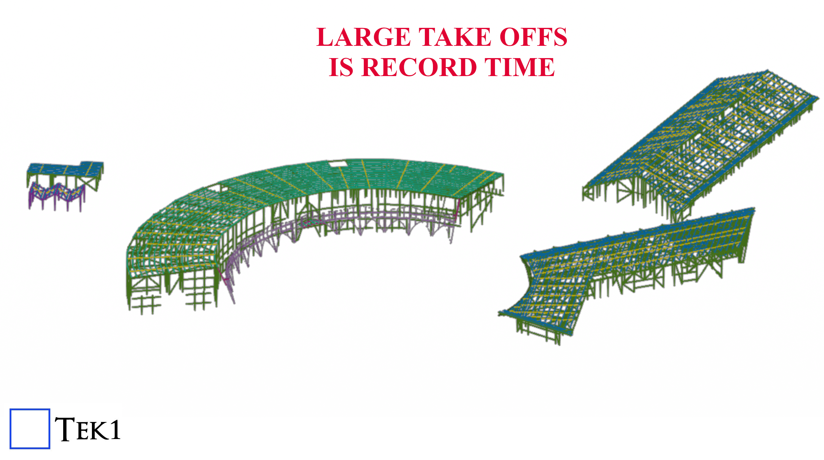
Load bearing precast element is anything that receives load from a precast or structural members and transfers the load to another structural member or precast. These precast elements can also be used along as façade, boundary walls, or for architectural design purposes.
What is non-load bearing precast element?
Non-load bearing precast element is anything that may receive load but must not transfer loads to any other structural members or precast. Normally these kind of walls are used only for partition, façade, boundary walls, or for architectural design purposes
What is Partially-load bearing precast element?
Partially-load bearing precast element is anything that receives load from a precast or structural members and transfers the load to another structural member or precast. But only a portion of precast receives and transfers load and the remaining portions will act as non-load bearing ones. (Single precast element which acts both as load bearing & non-load bearing)
Data’s, panel types & other details for
Load-bearing element
Non-bearing element
Partially-load bearing element
Grade, can be higher upto 80MPa
Grade enough be 40MPa (UNO)
Grade, can be higher up to 80MPa
Gap between two elements are filled with grouting material of required grade
Gap between two elements are filled with Soft joint caulking only. no grouting.
Gap between two elements are filled with grouting material of required grade, extent of filling is for load bearing portion. Remaining portion will be soft joint caulking only
Dowels to be black finish (UNO)
Dowels to be Galvanized finish
Dowels to be Black or Galvanized finish, as per load bearing extend (UNO)
Dowel length, size & spacing as per Engineer’s requirement
Dowel length, size & spacing as minimum as possible after discussing with Manufacturer or Engineer
Dowel length, size & spacing as per Engineer’s requirement for LBP portion Dowel length, size & spacing as minimum as possible for NLBP portion
Dowel & Grouting materials will transfer load to adjoining element
Dowel will be used to position the precast element & no grouting material present to transfer load. So loads will not be transferred.
Combination of LB & NLB criteria
No ring seal around the dowel
High density foam ring seal around the dowel
No ring seal around the black dowel High density foam ring seal around the Galvanized dowel
Grouting material will cover the dowel, so oxidation in dowel is negligible
No Grouting material, oxidation in dowel is possible. So high density foam ring seal is used and dowels are galvanized to prevent oxidation in dowel
Combination of LB & NLB criteria
No additional tubes or caps needed
Plastic tube will be placed over upper half of dowel. Compressible cap will be placed over the top of the dowel bar.
Combination of LB & NLB criteria
Connection with slab must
Connection with slab may not needed with respect to engineer requirement
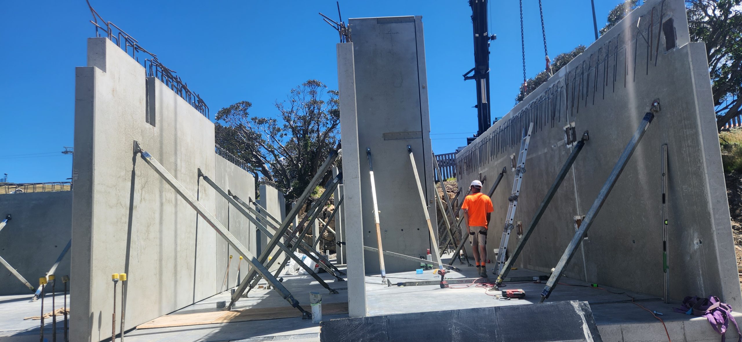
This is an image showing how precast panels are propped
Propping parameters
Usually propped at 2/3rd height.
No of props usually 2
if the panels are wide could go to more than 2. But rarely 4.
For Panels which span 2 floors, There could be 4 props. 2 below the floor above and 2 above. When you have such a case you have to show opening on the slab through which the upper props will pass.
How long will the props stay in place.
Usually between 1 to 2 months. It could be longer if the construction pace is slow.
How many props are usually used in a multi storied construction?
Depends on construction speed number of panels.
But the number could be around 200.
With prop hire rate of around $3 per week, you can see that the cost of propping is not very small. When you are estimating for precast, it may be good to consider how many props will be used and what would the cost of propping for a project
Propping is highly skilled job. Improper prop installation can cause accidents shutting down sites, sending stake holders broke. Not to speak of the harm it does to the site personnel.
Who designs the prop.
Most of the the time props are drafted by the detailer and submitted for approval to the engineer.
Detailer cannot issue panel or propping drawings unless there is an approval from the engineer. The certification from the engineer is a must. Without that shop drawings cannot go for construciton.
Without certification, the propping is no go good, illegal and not fit for purpose.
Insurance companies will not cover if there any issue because of prop failure if the drawings were not certified by a qualified engineer.
must be installed and enabledWrong $CFG->dbtype. You need to change it in your config.php file from ‘mysqli’ to ‘mariadb’
site not https
if this test fails, it indicates a potential problemIt has been detected that your site is not secured using HTTPS. It is strongly recommended to migrate your site to HTTPS for increased security and improved integration with other systems.
Steps Edit Bolt Catalogue. Add the Ferrule bolt in this case we are going start from BOLTFB1640 and create BOLTFB1655 Then we add a bolt Assembly catalog. Again we start from Bolt BOLTFB1640 and create BOLTFB1655 Then we use that in tekla to model the bolt. When you model the bolt make sure 1. No nut is used 2. Washer is on the head side. 3. Cut length is negative of the length you want. This decides the length of the bolt in report. Most important do not ignore — Take report and check.