In this blog, we share a proposal we made to the builder to make installation easier on-site.
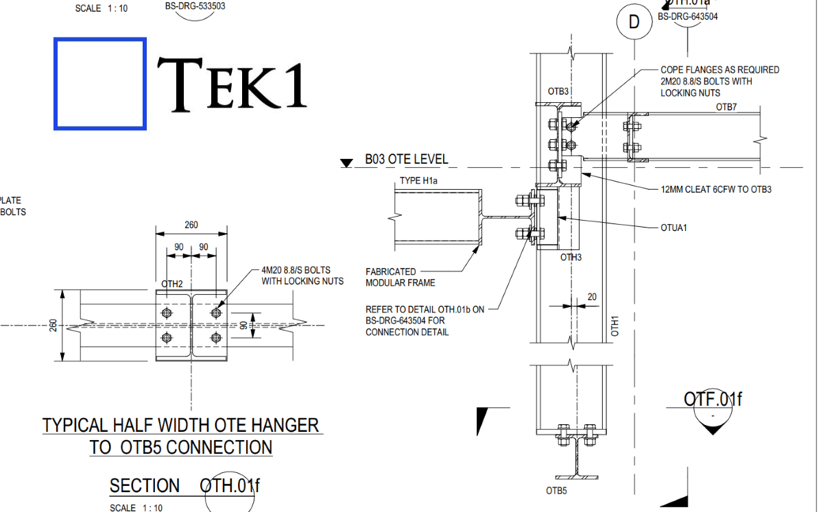
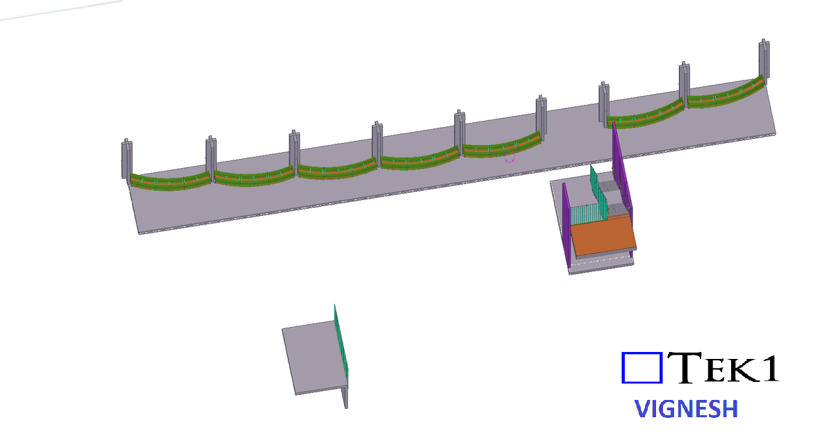
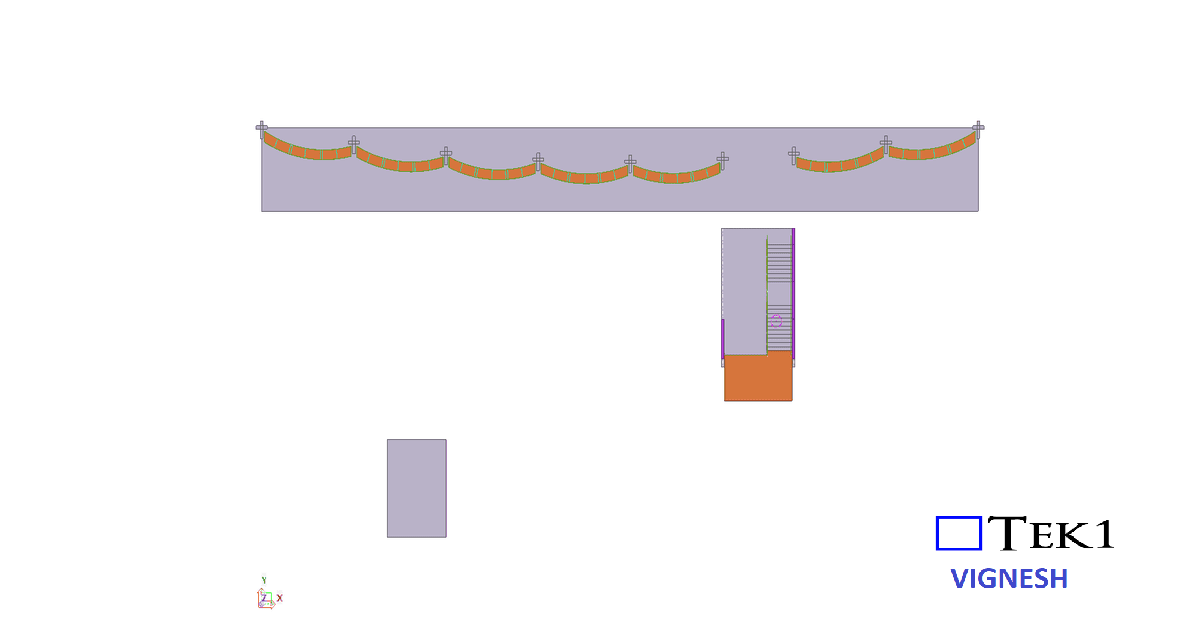
In the OTE platform steel, we provided a PSD beam (OTB5) to support the platform screen doors below. These beams will later need to coordinate with the door manufacturer’s system.
However, in practice, structural steel is rarely placed in the exact designed level due to factors like concrete alignment, mill tolerances, and site conditions. If the beam is installed as per the design without adjustment options, it may not match the required level for the doors.
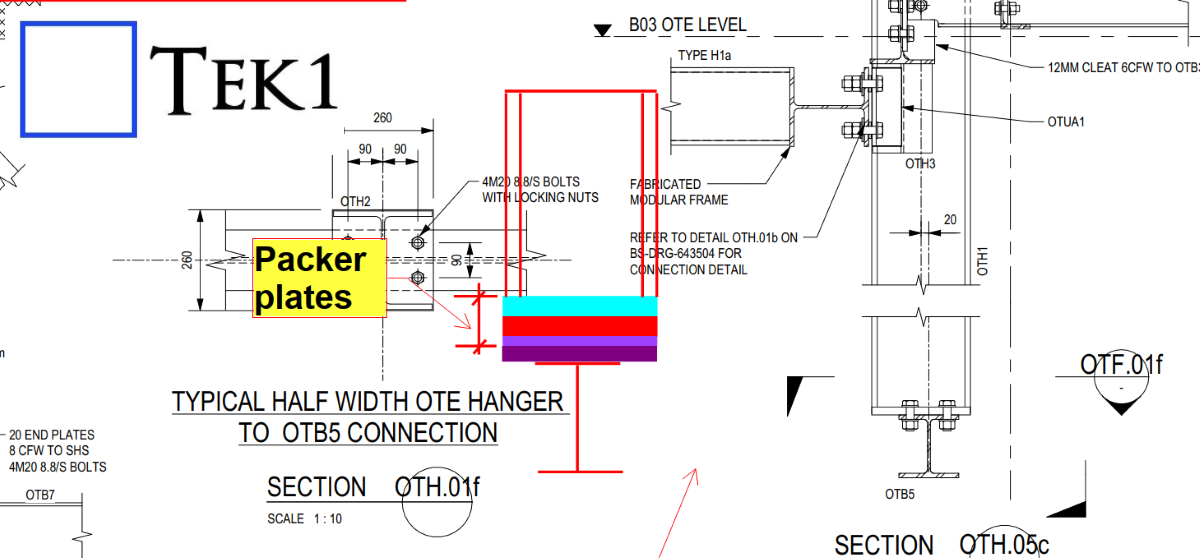
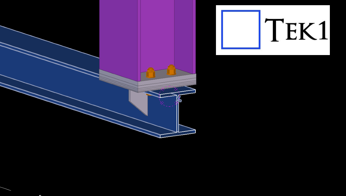
To solve this, we proposed adding packer plates so the PSD beam level can be adjusted during installation.
The client accepted our proposal, and this solution will make the erection and alignment process much easier on site.
Cloning of Assembly Drawings in Tekla is the Smartest Way to Improve Detailing Efficiency
In structural steel detailing, efficiency and accuracy are critical to delivering projects on time. As projects grow larger and more complex, detailers must find smarter ways to manage repetitive components and maintain consistency across drawings. One powerful feature that helps achieve this in Tekla Structures is Assembly Drawing Cloning.
Cloning assembly drawings is a highly effective method that allows detailers to duplicate an existing assembly drawing and apply it to similar assemblies within the model. Instead of creating drawings from scratch every time, detailers can reuse a well-configured drawing layout, saving significant time while maintaining uniform standards across the project.
In steel structures, many assemblies such as beams, columns, bracing members, and connection components often share similar configurations. When these assemblies are modeled with comparable geometry and detailing requirements, cloning becomes an invaluable tool. By copying an existing drawing and adapting it automatically to another assembly, Tekla helps detailers maintain consistency in dimensions, views, marks, and annotations.
Another advantage of cloning is its ability to intelligently adapt to small variations between assemblies. Tekla automatically adjusts views, dimensions, and annotations to match the geometry of the new assembly. This allows detailers to reuse drawings even when there are minor differences in member length, hole positions, or connection details
Please refer to the video below, which elaborates on the cloning process and the working method in Tekla Structures
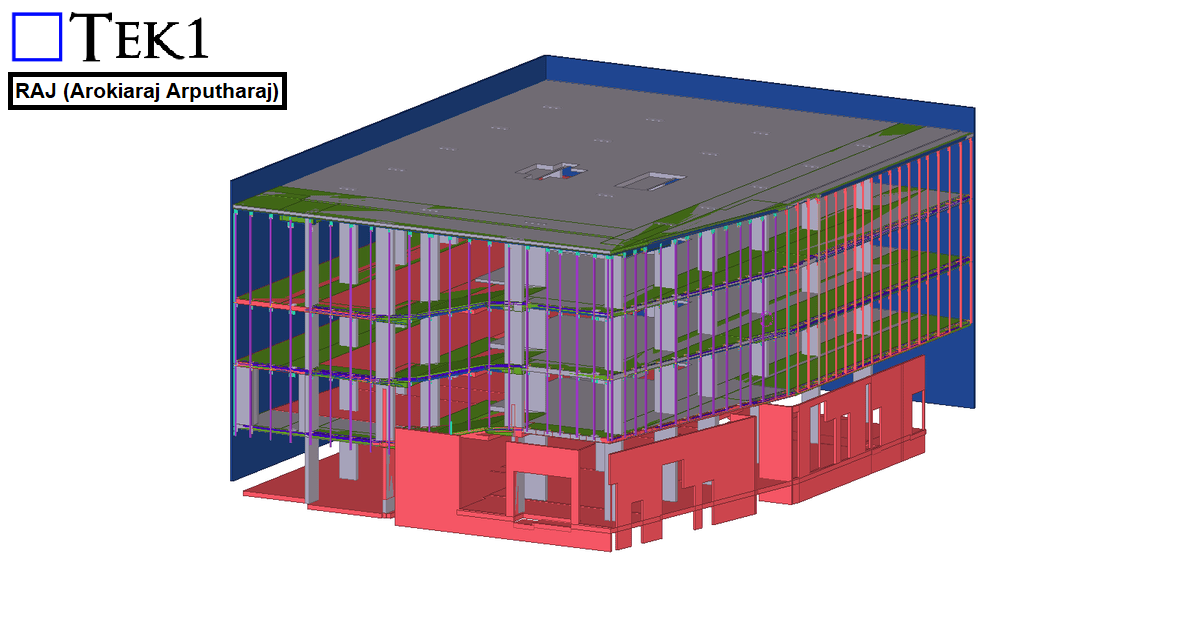
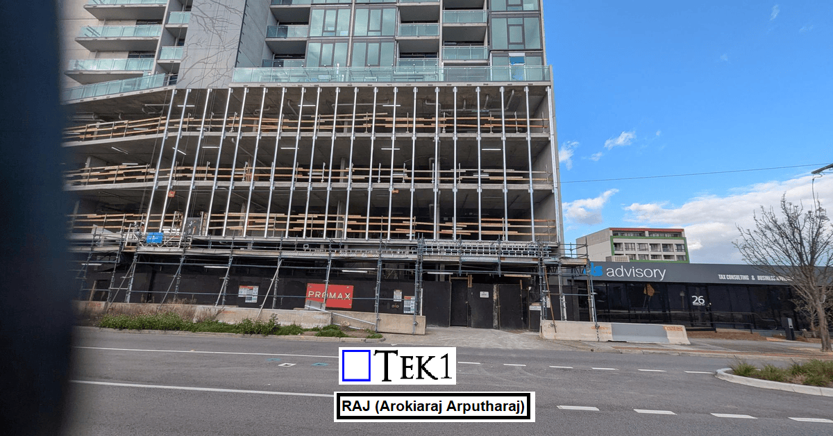
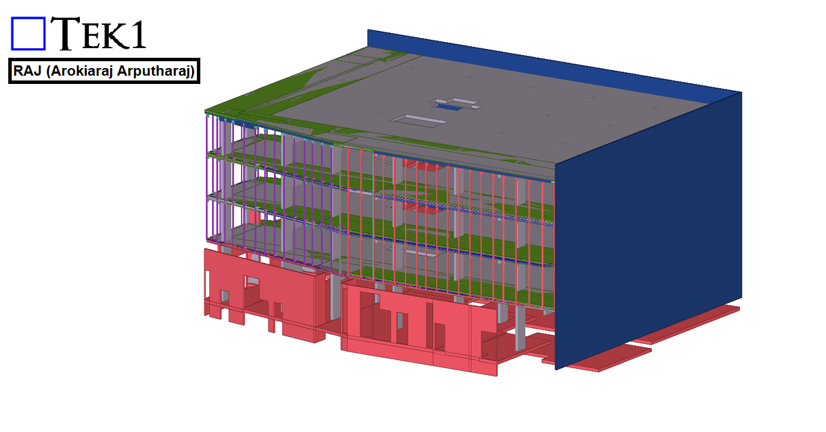
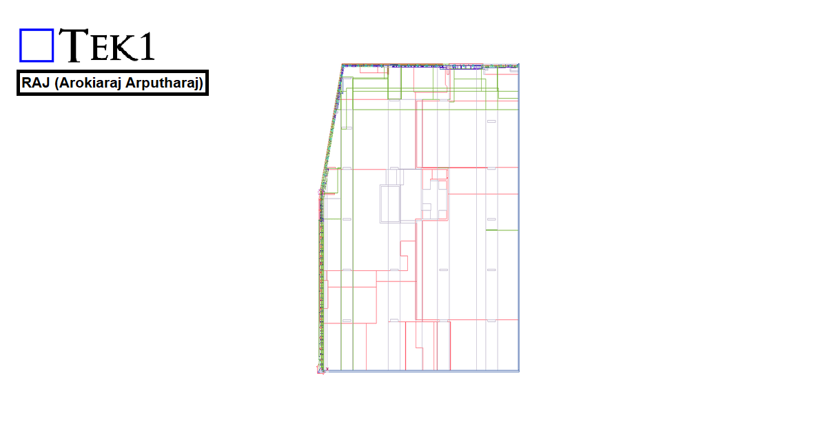
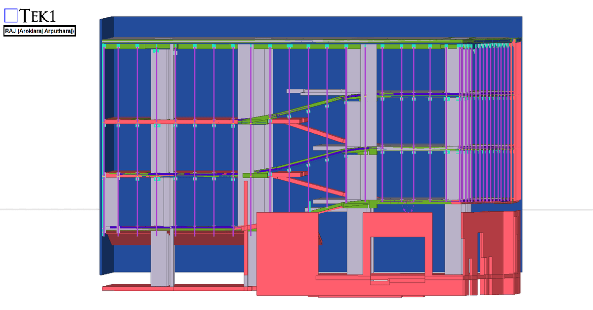
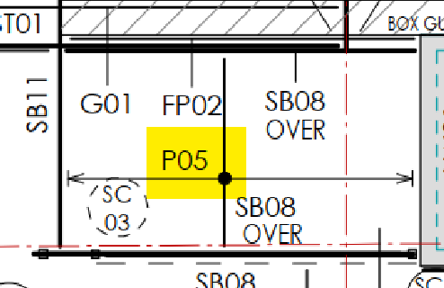
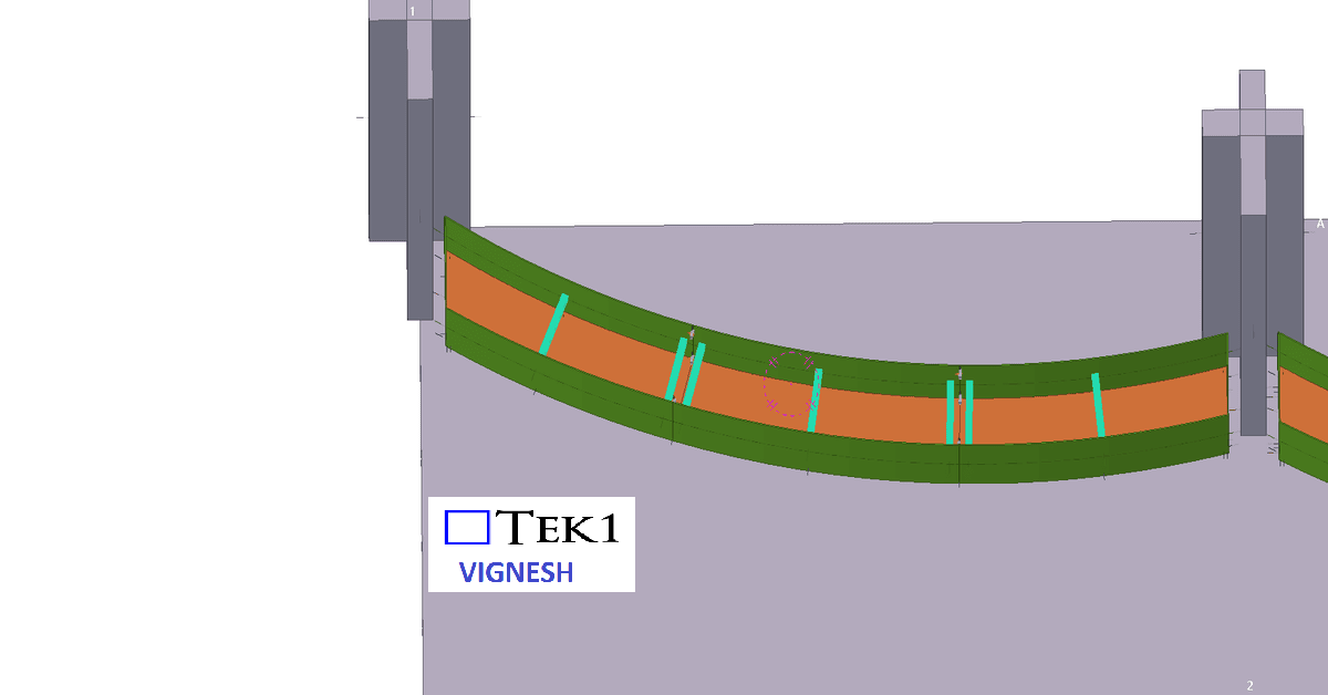
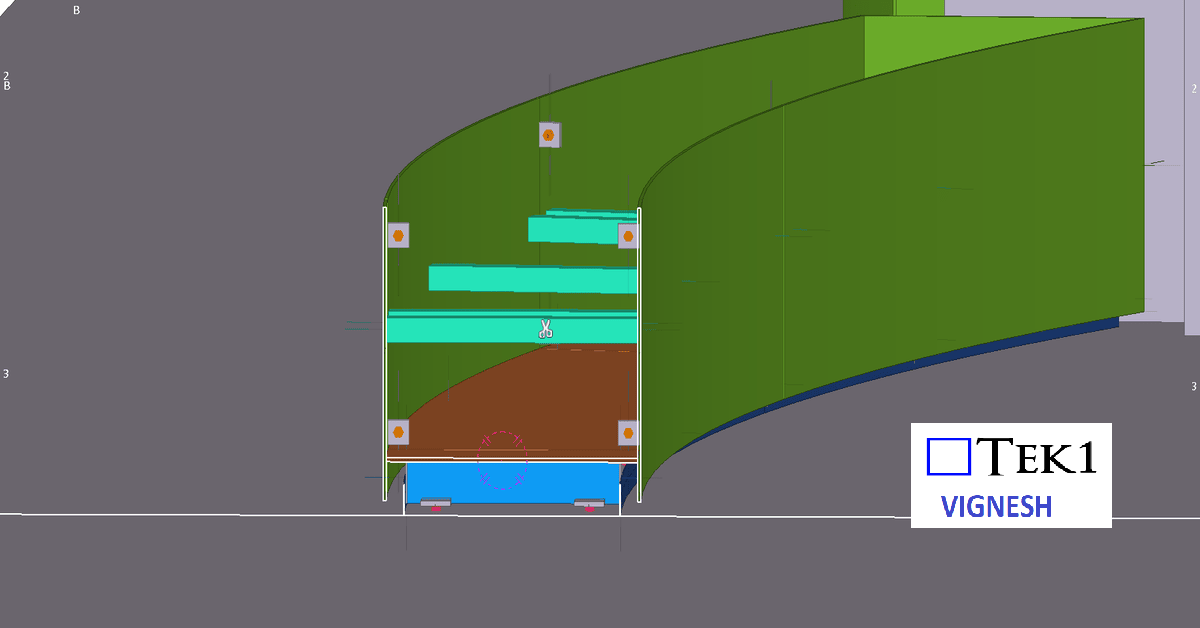
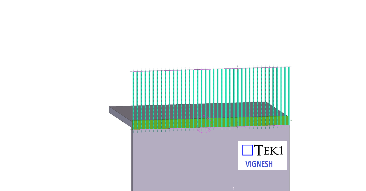
For the 27 Scott Street project, the client requested that the façade posts be installed with sufficient clearance so that the fixing anchors do not clash with the PT cable lines.
We carefully followed the client’s requirements and coordinated the design to ensure that the anchors clear the PT cable lines. The steel was successfully erected without any issues.
We would like to thank the client for giving us the opportunity to be part of this project.
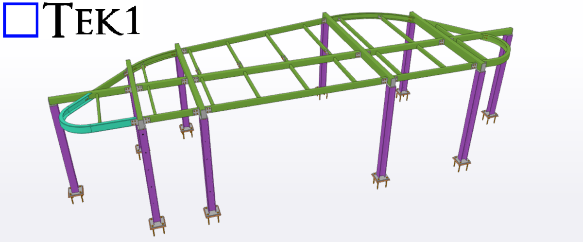
In Australian steel detailing, understanding roof and purlin specifications is essential for delivering precise and efficient designs. In this blog, I’ll share an experience highlighting the significance of addressing roof slope issues during detailing.
The Issue
In a structural drawing, the purlins were shown running north-south, which suggested that the roof slope would be east-west (since purlins are always perpendicular to the roof slope). However, when we reviewed the architectural drawings, the roof slope was indicated as running north-south—a direct contradiction.
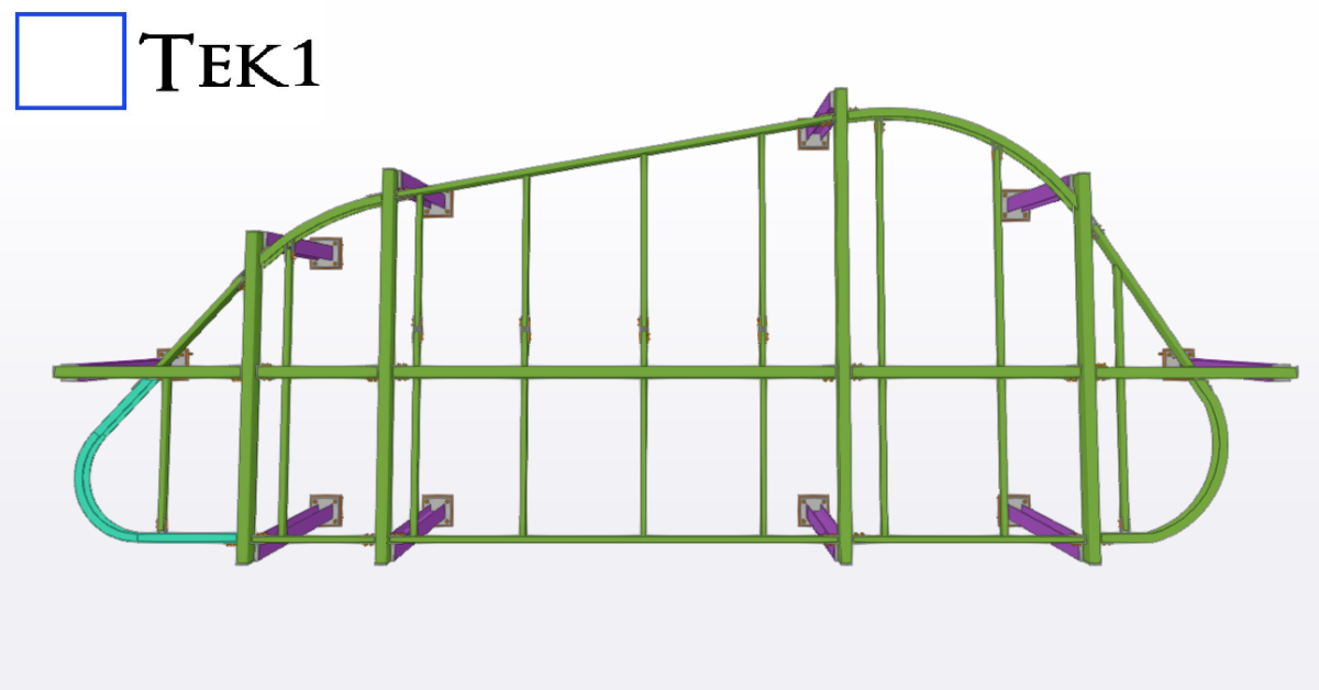
The Resolution
We raised the issue with the client, who confirmed that the architectural drawings superseded the structural ones. Following this clarification, updated drawings were issued, with the roof slope correctly aligned in the east-west direction.
Key Takeaways
Cross-Check Drawings: Always verify alignment between structural and architectural drawings, especially for critical elements like roof slopes.
Communicate Early: Raising discrepancies early saves time and prevents costly rework.
Stay Updated: Ensure you work with the most recent drawings to avoid confusion.
Roof and purlin alignment might seem straightforward, but even small errors can have significant implications. Attention to detail and proactive communication are key to successful detailing.
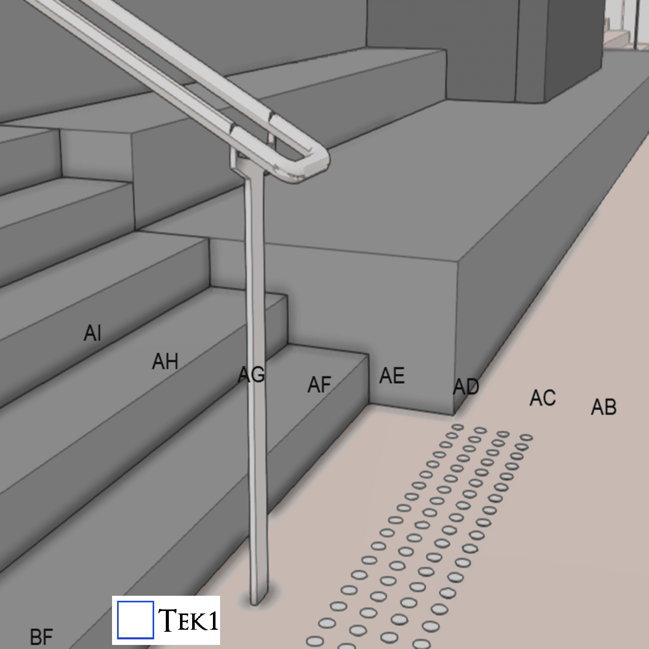
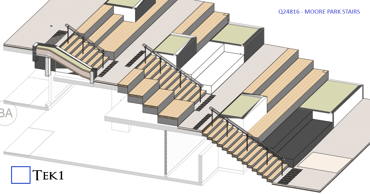
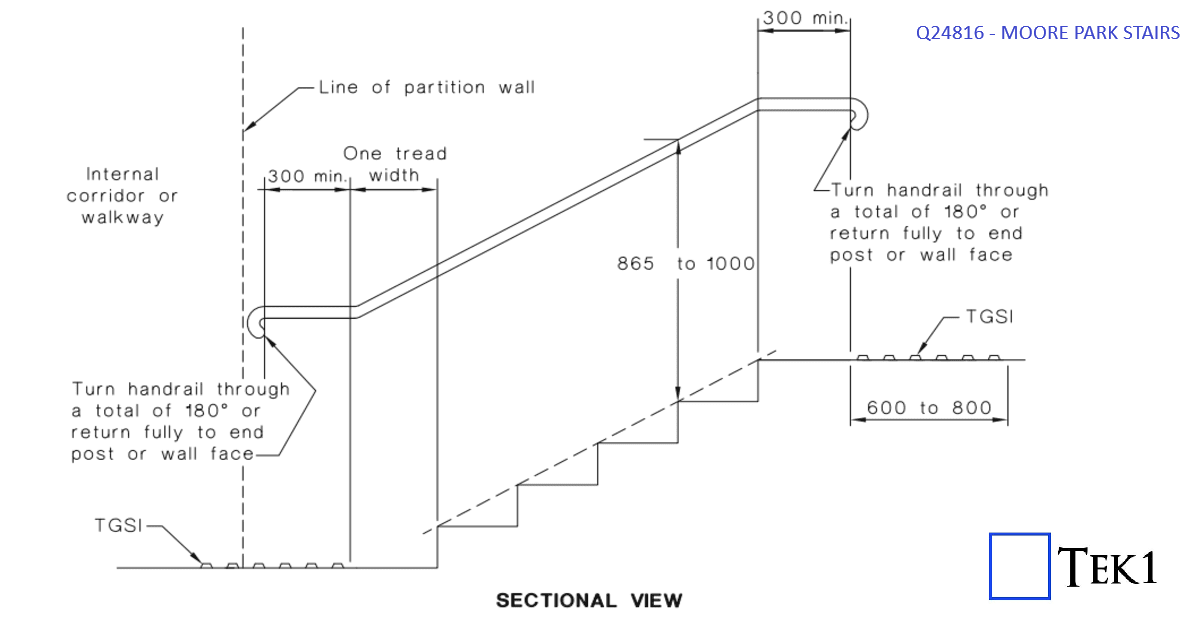
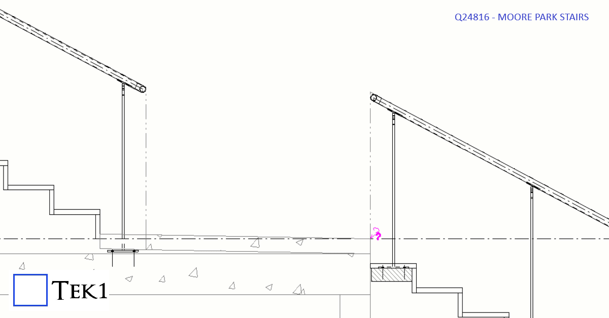
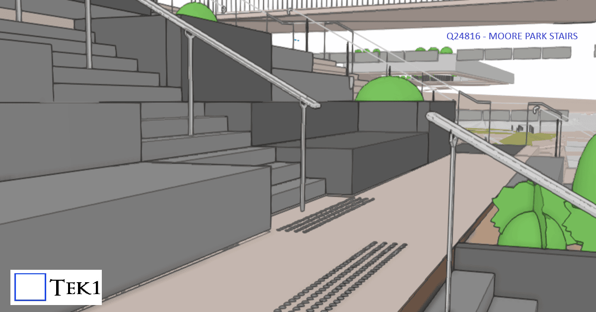
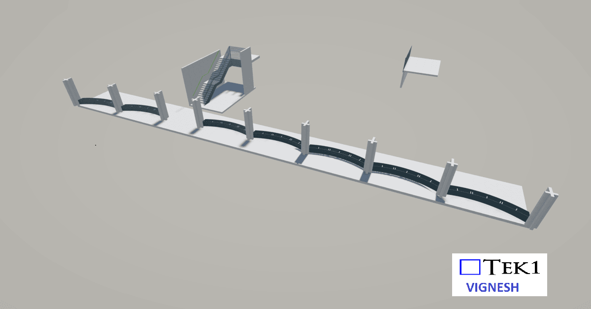
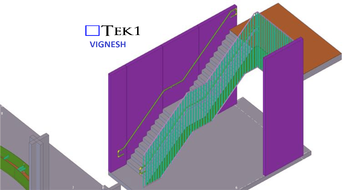
At Moore park, there are several stairs & ramps. Among them is a stair which connects walkways at different levels. The direction of the stairs is perpendicular to the direction of the walkways.
According to the sandards, handrails at stairs must extend beyond the stair flight to improve accessibility and safety. The standard requires:
300 mm extension beyond the landing nosing at the top, and
The going of the first tread + 300 mm extension at the bottom.
However, extending the handrail rail would protrude in the walkway & could cause collision hazard or reduce the effective width of the walkway.
To avoid this, the handrail extension was omitted. The architect has marked this as performance solution & this is one of the few cases where this 300mm extension does not apply.
We are proud to be a part of the team in Marymede Planter box project.
Our detailing team worked closely with architects to ensure tolerances and offsets were met without compromising design intent With a limited fabrication and erection window, our detailing team adopted a fast-track workflow using Tekla Structures for 3D modeling.
This allowed us to provide early shop drawings for procurement and parallel review of sections still under coordination.