A very handy method. Often detailers will ask for something to be placed on a particular layer. But since they are using a 100 different drawing templates without any consistency nor standards, the onus is on you to impose that standard on them. So you’d have to check for a layer and add it if it doesn’t already exist. Anyways, that’s enough griping: here is the code:
Author: admin
-
Time Waits for Nobody: Steward your resources effectively

Efficiently steward your resources: namely time. Massive Investment With Little Return?
There are a million things out there in the world. Are you going to learn/master it all? Here’s how the typical educational program works – a monumental waste of resources in my opinion:
- 12 years in basic secondary and higher ‘education’.
- Another 3-6 years in tetiary ‘education’.
- Learning a billion other frameworks
And all the while, you are “learning” things without combining it with any real practical applications whatsoever. In fact, the application of your learning is some contrived hypothetical problem in an exam. That’s a waste. If you’re going to learn, then you should learn while also producing something useful to mankind: there’s no sense in wasting 3 years on a PhD which has no practical purpose apart from giving you the right to call yourself a PhD. (Don’t get me wrong, tertiary education does have some awesome benefits too).
In programming, in the same way:
- Are you going to master HTML, then
- CSS
- Javascript
- React
- The HTTP specs
- TPC/IP
- Data structures and algorithms (Knuth’s four volumes).
- As well as useful tidbits of info like Martin Fowler’s Refactor, or Uncle Bob’s books,
- As well as Ruby, and the rails framework,
- Databases and SQL
- Git
- Ioc containers
- Then Windows desktop programming: Tekla API and AutoCAD .net plugins + Unit testing and mocking frameworks.
…..before you then start programming your world-changing application?
The key is to learn as little as possible. And when I mean little, I mean as little as possible. One day for learning some basics, before starting to write your first rails app etc.
You’ll definitely struggle.
But provided you can quickly resolve those issues, you will have done A LOT without spending too much down time ‘learning’ a lot of useless crap. You’ll win out on time.
Get something half working, and if it has promise, then you can invest further resources into perfecting it. By the time you learn something, you may find that it is obsolete.
Avoid Massive Capital Expenditures If Possible: Get An Expert To Do The Work
Even better is to entirely avoid learning the implementation but to focus on learning and understanding the principles of what/why something is working as it is working and to simply outsource the implementation of those details to an expert. A fixed price for time. The hard part is finding that expert. That connotes you being able to distinguish between professed experts and those who aren’t – and that in turn requires knowledge of high-level functions. But if you don’t even know the higher level functions of what is going on, and if you don’t know how to procure an expert, then you’re effectively no better than a highly trained chimpanzee.
In other words, the common problem in programming (as well as in business) is to find a way to obtain maximum output with the least amount of expended resources (both current and future).
The basic point being: Everything takes time. Make it work with the least amount of time and resources expended.
Summary
- Time and resources are limited.
- Do the most you can with the least you have.
- If something shows promise, then add some fuel to the fire and let it shine!
-
First rule of Building and Construction: Make sure it can be built!

Stay out of danger! “A prudent person foresees danger and takes precautions. The simpleton goes blindly on and suffers the consequences.”
So it is the case also in building and construction.
Here is a primer of how and why and where things go wrong – if they do go wrong. As with most things, problems start in the administration and design of projects. From there, they snow-ball.
To summarise:
- Stay away from problematic jobs: they will cost you money, and worse, time. You can tell whether it’s gonna be trouble just by looking at the architect’s designs, and by knowing who the builder / project managers are.
Architects
- What does the architect do? The architect comes up with a design. The architect is primarily interested in making a building look good. They also want the building to have extreme versatility – for it to be uber convenient; eco-friendly – for it to have the ability to recycle human refuse into heat and light and potable drinking water etc. etc;
- What are the interests of the architect?
- They want to make a name for themselves. So they come up with all sorts of designs which might make you wonder whether they were smoking weed or crack cocaine? It will not do for an architect to make an ordinary building, with a straight edge: no, no, no! He must make the building flutter and shimmer in the wind. She must otherwise design it with an ocean liner on top of it; or she must make it resemble a half-folded “deck of cards” etc. etc.
- Architects’ interest are not the same as others’: Generally the problem with the architects are that they invariably design buildings which are contrary to the interests of the other stake holders in the game: it might not be feasible to build such a building given: (i) time, (ii) structural integrity, (iii) and/or costs. E.g. the Marina Bay Sands and the Burj Khalifa were phenomenally expensive. The architect is not incentivised to worry so much about cost/time. The great Gaudi, on the subject of the extremely long construction period of the Sagrada Familia, is said to have remarked: “My client is not in a hurry.” He can say that because he isn’t paying the bills.
Engineers
- What does the engineer do? The engineer’s job – a difficult one – is to make sense of the architect’s design and to ensure that the building does not fall down.
- What is the interest of the engineer? He is primarily concerned with ensuring that nobody dies, and that the building is structurally sound, and that somebody doesn’t sue him 5 years later because the building imploded.
Shop Drawer
What does the shop drawer do?
- It is the shop drawer who has to make sense of the above madness and to make sure the structure can actually be built (and sometimes designs up for tender simply cannot be feasibly built).
The Consequences of Bad Designs
Here are the consequences:
- Extra Costs:
- Reworking flawed designs on site. Rectifying on site is probably x5-10 times more expensive than getting it done right in the workshop. Who pays? Not the designer.
- Reworking designs – in the office before fabrication. It’s cheaper than on site, but you’ll spend a lot of time here. See the explanation below for more detail.
- The builder will be squeezed of cash. It may mean that you (and other trades) might not get paid on time, if at all.
- Time Lost:
- If you get a bad design, that means it is your job to spend time communicating those changes to the architect and/or the engineers. There can be hundreds and sometimes thousands of emails flying back and forth on the job. Now you have to worry about leaving a document trail behind. Are you being compensated for this?
- Architects will usually have to issue revisions to their designs as their cock ups come to light. Other trades may be affected? Which ones? Who knows and who cares! Blast those revisions out to everyone on the job. So rather than specifically target the communication re: those revisions to affected people only, they email blast out those revisions to everyone on the job – from the MEP folks to the birds sitting on a near by tree. Everyone is notified. That means all of those trades have to spend their time scrutinizing those changes to make sure that it does not affect them. And if those changes force further changes, then the entire cycle repeats itself. The cost blow out is exponential. One or two changes every now and then is ok, but when you are looking at about 15 drawings, amongst 100s of changes a week, that becomes extremely tedious, time consuming and onerous.
- If a design doesn’t conform to AS standards who pays? Not the architect – who’s job it is to design it properly in the first place. No, you can pay for that instead. Don’t pay for someone else’s mistakes: stay away from bad designs and problematic jobs.
-
Should you cast in a Reckli Groove in a precast concrete panel?
There are situations where you may prefer to cast in a Reckli groove.
If the Reckli is contained within one panel, then you must surely cast it in. However, if the flashing groove runs past several panels, it may be better to saw cut the groove at site.
-
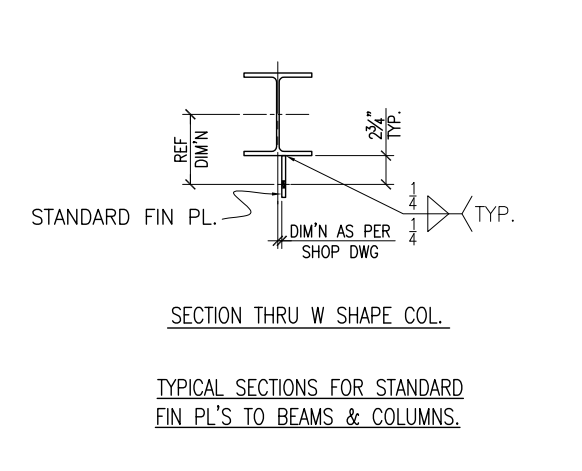
Detailing cleats to connect to beams
Detailing cleats to connect to beams.
The main principle is the work points of the beam to the column must intersect. To achieve this the cleat should be offset to onside by half the Beam web thickness. This is usually done when you layout the main members. Make sure the layout is good
Here is a drawing to a shop detail which shows offsetting of the cleat to beam or column center line. Please note that the beam centerline and column center line should be matching. For US Fin plate the bolt distance is 2-3/4″ from the face of Beam/Column. For Australian situation, it will 55mm
-
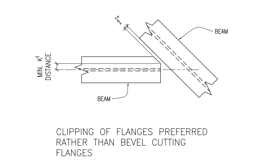
Bevel Cutting Beam End for Fabrication
How to Detail bevel cut Beam Ends for Fabrication
Given here is an image of how do the bevel cut in a beam to beam shear plate connection where the beam does not connect perpendicular. There is no benefit in creating full width bevel cut since it will only add material. All you have to do is remove the clashing bit
-
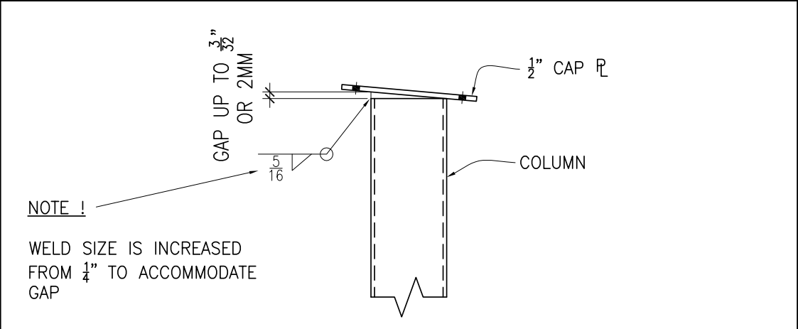
Skew Cutting Col end to match Inclined End Plate
How to detail Column end when end plates are skewed
Here is a picture of an included end plate. Fabricators and easily weld and fill up upto 2mm. Hence there is no need to skew cut end plate. Will save a heap of time and cost in the fabrication shop.
-
Ignore White Lines in Selection Filter (AutoCAD .net API)

We want to select line times of a certain color. We want a selection filter which simply ignores certain types of colors.
Here is the ‘simple’ result I came up with:
.jpg)