It quickly and easily allows you to create elevation drawings given a certain marking plan view of a panel. You need to first: (i) select the applicable panel lines, then (ii) you need to select a view direction. The way you select a view direction is by selecting a panel line which is perpendicular to the view direction, and using the resulting jig to select the direction you want to view the panel. (iii) Then, you must use a bounding box to select any applicable grid lines you need. (iv) use the resulting jig to position the panel lines where you want.
When you are dealing with 100s, and perhaps even up to a 1000 panels per building, this can become extremely cumbersome and time consuming. Why not automate the entire process? This allows you to do things faster, to get the drawings out faster, and (hopefully) to build the panels faster, and ultimately the building faster. Speed is absolutely paramount! The faster a builder can get on and off of a construction site, the faster they can get paid. This lowers their working capital needs, and accordingly, their financing costs (however that may arise). Speed is king!
Considerations When Transporting Panels to Site
Every truck has a:
Size limitation (both length and height), as well as a:
Weight limitation (there is a maximum capacity).
Secondly, trucks have different limitations, depending on where they are transporting a panel. E.g.
Trucks passing through the CBD (central business district) have different: length/height and mass requirements compared to those that are not, furthermore, these requirements are different depending on whether the truck has a permit or not.
Let’s suppose you have the following hypothetical situation – take out a sheet of paper and pen and try and solve this by hand:
Truck A
Length limitation: 6 m
Height limitation: 3 m (but a height limit of 2.5 m in the CBD; and a height limit of 3.2 m with a permit)
Weight Limit: 12 tonnes.
Truck B
Length limitation: 4 m
Height limitation: 4 m (but a height limit of 2.5 m in the CBD; and a height limit of 3.2 m with a permit)
Weight Limit: 18 tonnes.
How on earth are you going to work out, quickly and efficiently, whether your fleet can transport the following panels:
ABC1 – Mass: 13 tonnes, Length: 5 m, Height 3 m
ABC2 – Mass: 10 tonnes, Length: 3 m, Height 2 m
ABC3 – Mass: 12 tonnes, Length: 4 m, Height 2.5 m
Problem
Are you able to transport your panels by any of the trucks in your fleet?
Which of your trucks can you use to safely transport a particular panel?
How was this particular problem was solved using the AutoCAD .net API?
I created a data structure for each of the limitations imposed by a truck.
Similarly, I created a data structure for each of the limitations imposed by each panel.
And very simply asked whether a truck and lift a panel? The output was compiled and put into an Excel report. They key method tying this all together is the `CanLift` method on the Truck class.
I used ClosedXML to combine it all together to produce a report.
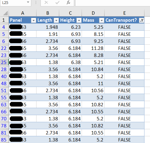
Here is an example of the results:
A sample of the report produced when running the command. This is showing all the panels that failed.
Here are the key server classes:
Summary
Tek1 has the resources and expertise in order to do Precast Panelling jobs fast and
Accurately
These are just the tip of the ice burg in terms of the checks and processes we employ.
Tekla has got model sharing with latest releases. However, nothing like that exists in previous releases.
Now with API plugin from Tek1 you can share member placements on earlier versions. There is no Lic fees to for model sharing to be paid to Tekla.
You as the main modeller decide to farm out member placements to external modellers. You give them a log in and assign the project to the external contractor.
The external contractor models the elements. The modeler selects the elements and users of our API to share the model elements.
The main modeler then users our API to synchronize the model elements with the main model. The main modeler or the contract modeler can now adjust set outs and RLs on their model and the respective model can be synced with full control (accept or reject sync)
Update: This API is not available for sale. We thank you for your interest nonetheless.
Friends, there is no substitute to reading the documentation. The most up to date version of this is located in our Team Drive – but here is a local copy nonetheless.