This is a little utility which connect handrails. It does so if:
1. The handrail block references are parallel to the panel edges, and
2. If they are a minimum 560 mm away from the edges and
3. If they are colinear with each other.
Some lines may be more equal than other lines? The AutoCAD .net API’s EqualTo method may disagree with your interpretation of equality. Here are the results;
We’ve considered a lot of things. Some things still to be improved:
Naming,
Better utilization of the ClosedXML library – because our techniques are quite primitive right now.
Testing (this really should be done first, but no matter).
Further refining the code according to SOLID design principles.
Here is the code thus far:
Ok, that’s certainly a bit better. Still the namining of the classes is quite poor; and we have the dependency inversion issues that we need to fix. Also is there any need to pass in the beams object direction when at the end of the day, we are converting it to a data structure which the printer can understand? Perhaps we should just pass in the printed data structure? We will address these concerns in Part 3 of our refactoring.
Strive to improve the code. Just like this guy is trying to improve his swing. Looks like a fine golfer by the way. probably low single figure handicap, if not scratch.
We will attempt to do something which is seldom done or discussed in Tekla code samples: and that is the very important issue of refactoring code.
1. Start with Tests.
The first thing you need is a good suite of tests. That way you will know whether something has gone wrong or not. It might be tricky doing this since we are developing within the Tekla environment, but I do suppose it’s possible.
Some nice looking steel. The picture has nothing to do with the Tekla API but it’s cool nonetheless.
What is the task at hand?
The user selects some beams.
We then want to collate the following information into various Excel spreadsheets:
Name
Profile
Length and finally Weight
We want two views: the first aggregates the beams by their name and finish, and the second merely lists all the beams selected with the information listed above (length/weight etc).
WARNING: The code is very dirty. There’s a lot of repetition here. And I’ve gone up some cul de sacs incorrectly. But that’s ok. It’s code which works. We can worry about refactoring for another day – in fact, that will make for a very good exercise. Here is a link to where I document the refactoring process.
Clear lines of communication is one of the keys to the success of any organisation.
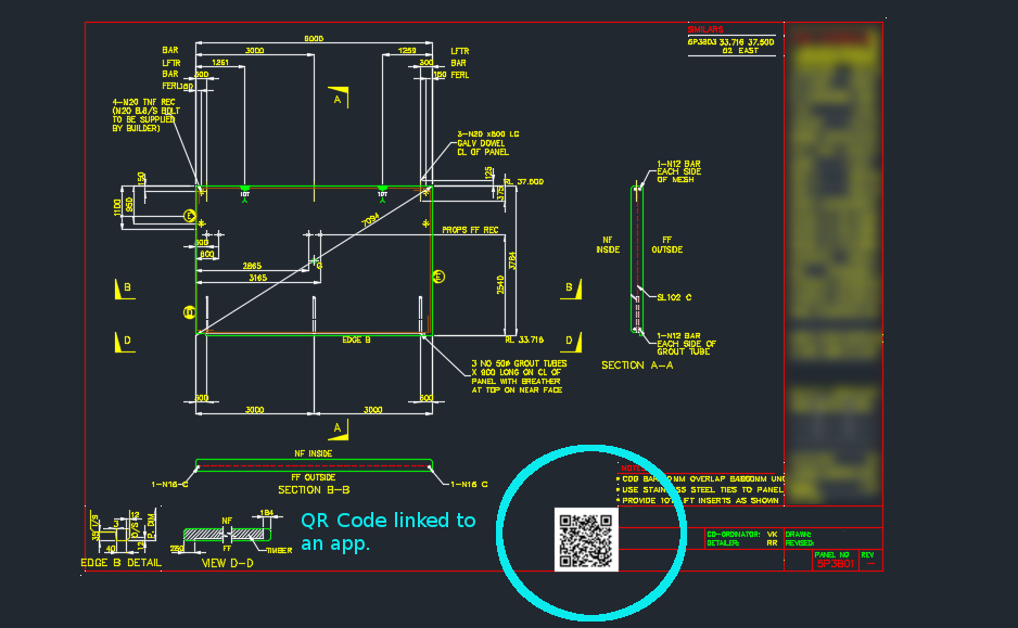
Now you can easily track and record information pertaining to panels with a QR code on each panel drawing.
Here’s how it works:
You scan the QR code, if you’re on the construction site and want to find out specific information about the panel, or if you want to record information about the panel.
Everything is backed by an app on the web.
In this case, we can record things like:
panel status
drafting issues/errors – pertaining to a panel (so the entire drafting process can be improved).
Once the status is recorded, or issues are raised, this is tracked and recorded by the app.
The basic point is that it is very difficult to track and record information pertaining to a panel throughout the entire organisation. Not anymore!
Now you can record and communicate panel specific information to everyone in the organisation.
In the last part we left off having obtained all the bolt distance and placing them in a domain object. In this instalment we will try to export all that data into an Excel Spreadsheet. Please note that the following code is untested – unfortunately there was a lightening storm in Melbourne which short circuited my flux capacitor which means I cannot connect to the TeklaServer – so rather than wait, I thought to get this code out to you.
Which library to write to Excel?
There are many libraries out there: XLS compatible and not:
OpenXML libraries
ClosedXML libraries
NPOI
EPPlus
The consensus is that the worst of the above is still better than using Microsoft’s office interop dll. If you use that approach, you will need to ensure that MS Office is installed in your deployment machine, and secondly, be sure to dispose of all relevant objects. If you forget, then you’ll be leaking memory. This is a very important point.
How to use ClosedXML in your code:
Firstly download closedXML using NuGet Package Manager. That should add the relevant references.
Secondly add the `using ClosedXML.Excel` directives.
Then add the code snippets I’ve provided for you below:
Notes on the code:
* A significant change has been made – we are now filtering the SinglePartDrawings based on: (i) whether they are beams or not and (ii) whether they have the relevant profile – a reader wrote an email asking for this version of the code. I have left the previous version out there as well.
* I’m not an expert with ClosedXML – I just wanted to get the code out there. So it’s a very hackish and non-elegant solution, but I hope it serves to illustrate the point.