Have you ever fallen down a flight of stairs? I hope not! But from experience I can tell you that it’s not a very pleasant one. I slipped as I was walking down – I fell supine, hard, like a hammer on a nail, bang into the corner of the steps. The pain was absolutely numbing – I could walk for about three days, nor could I even roll over in bed for about that same period. Falling down stairs is a dangerous business – and if you’re in the business of designing or fabricating stairs – especially public access stairs, then you absolutely have to get it right. Because if you don’t, then it’s only a matter of time till someone falls. Luckily I was a young man, so I recovered pretty quickly. But if I was an invalid, a fall like that could be potentially life threatening!
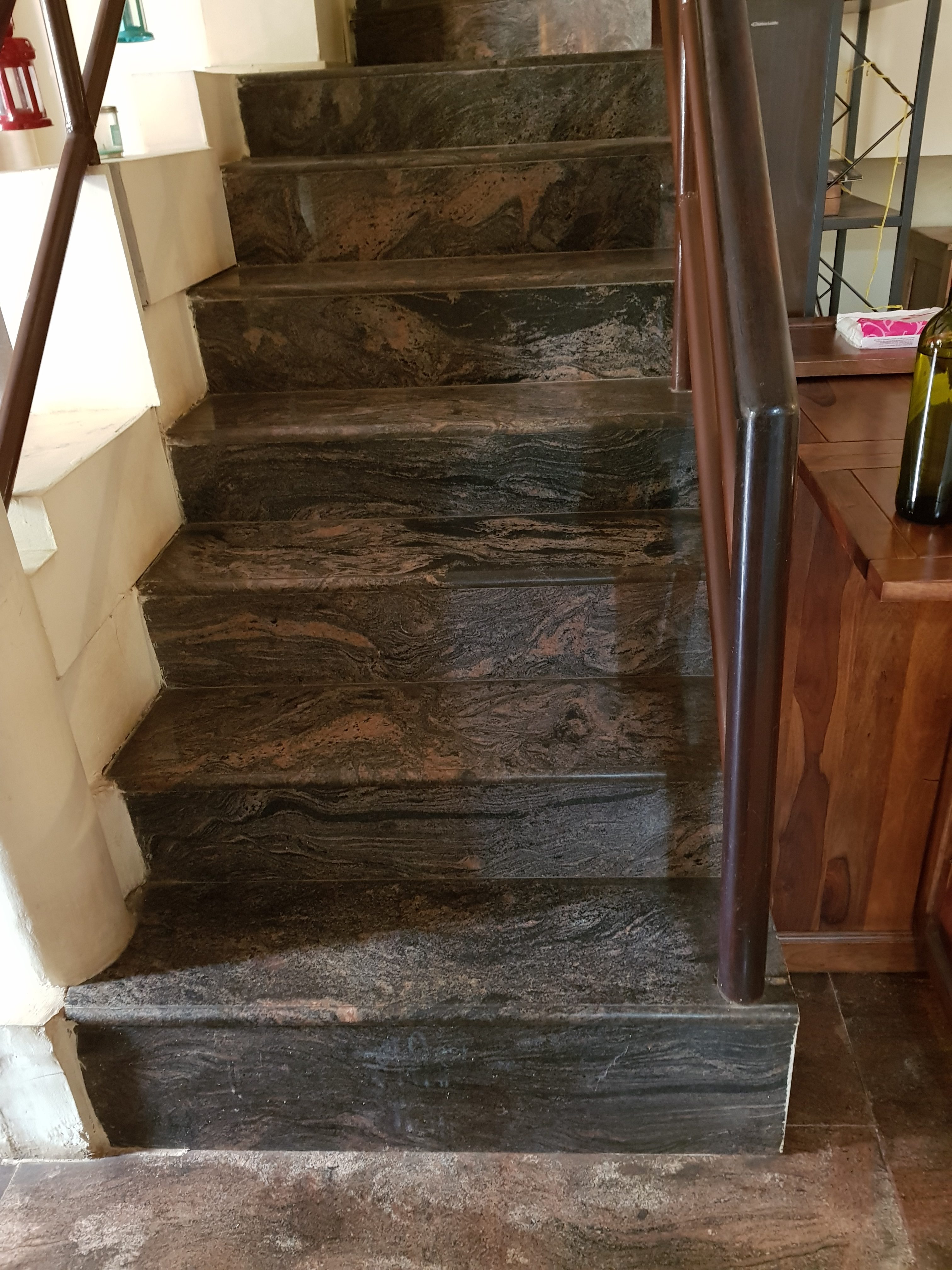
Here is an example of a badly designed stair:
An example of a staircase which was not made according to AS specifications or perhaps any sort of specifications apart from the builder’s convenience I suppose. This type of shoddy workmanship will be the cause of many injuries and accidents. Designing structures according to the specifications mandated is absolutely essential.
The steps are not uniform – they vary in height and length. This is not safe if you are traversing it. It’s easy to misjudge. That’s why when we do the shop drawings for a flight of stairs we check that it’s uniform, that you don’t have too many stairs in a flight, that there’s adequate room, that a child cannot squeeze his/her head in between the treads, etc. I have ascended and descended these steps – and were it not for the handrails, it would be very dangerous. Don’t do steps like this. Here were the measurement from the bottom riser going up:
29 cm
20 cm
20 cm
18 cm
17.5 cm
15.5 cm
The risers vary too much!
Our staff are trained to ensure that their stairs comply with Australian Standards. We’re definitely not the cheapest, but we’ll know if we see a bad design – and knowing that information could save you a bundle.
A pictorial representation of how Entity Framework, in the world of code, would look if it was a corporeal object.
The problem with using a database, when you have another primary source of information, is that the database needs to be updated. Constantly. If someone forgets to update the database, then you will be relying on information that is old/erroneous and not updated. That’s a huge risk. It’s the type of thing that you want to do only if your staff are disciplined, and the gravity of failure is low, should they forget. But if the reverse is true, then you’re sure to eat humble pie, and cause a lot of needless trouble and expense for yourself and all you deal with.
There was a political war over the implementation: I was for using the original database, and the boss was for creating a new one. Accuracy vs speed. Speed won the victory. And I must oblige by constantly updating a database with panel information.
What are these guys doing, you ask? I suspect that they are jigging a line. They are probably doing it this way because they didn’t read the ObjectARX documentation. Well actually, you don’t need to. Just use the poor man’s jig.
I wanted to implement a jig for drawing a Line – but strictly speaking I didn’t want the line itself – I wanted its two points, yet I wanted all the features that come with jigging: snaps, polar tracking, and a nice line leading from the base point to the cursor, which shows you where you were, and where you are going. I was originally going to jig it all myself – and all of this to obtain two coordinates in a manner that would allow the user to see what was actually going on. Jiggig takes a lot of effort. It was only then that I realised I could get the same result, but with a massive short cut:
Here is a poor man’s Line Jig – at the end of it, you’ll have the two points you are after, but without the effort. If required, you can encapsulate all the logic in it’s own class, so that the client doesn’t have to bother too much with the implementation details.
These are steps. When you get to the top, you’ll be an AutoCAD master programmer.
I’ve compiled a list. There’s actually quite a bit involved. I don’t think you can get away with simply not knowing anything about unamanged ObjectARX world. Here is the list below – which I will update. If you see any notable topics which I have missed, please feel free to add a note and I will update the list.
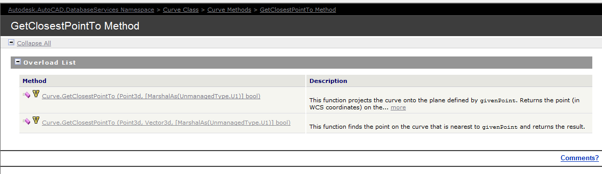
Documentation of the GetClosestPointTo method of the curve object – the overloads are extremely limited. So we have to be somewhat creative in obtaining a solution.
The Genesis of this problem
This is a tricky little problem and I could not find a solution on the forums. So I resolved, upon discovering the solution, to oblige posterity and the public, to publish my findings.
Specific Notes about this problem
Now the following code has been generalised to the specific case of Lines and a non-descript curve (which of course is an abstract base class), but the general principles can be applied to any type of curve.
Notes on implementation
Unfortunately, the curve object exposes a method: GetClosestPointTo, which is only overloaded to accept points and not other curves. In order to deal with this rigmarole we’ll have to first, convert the curve to a `Curve3d` object which is a member of the Autodesk.AutoCAD.Geometry namespace as distinct from the Autodesk.AutoCAD.DatabaseServices namespace.
We have someone who is pointing to the monitor. Makes perfect sense right?
This is largely a replication of what is contained in the documentation without the extraneous (and extremely confusing) intertwining of WPF/WinForms functionality. Personally I believe when engaging in hello world functions that they should be as simple as possible.
I have done as much here.
In time, I will add further details to provide you with some more information on the classes that are used. The main thing to pay attention to here is the FullSubentityPath class as well as the PointMonitorEventArgs.AppendToolTipText(string) method. More details will follow later on. For the moment, parse this code and try to understand what you can:
A physical representation of a Result Buffer outside the world of ObjectARX. hahha.
Unfortunately, and unsurprisingly, the documentation is a little sparse on this point. But somewhere deep within the annals of the AutoCAD documentation I found this little beauty:
Here is the documentation. But for you folks who may find that the link does not work, I will also copy and paste verbatim, what is said there:
The ResultBuffer type is a class that mirrors the resbuf struct defined in the ObjectARX SDK. The resbuf struct provides a flexible container for AutoCAD-specific data.
An Autodesk.AutoCAD.DatabaseServices.ResultBuffer class object is used in much the same way as a resbuf chain. You define a ResultBuffer and populate it with a sequence of data pairs. Each pair contains a data type description and a value. In the managed API, these data pairs are instances of theAutodesk.AutoCAD.DatabaseServices.TypedValue class. This utility class serves the same purpose as the restype and resval members of the resbuf struct.
The TypedValue.TypeCode property is a 16-bit integer value that indicates the TypedValue.Value property’s data type. Acceptable TypeCode values depend on the specific use of aResultBuffer instance. For example, TypeCode values that are suitable for an xrecord definition are not necessarily appropriate for xdata. TheAutodesk.AutoCAD.DatabaseServices.DxfCode enum defines codes that accurately describe the full range of possible ResultBuffer data types.
The TypedValue.Value property maps to an instance of System.Object, and theoretically may contain any type of data. However, the Value data must conform to the type indicated by TypeCode to guarantee usable results.
You can prepopulate a ResultBuffer by passing an array of TypedValue objects to its constructor, or you can construct an empty ResultBuffer and later call theResultBuffer::Add() method to append new TypedValue objects. The following example shows a typical ResultBuffer constructor usage:
using (Xrecord rec = new Xrecord())
{
rec.Data = new ResultBuffer(
new TypedValue(Convert.ToInt32(DxfCode.Text), “This is a test”),
new TypedValue(Convert.ToInt32(DxfCode.Int8), 0),
new TypedValue(Convert.ToInt32(DxfCode.Int16), 1),
new TypedValue(Convert.ToInt32(DxfCode.Int32), 2),
new TypedValue(Convert.ToInt32(DxfCode.HardPointerId), db.BlockTableId),
new TypedValue(Convert.ToInt32(DxfCode.BinaryChunk), new byte[] {0, 1, 2, 3, 4}),
new TypedValue(Convert.ToInt32(DxfCode.ArbitraryHandle), db.BlockTableId.Handle),
new TypedValue(Convert.ToInt32(DxfCode.UcsOrg),
new Point3d(0, 0, 0)));
}
What does all this mean?
I can’t justify an entire post without adding some degree of value: let’s try simplify its meaning a little more. Basically, result buffers are like CLR dictionaries: they are made up of a series of TypedValue objects. These TypedValue objects are like Key-Value pairs which you can fill with different types of data (i.e. AutoCAD data), or even non-AutoCAD data. The values you can use for the Key (in a TypedValue object) are basically that which are specified as DxfCode values.
Result Buffers are:
Made of TypedValue objects.
Typed value objects are like Key Value pairs
Where the key of the TypedValue is a DxfCode and
The value of the TypedValue is any AutoCAD type which corresponds to the DxfCode set as the key.
I hope that’s making some degree of sense? It will be a sad day if such an explanation obfuscates what is written in the documentation (where it exists) to a greater degree than the documentation itself. Anyways, I do hope it helps.
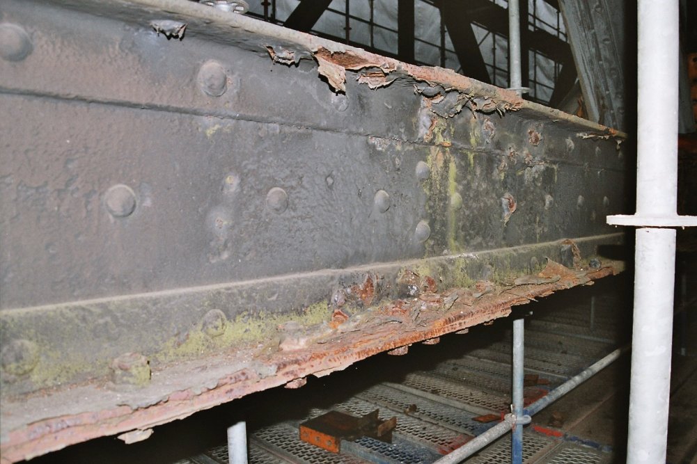
This is a picture of a rusty beam. I added the picture here because it looks cool and for no other reason.
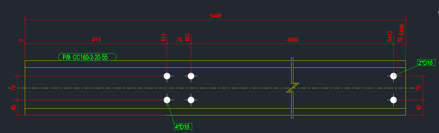
In the last part, we left off having collected the relevant Single Part Drawings that we were after. Hopefully we have applied the correct property to filter out the ‘HEA’, ‘IPE’ and ‘CC’ drawings. We will now focus on part II – extracting the distance of the bolts from the beam’s start position.
Get every SinglePartDrawing which name starts with “HEA/IPE/CC”
Calculate the distance of every bolt distance from the start of the corresponding Single Part. ** This blog post will address Part II.
Write the name of the Single Part and every bolt distance to Excel.
Refactor the code.
I did refactor the code a little bit, so it might not look exactly the same as the last version. The code is pretty self explanatory. But you will note that:
I am projecting the bolt positions along the beam’s vector (defined from the start to end point of the beam).
Therefore we do not need to save and set the transformation plane.
A corollary (and potentially unintended consequence) is that this will capture the bolt positions of all bolts, no matter if they are on the flange of the beam, or on the web etc. This may have some unintended consequences. Again, caveat emptor – programmer beware!
Here is the code in all it’s glory – simply follow the well detailed comments and it should be fairly straightforward. As always, any questions, feel free to ask.
We now have extracted the relevant information. Part III will delve into extracting this data in an Excel format. We will most likely use an OpenXML on other such library for that purpose. That post will come shortly, when I get a spare moment. Till that time, enjoy the following – or perhaps it can be left as an exercise for the user?!
We want the bolt distances of all the single parts.
Every now and again we obtain a request from our readership to tackle a problem. If it is of general interest to the public and given our commitments we do sometimes oblige. Here is one such interesting problem. We will tackle this in three parts, and will focus on part 1 in this blog post.
Get every SinglePartDrawing which name starts with “HEA/IPE/CC”
Calculate the distance of every bolt distance from the start of the corresponding Single Part.
Write the name of the Single Part and every bolt distance to Excel.
Refactor the code.
The first part is easy enough – and the code is pretty self-explanatory. We want to iterate through all the drawings and filter for the specific drawings that we are after.
Here is the code:
In the next part, we will look at obtaining the relevant parts that we want and calculating the bolt distances from the start and end points. And finally, we will look at refactoring the code, because it is a little slow, and also from a maintainability point of view.
An Addendum
I was simply following the instructions of the question without inquiring too far into its purpose. If you actually want to extract NC information via the API – Tekla can very easily do this. But that was not the scope of this particular task – it was to deliver a very specific and peculiar set of requirements to a particular reader, but it is a topic which will be of general import to the public.