This was a question which someone asked.
I accordingly answered it with a code example. The answer is simple:
Ensure that you add `“\X”` as a suffix to the `DimStyleTableRecord.Dimpost` property.
Here is a code example:
This was a question which someone asked.
I accordingly answered it with a code example. The answer is simple:
Ensure that you add `“\X”` as a suffix to the `DimStyleTableRecord.Dimpost` property.
Here is a code example:
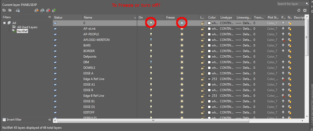
A tyro to AutoCAD will immediately notice that he or she has two options available to him – both of which ostensibly render similar results: freezing a layer and turning it off. But what is the real difference?
That’s the difference and I hope you learned something.

Duplicates are a problem – an expensive problem, especially if you are dealing with hundreds and perhaps even over a thousand panels. Somebody cocks up – usually on the client side – but how are you meant to identify it?
You could manually do it, but then that will more than likely take a long time. Or you could just employ Tek1 to do that sort of thing for you. Here is a video demonstration:
Identify Duplicate Panel Names In Precast Panel Detailing from Tek1 on Vimeo.
Features:
Example of Well Abstracted Code:
It can get pretty annoying zooming and moving back and forth between a panel and another panel. You can eliminate a lot of the panning involved by saving a “View”.
The gif above will show you all.
I hope you learned something!
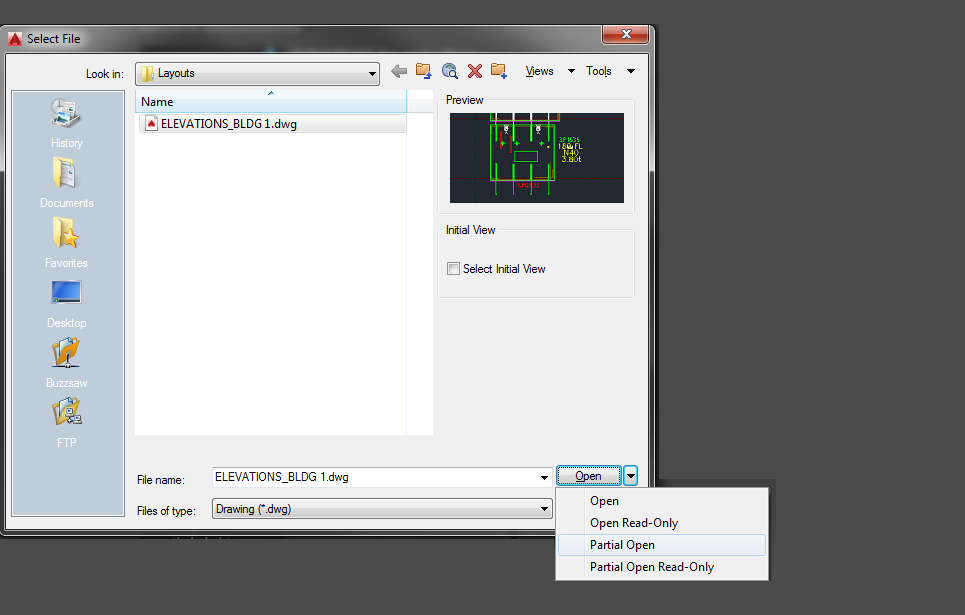
Suppose your .dwg file has hundreds of thousands of entities all over the place – but you don’t want to see all of them at once – or load all of their geometries. This is especially the case when dealing with Bubble Deck layouts. You can only open the things that you need via a partial open. You can now choose and view only the stuff that you want to see. It’s quicker than otherwise.
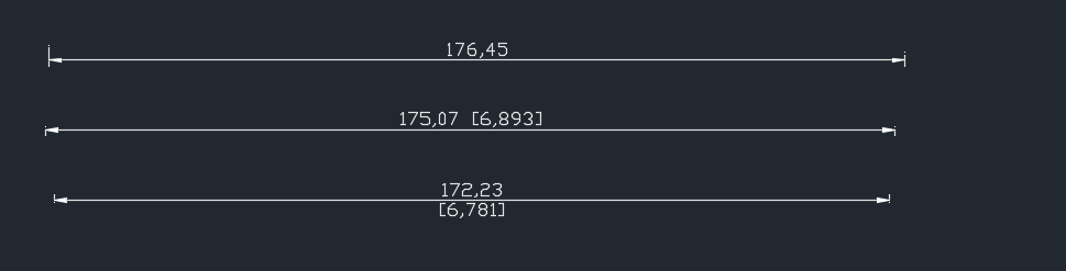
This is big. Huuuuge! I’ve talked before about our ability to easily cross check between the Layout and Shop drawings. Now you can cross check from the other direction – when you are in the shop drawing, you can now check the corresponding panel which exists in the layout.
You can clearly see any differences.
So now if someone moves a ferrule or a cast in plate etc. you will be able to easily see those changes.
It could save you from some expensive errors.
Here is the demo. I hope you enjoy it!
Compare and Import Difference From the Layout Into Shop Drawings from Tek1 on Vimeo.
Features:
Please brush up your basic engineering mathematics, logarithms. Please be prepared with Paper, pen, good internet connection and a calculator.
Test are timed and will close within 1 hour.
Please fill in this form and we will send you a URL, username, and password to take the online test when positions become available.

This post details an important issue in programming (and in the development of solutions which solve certain problems): the problem of human nature. It outlines my experience and the lessons which I have learned. I will share them for the benefit of
our readers.
I had originally created all the data a client needed and more – streamlined and efficiently placed in pivot tables – in neat rows and columns that allow you to configure and query the data to find out anything and everything you need to know. To me it was a no brainer – surely they’d opt for this solution over the earlier inefficient solution. This data basically was a list of items that needed to be ordered, their quantities, and lengths, listed by the panel number which they were to be cast in. It’s like giving you the power of the sun, but in the palm of your hand. It’s amazing!
I presented this solution to the client, hoping that they would appreciate it and understand its value, its beauty and simplicity. It sure beat the old fashioned way by which items were ordered: hand counted and then manually compiled into a table in AutoCAD – of all places – yes you read correctly, in AutoCAD, not Excel or some RDMS. From AutoCAD, revisions are nearly impossible to track, especially when you have thousands and thousands of items to be ordered. And from there, from the AutoCAD drawing, that data is then again **manually** recompiled into another Excel spreadsheet that sits at the client office. There is so much duplication, needless inefficiencies, and the potential to make costly mistakes. It’s crazy!
What if there were revisions to say, 100 panels? Wouldn’t it be handy to know that you don’t need to order an extra 30 or so cast in plates (given they were previously ordered) – and cast in plates ain’t cheap? It’s a walk in the park for a pivot table. But there just one problem: that was not what the client wanted.
Nope: the client wants their data presented in a certain way, in a certain style. Pivot tables are a whole new kettle of fish. The client does not want Excel. The client wants AutoCAD. And moreover, that data must be presented in a certain style: red text, white lines, and the curious anomaly of those sheets having the same data unnecessarily repeated numerous times throughout the same page. Now that’s fine by me. But it raises a very important lesson which is worth sharing:
Would be curious to hear your thoughts.

This is a demonstration of how we use Excel-Add ins and AutoCAD plugins to simplify the process by which order forms are created for Precast panel jobs.
Please watch the below video:
Print Bubble Deck Order Forms from Tek1 on Vimeo.