Showing a sample elevation panel with deliberately misplaced panel elements.
This is big. Huuuuge! I’ve talked before about our ability to easily cross check between the Layout and Shop drawings. Now you can cross check from the other direction – when you are in the shop drawing, you can now check the corresponding panel which exists in the layout.
You can clearly see any differences.
So now if someone moves a ferrule or a cast in plate etc. you will be able to easily see those changes.
It could save you from some expensive errors.
Here is the demo. I hope you enjoy it!
It can work for all clients with only very minor modifications. Very well abstracted out in the code.
It is super fast. Comparing the thousands of elements in each drawing takes a bit of computing power – but with smart algorithms, you can cut down the time.
It works for all sorts of edge cases – what if the panel was made up of arcs, polylines and straight lines – this plugin can handle all sorts of things. It can also handle voids.
We have 2 positions available now at our Koyambedu Office as of 30/03/2019.
You will be required to attend an online test from home. If you pass the test from home, then we will call you for a test in our office in Koyammedu Chennai for further test and interview.
Please brush up your basic engineering mathematics, logarithms. Please be prepared with Paper, pen, good internet connection and a calculator.
Test are timed and will close within 1 hour.
Please fill in this form and we will send you a URL, username, and password to take the online test when positions become available.
If there’s a very high learning curve involved in using your software – chances are that a lot of people simply will not use it.
This post details an important issue in programming (and in the development of solutions which solve certain problems): the problem of human nature. It outlines my experience and the lessons which I have learned. I will share them for the benefit of
our readers.
What happened? What was the problem?
I had originally created all the data a client needed and more – streamlined and efficiently placed in pivot tables – in neat rows and columns that allow you to configure and query the data to find out anything and everything you need to know. To me it was a no brainer – surely they’d opt for this solution over the earlier inefficient solution. This data basically was a list of items that needed to be ordered, their quantities, and lengths, listed by the panel number which they were to be cast in. It’s like giving you the power of the sun, but in the palm of your hand. It’s amazing!
I presented this solution to the client, hoping that they would appreciate it and understand its value, its beauty and simplicity. It sure beat the old fashioned way by which items were ordered: hand counted and then manually compiled into a table in AutoCAD – of all places – yes you read correctly, in AutoCAD, not Excel or some RDMS. From AutoCAD, revisions are nearly impossible to track, especially when you have thousands and thousands of items to be ordered. And from there, from the AutoCAD drawing, that data is then again **manually** recompiled into another Excel spreadsheet that sits at the client office. There is so much duplication, needless inefficiencies, and the potential to make costly mistakes. It’s crazy!
What if there were revisions to say, 100 panels? Wouldn’t it be handy to know that you don’t need to order an extra 30 or so cast in plates (given they were previously ordered) – and cast in plates ain’t cheap? It’s a walk in the park for a pivot table. But there just one problem: that was not what the client wanted.
What was the lesson to be learned?
Nope: the client wants their data presented in a certain way, in a certain style. Pivot tables are a whole new kettle of fish. The client does not want Excel. The client wants AutoCAD. And moreover, that data must be presented in a certain style: red text, white lines, and the curious anomaly of those sheets having the same data unnecessarily repeated numerous times throughout the same page. Now that’s fine by me. But it raises a very important lesson which is worth sharing:
Don’t depart too far from what your users are used to. If you do, they simply won’t use it or appreciate your solution. In this case, the pivot tables were too big a leap. It is not easy and it’s complicated. It’s like presenting to users Git, and telling them that it will solve all their version control problems – when those users are used to simply “Saving As” – as their version control system. It’s too big a leap and too far a learning curve.
Give them what they want: Your customer wants red text. Give that to him. Your customer wants white lines: give that to her. Sure, you have an obligations to suggest other alternatives which may be of benefit to them – but at the end of the day, it’s their call. Don’t argue with them about what is best for them: shut up and simply give ‘em what they want! This is the most important lesson that I learned.
Ordering thousands of items in a layout is not easy. Order efficiently with Tek1!
This is a demonstration of how we use Excel-Add ins and AutoCAD plugins to simplify the process by which order forms are created for Precast panel jobs.
Tek1 Sign MOU with Saudi Arabian Company Freih Bin Owaidha Al-Qahtani Sons Co. Ltd, Alkhobar.
Freih Bin Owaidha Al-Qahtani Sons Co. Ltd will be representing Tek1 in all business in Saudi Arabia for detailing of Structural Steel and precast panels. Local office with technical staff will be established to cater to major clients in Saudi Arabia so projects can proceed smoothly and communication hurdles can be removed.
Contact Details in Saudi Arabia.
Phone – +966 13 865 4760,
email info@alfreih.com.sa,
P O Box 3073, Al-khobar 31952
Saudi Arabia
How to avoid grating and chequred plate errors being wrong , due to the view being wrong.
We have a copped a few of these errors where the chquered plate (or grating) was drawn upside down.
How to counter measure: add orientation part cut on the plate
The way to counter measure this error is to put an orientation part cut on the plate. Make sure on the part drawing the full lines of the cut is shown. Cut will have to be on the top surface of the plate and must not penetrate to the other side.
We want to dimension certain objects in the drawing.
First we need to identify the objects that we want to select. Since the Tekla Closed Open API doesn’t have much of a picker exposed, we would be forced to select the objects we need before running our command. We can do so with a pick first selection (to use the AutoCAD terminology).
(Unfortunately it’s not a block table record dictionary definition – but it kind of is :))
Some how or other all the block definitions associated with a drawing were not defined on layer zero – this is less than ideal. I guess it goes right up there with another instance I heard about: (i) about drawing everything in paper space, or layer zero, for example.
Accordingly, it feel to me to change all the block definitions. I could foresee that there might be some other requirement associated with changing all the block definitions, so I thought it apposite right now to employ the strategy pattern to solve the problem.
Here is the code in its entirety. I like using LINQ, it’s concise and efficient, so I beg the patience of those whose views differ:
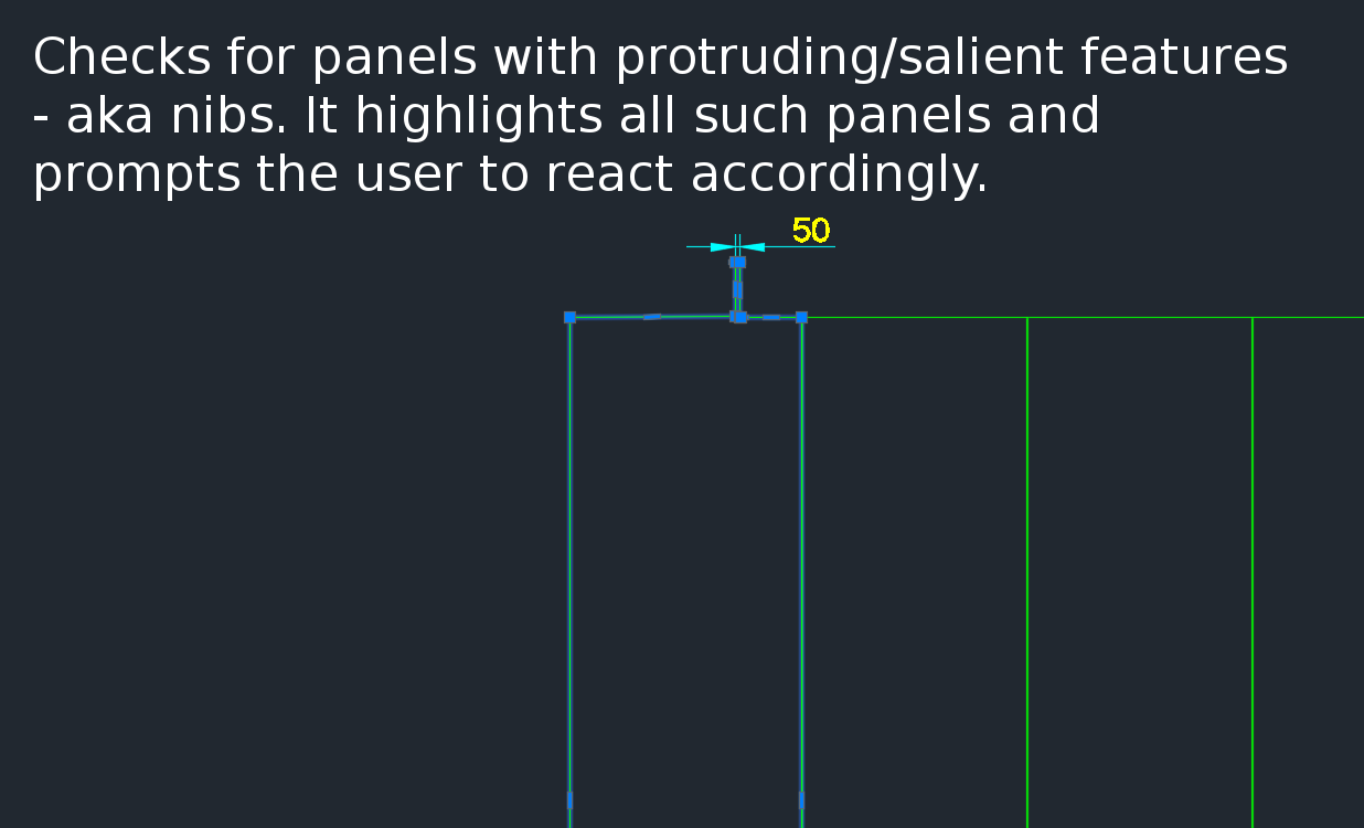
A gif showing how easy it is to check for nibs on bubble deck slabs using my command. There are certain panels which we have that have protruding elements – salient features. These can be problematic if they go to production unnoticed. Given there are entire teams of people doing things, it can be hard to track – people forget that they cannot draw a panel with such a dimension.
This is a plug in which enables one to easily identify all such panels with nibs like this:
There is a need to identify panels with protruding features because they could be problematic if fabricated.