The AutoCAD .net/ObjectARX APIs have a handy feature all the pick first selection. This means that prior to running a command, the user is able to select some objects in the model. The command is then able to use these objects. The question is, how to obtain a selection of objects using the Tekla API – prior to running your plug-in?
The object of a Tekla Application is to ensure that things go smoothly on the construction site. You can see the organised chaos that is here. Avoid the real chaos. Plan ahead.
For the newbie this post shows how to set up a Tekla Project.
Let us assume that you are creating a WPF desktop Application. You could also just as easily create a console application – I often do this if I simply want a quick and dirty way to test code.
Here’s the problem. You are viewing a Tekla drawing. But you have no idea what you are looking at, or where it is. This macro will take you to that very assembly in the model. It’s actually quite handy. And here is the previous post where I made allusion to the facility (you’ll find a video demonstrating its use):
Tekla licenses are pricey. About $30k + maintenance per license. What if I told you that you needed 30-50% less licenses than you currently hold. That’s a huge cost saving, isn’t it?
If you only need 5 licenses (as opposed to 10), then you’ve saved $150k instantly, plus maintenance.
AutoCAD licenses are significantly cheaper.
But if only the work you did in AutoCAD could be transferred into Tekla? That would save you some licenses. That’s just what I’ve done here in my latest project. Now a significant portion of any modelling job can be done in AutoCAD and simply imported into Tekla.
Interoperability will also help improve the quality of your work: it’s tough finding people who are highly skilled in Tekla. What if I told you that you could use an AutoCAD draftsperson instead of someone well versed in Tekla, to do the same job? Now you have a potentially infinite pool of candidates to draw from.
I’d love to be able to help. Just call or email us.
How to Download Tekla Catalogues (or Catalogs):
You need to download the catalogue because the interop DLL connects to the catalog. Without it, we cannot verify that your profiles actually exist in Tekla.
We continue to release our in-house precis on Stair way construction. Reading the standards is terribly tedious so we have developed a way to easily cross check the requirements and to make sure that stairs are built according to standards.
Unfortunately it’s too common for us to see designers produce drawings which simply do not comply to the required standards. So it is of the utmost importance that fabricators are able to: (i) know and understand the standards and to independently verify that their drawings do comply. Only a fool would 100% trust in an architect to draw to standards – we’ve seen it way too often. You, the fabricator have to check everything yourself. Here are some of the in-house memos that we use to ensure that our stairs always comply:
We wish to share it with the world – and we hope it helps you immensely:
There seems to be a lot of confusion with folks about the difference between using the AutoCAD .net API vs the COM Interop API. They both hope to do the same things, but via different ways. Given a choice, I’d always recommend using the .net API because it is much more powerful.
In process – .net API
This means that the user has to first open AutoCAD. i.e. double click on the AutoCAD icon and start up AutoCAD. once AutoCAD is open and a drawing is opened, then the user has to type in a command: “NETLOAD” and has to select the a file – the result of all your programming/coding efforts. once that file is selected the user then has to run the command “AddLine”. the command will run as you have coded it. in order to do it this way you will need the .AutoCAD net API
Out of Process – COM InterOp
In this case, you don’t necessarily have to manually open AutoCAD up. you create your own program, and you open it (much like you would open MS word etc) and your “AddLine” command would run without you, as a user, manually opening AutoCAD and netloading etc.. if you’re going down this path you need to use the COM interop API.
Using Both
If you really want to use the .net API, but did not want to manually netload, then you can use a combination of both of the above:
From the documentation:
If you need to create a stand-alone application to drive AutoCAD, it is best to create an application that uses the CreateObject and GetObject methods to create a new instance of an AutoCAD application or return one of the instances that is currently running. Once a reference to an AcadApplication is returned, you can then load your in-process .NET application into AutoCAD by using the SendCommand method that is a member of the ActiveDocumentproperty of the AcadApplication.
As an alternative to executing your .NET application in-process, could use COM interop for your application.
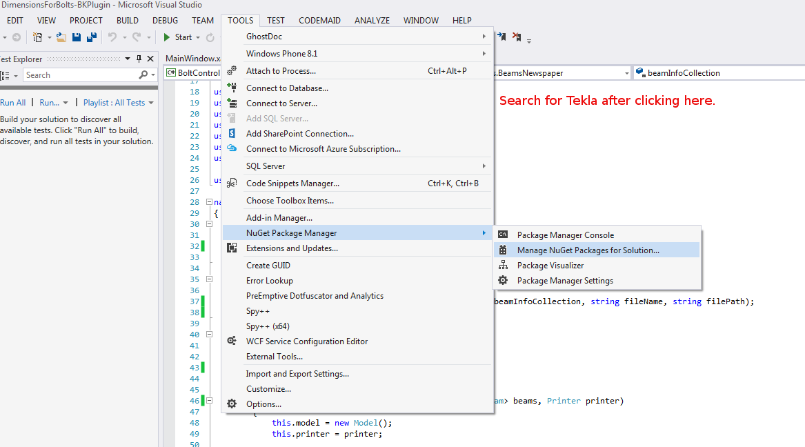
Wouldn’t it be handy if we could pro grammatically insert reference models into Tekla? Well you can now do so quite easily. And if you want to see a video demonstration, here it is:
Here is the code which does the hard work. (You will of course add the appropriate references and directives):
This is an example of a hello world program which dimensions a beam. I found this code in the Tekla Drawing Samples folder.
You can see it in action here:
How to dimension a beam using the Tekla Open API (c#)
Let’s walk through it:
We have to get the relevant drawing.
Then we have to get the relevant part we want to dimension.
Then we get the view associated with the part.
We save our current transformation plane, and we set a new transformation plane to the particular view’s display coordinate system.
From here, get the part’s identifier and we select the ModelObject in the model itself – to get the relevant coordinates of the Beam we want to dimension.
Once we’ve used the identifier to get the Beam we are after, and to get it’s relevant parts then we create the dimension.
Remember to save back the original transformation plane.
Note: if you insert the dimension then I obtained an exception. I don’t think you need to insert dimensions when working on drawings.
Note 2: if you forget to save the transformation plane back to the original, then you will find that you dimensions will go wacky, next time you run the command. Always remember to leave things as you found them!
Note 3: You have to have the beam in the same plane as your view otherwise it won’t draw the dimension.
