Author: GH

  • From Missed Details to Valuable Lessons – A Take-Off Journey at UTAS Stadium Redevelopment

    From Missed Details to Valuable Lessons – A Take-Off Journey at UTAS Stadium Redevelopment

    Scope of the Project

    We were initially requested to prepare a material take-off and model for the UTAS Stadium Redevelopment project. The scope clearly included handrails and balustrades for multiple areas.

    Jobs like this are inherently more complicated than standard steel take-offs. They often require:

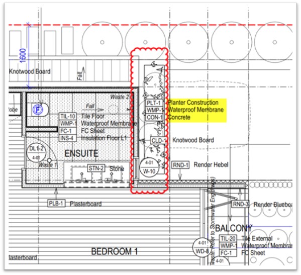
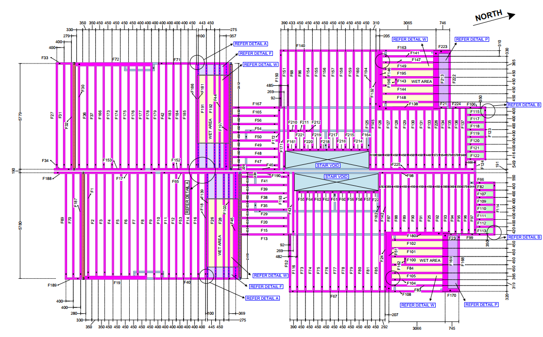
    • Detailed coordination between architectural and structural drawings
    • Consideration of site-specific conditions, such as existing structures that may need rust removal and recoating
    • Identification of non-typical items like steel grating over EAs, which may only be mentioned in notes—not shown in drawings
    • Understanding what is in scope and out of scope, especially for existing vs. new elements

    Example: In other jobs like Respect Care Avonlea, the scope required rust removal and recoating of existing steel. These unique elements must be clearly marked as in or out of scope so the person quoting knows how to price it.

    Also, it’s important to remember that not all steel items are drawn with lines. Some only appear in notes.

    Initial Submission & Review

    Our team submitted the initial take-off. However, during review, Mr. Koshy pointed out that handrails and balustrades were missing.

    👉 This was a valuable reminder that some clients require these items, especially when they’re a focus of the job, while others may choose not to quote on them. Knowing what matters to each client is essential.

    Given that this take-off was for quoting purposes, accuracy was vital. Even a small oversight could result in:

    • Financial miscalculations
    • Client dissatisfaction
    • Loss of trust or future jobs
    • Reduced team incentives

    This feedback helped us pause, reflect, and improve our approach for the future.

    Why Accuracy Matters in Take-Offs

    This wasn’t just a drawing task—it was a cost-based take-off used for budgeting and quoting. An error in such cases can:

    • Lead to incorrect cost estimations
    • Affect the project’s financial feasibility
    • Create production issues if the quote is rejected
    • Ultimately impact our credibility and incentives

    Moreover, certain items – like balustrades, stairs, and grating – are intricate and time-consuming to fabricate. These should not be quoted on a tonnage basis. It’s important to flag such elements to clients so they can be quoted separately and priced appropriately.

    Issues with the Take-Off

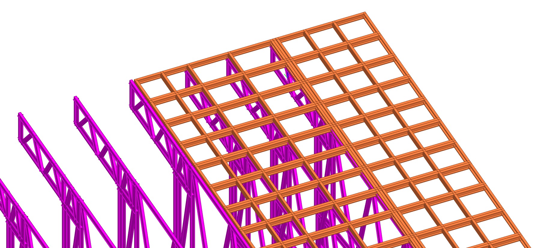
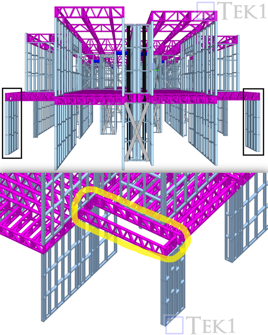
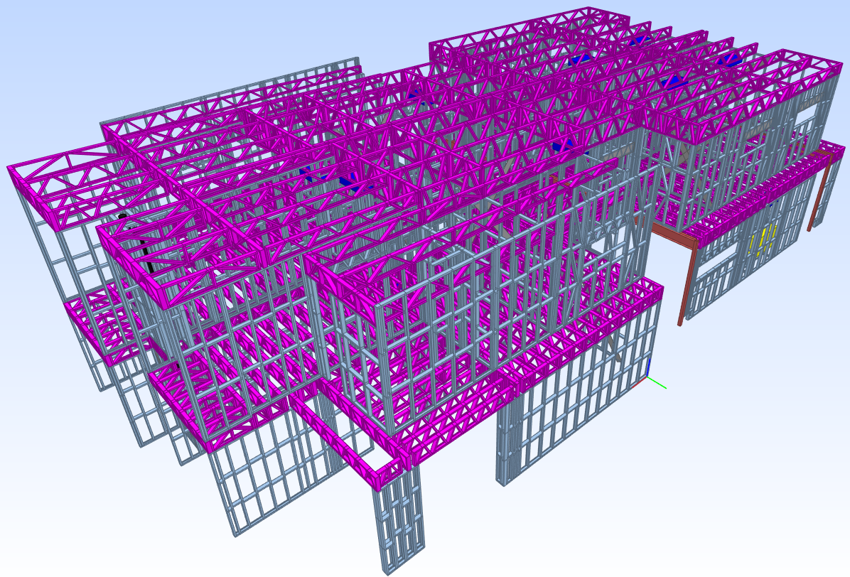
    Further review revealed that purlins and bridging members were missing. These were likely deleted during the cleanup process (e.g., using OVERKILL) without a proper post-cleanup check.

    A senior detailer shared three essential lessons that helped us improve:

    1. Double-Check After Cleanup

    Tools like OVERKILL are useful for removing duplicates, but they can unintentionally delete important steel items.

    Always:

    • Check the model space thoroughly after cleanup
    • Re-import or re-check structural drawings to confirm all members are intact
    • Visually verify all key components before finalizing the take-off

    2. Understand the Scope Clearly Before Starting

    Don’t jump into modelling or marking up without:

    • Carefully reading the client’s request and job brief
    • Noting special requirements such as rust removal, coatings, or integration with existing structures
    • Identifying what’s included/excluded from scope (e.g., stairs, handrails, balustrades, fixing brackets, grating)

    3. Follow Disciplined Modelling Practices

    A clean and organized model helps avoid confusion. This includes:

    • Using correct layer management
    • Extending beam lines to column blocks or grids
    • Using proper naming (e.g., RODXX for rod members in schedules)
    • Keeping the model aligned with architectural and structural references

    Key Learning Points

    We’ve compiled the following key tips from this project and past experiences:

    • Check material grades (e.g., use G450 for purlins and bridging if noted).
    • Always read both structural and architectural notes—some items exist only in notes.
    • Compare drawings -they may not match exactly.
    • Mark PDFs clearly during take-offs to show what’s included.
    • Flag special or intricate items like stairs, balustrades, grating – these are not suited for tonnage pricing.
    • List all exclusions clearly.
    • Mention that take-offs are rough estimates, and clients should verify quantities.
    • Follow consistent modelling practices for clean reporting and review.

  • Smart Framing Decisions in LGS: My Experience at Mickleham Child Care

    Smart Framing Decisions in LGS: My Experience at Mickleham Child Care

    I recently worked on a Light Gauge Steel (LGS) detailing project for a single-story building. Mickleham Child Care. The project involved a 6° sloped metal roof, supported by 2-inch top-hat trusses.

    Refer the below image:

    The building also had a roof overhang on both the top and bottom eaves, which needed proper support framing.

    Refer the below image:

    To cover the overhangs efficiently, I proposed a hybrid roof concept, combining roof trusses with a roof frame. The client reviewed and approved this concept, and I prepared the framing layout accordingly.

    Challenges Faced During Detailing

    As a designer and detailer, I always try to provide practical solutions based on the information available, keeping in mind both structural logic and constructability. However, as I’m not a licensed structural engineer, I work within the limits of what’s acceptable from a detailing standpoint.

    After submitting the overhang frame design, we had a Teams meeting with the client and their team. They shared a few valuable suggestions to improve stability:

    • Use double noggings for better bracing:
      The initial design had single noggings, but the client pointed out that double noggings improve lateral stability, especially in wind-prone regions or when the overhang is long. Doubling up helps reduce flex and provides better load distribution.

    Refer the below image:

    • Use triple studs at key points:
      At certain locations, studs were positioned directly above supporting members or points bearing higher loads. The client recommended triple studs to prevent buckling and improve vertical load transfer in those critical areas.

    Refer the below image:

    • Re-orient the overhang frame layout:
      Initially, I had vertical members as studs and horizontal members as noggings. The client suggested a reversal — horizontal members as studs and vertical members as noggings — so that the framing better supported the roof sheeting direction and provided more consistent strength along the overhang.

    These insights from the client were genuinely helpful and added value to the final outcome.

    Practical Constraints and Adaptation

    Initially, I had created the frame using the Scottsdale software, which by default builds vertical studs and horizontal noggings. To meet the client’s updated request, I had to manually revise the layout in the Scot simulator, which took some additional time and effort. I explained this to the client, and they understood that software limitations sometimes require a manual approach.

    While making these changes, I also adjusted the truss height to match the roof RL ensuring that the roof frame sitting above the truss aligned perfectly with the original design elevation. The final result was a stable, clean solution that maintained the intended levels and supported the overhang well.

    Reflecting on a Similar Experience

    After this session, I revisited an earlier job I worked on – Lot 202 Mount Keira Rd, Mount Keira – where I had used a similar overhang framing concept. That job was successfully completed on site without any issues, and the detailing approach was almost the same as my original proposal in this current project.

    This comparison helped me realize that different clients can have different expectations, even for similar framing problems. It’s not always about what’s right or wrong – it’s about understanding the specific needs of each project and adapting to them.

    What I Learned

    This experience was a strong reminder of a few key things:

    • Client feedback is essential — it helps enhance and refine design decisions.
    • Software is just a tool — manual adjustments are sometimes necessary to suit real-world conditions.
    • Every project is a learning opportunity, even when the problems feel familiar.

    I’m glad this task helped me explore more about overhang framing logic, client coordination, and working beyond default software configurations. I’m sharing this in the hope that it helps someone working on similar LGS roof detailing situations.

  • 🚧 Lessons Learned from the Site: Smarter LGS Detailing for Better Builds!

    🚧 Lessons Learned from the Site: Smarter LGS Detailing for Better Builds!

    🧠 1. Frame Size Matters – Don’t Overlook Transport Constraints 

    • Truss heights hit up to 3m and lengths extended to 10m – something that could change based on client and transport feasibility. 
    • Wall frames also touched 3m in height and 5m in length – be sure to check if it fits the truck before detailing. 
    • Roof overhangs? Review them early to ensure they’re compatible with transport or you’ll risk on-site chaos. 

    ✅ Tip: Always check transport feasibility during quoting and in RFI#1

    ✂️ 2. Splitting Tall Walls – Think Before You Frame

    • External walls taller than 3m should be split during design. 
    • Confirm site handling options – are cranes available, or will it be lifted manually?

    ⚠️ Don’t assume! Discuss early to avoid rework and surprises on-site. 

    🧩 3. Design Features for Roof Panels & Coordination with MEP for Wall Cutouts 🛁

    • Before locking in the wall layout, always confirm plumbing cutouts and vent pipe locations with the client, especially in WET areas.
    • If these aren’t aligned early, it can cause major trouble onsite — including last-minute frame cutting.

    For Roof Frame like overhangs:

    • Rafters should be designed as doublers (to add strength).
    • Rafters must be perpendicular to the wall.
    • Noggings should run parallel to maintain overhang stability and simplify installation.

    🔍 These small details make a big difference for smooth execution.

    🚛 4. Confirm Transport & Lifting Method Early

    • Every frame size should be checked for transport in RFI#1.
    • Clarify lifting access – Is there a crane or only manpower?

    🏗️ 5. Large Trusses – Assess or Be Stressed 

    For long trusses that might need splitting: 

    • Evaluate engineering requirements early – if a truss fails, it’s not on us, it’s an engineering issue.
    • Consider onsite assembly time, weight, and transport limitations in your quote.
    • Flag “suspect trusses” during quoting with buffer for iterations.

    🧠 Smart Detailing = Fewer Site Surprises

    📄 6. Quote Smart – Define Scope Clearly

    • Don’t quote blind. Wait for all necessary drawings and details.
    • Add buffer for unknowns and clarifications.
    • Clearly state we follow the provided architectural and structural drawings. If things change later — that’s a variation.

    🔄 7. Variation Handling – Get it in Writing

    • Raise a variation immediately for any change that occurs after quoting.
    • Pause all work on the affected section until written client approval is received (or the variation is rejected).
    • If there’s a delay — pick up the phone and speak directly with the client. Clear communication is key to minimizing disruptions.
    • To alert the client that a change has happened, and that there is a delay in the program.

    💡 8. Our Design Suggestions – Add Value and Help Your Client Cut Costs

    If we propose design improvements (e.g., optimizing the LGS frame layout), they should be quoted as added value.

    When working off client-supplied drawings, and we identify missing details or unclear sections:

    • We can submit proposals for improvement.
    • If this was clarified in the quote, it is already within our scope — no need to raise it as a variation.

    Smart detailing isn’t just about execution — it’s also about helping our clients save time and money.

    🧱 9. Client-Driven Design Changes – That’s a Variation Too 

    Any change the client makes for ease of installation or cost saving must be quoted as a variation

    📋 LGS Project Checklist (for Detailers & PMs)  

    ✔️ Confirm frame size limits (wall/truss) with client 
    ✔️ Review transport feasibility and crane availability 
    ✔️ Request complete architectural, structural, and MEP drawings 
    ✔️ Identify special features (cutouts, splits, overhangs) early 
    ✔️ Define scope clearly – design vs. detailing only 
    ✔️ Include buffer time for potential RFI clarifications 
    ✔️ Document all design and client-driven changes 
    ✔️ Conduct internal reviews before client submission 
    ✔️ Flag and assess suspect trusses during quoting

    💬 Final Thoughts 

    Whether you’re a detailer, project manager, or fabricator, I hope this blog helps you:

    • Spot issues early
    • Avoid costly site changes
    • Deliver smoother, smarter LGS solutions

    📢 More Coming Soon 

    We’ll continue sharing more real-world LGS insights, including: 

    • 🧠 “Can You Spot the Problem?” detailer challenges 
    • 🛠️ Cost-saving ideas we’ve implemented 

    Stay tuned — and let us know if there’s a specific LGS topic you’d like us to cover! 

  • The Power of Coordination: Elevating Project Success with Steel & Precast Alignment

    The Power of Coordination: Elevating Project Success with Steel & Precast Alignment

    🚀 The Power of Coordination: Elevating Project Success with Steel & Precast Alignment 🌟

    In complex construction projects, effective collaboration between steel and precast detailing teams is crucial. Proper coordination ensures smooth project workflows, minimizes delays, and reduces unnecessary costs, ultimately benefiting the client. During our recent team meeting, we explored specific challenges and solutions for optimizing the coordination process.

    Here’s a comprehensive breakdown of the key strategies discussed, along with insights into how we plan to implement them for better efficiency.


    1. Clear Communication on Structural Changes

    • Challenges: Both the steel and precast teams base their work on structural and consultant drawings, but adjustments often arise during the practical implementation. These changes can significantly impact project timelines if they aren’t communicated promptly.
    • Solution: Any modifications in the steel model must be shared with the precast team, allowing them to update their model and drawings accordingly. This is essential to avoid rework and maintain alignment. Our MD emphasized the importance of discussing changes before implementation and ensuring they are approved to minimize unnecessary adjustments.

    2. Model & RFI Exchange Protocols

    • Issue: Delays can occur when teams do not exchange their models and RFI’s efficiently, leading to inconsistencies between steel and precast elements.
    • Solution: To streamline coordination, the precast team should provide the completed model to the steel team, and vice versa. Regular model and RFI’s exchanges help both teams stay in sync and prevent potential clashes in the final stages of detailing.

    3. Setting and Meeting ETA Expectations

    • Importance: The steel team coordinator or the precast team should actively communicate expected completion dates. This mutual accountability is essential to ensure each team is working on schedule.
    • Proposed Workflow: Establishing ETA checkpoints and regular updates will keep both teams informed and accountable, promoting smoother project progression.

    Consequences of Poor Coordination

    When coordination is inadequate, the project risks delays and escalated costs. Here are some potential pitfalls if best practices aren’t followed:

    • Project Delays: Misaligned timelines between steel and precast can cause setbacks, leading to extended project durations.
    • Waste of Resources: Inefficient communication can lead to rework, wasting valuable time and effort.
    • Unplanned Variations: When models are not aligned, variations can arise, leading to costly adjustments for the client.

    Our Key Directives for Improved Coordination

    Highlighted the following directives to improve coordination between steel and precast:

    • Establish Clear Responsibilities:
      It’s essential to specify in the initial RFI who will handle the steel detailing and who will coordinate between the two teams. Clear assignments will create a smoother workflow and enhance accountability.
    • Confirm Internal or External Steel Detailing:
      Knowing whether steel detailing will be done in-house or by an external party ensures everyone is aligned on responsibilities, reducing potential workflow disruptions.
    • Reduce Rework Through Precise Coordination:
      By following these practices, we can eliminate rework and improve project efficiency.

    Future Blog Insights:
    Benefits of In-House Steel and Precast Detailing

    Finally concluding thoughts highlighted the advantages of having both steel and precast detailing by Inhouse. Should the precast team win the job, they can propose in-house steel detailing as well. This approach offers several benefits, which we’ll explore in-depth in our next blog. Stay tuned for more insights on how integrated in-house detailing can drive smoother workflows, lower costs, and ultimately enhance project success.


    Final Thoughts

    Effective coordination between steel and precast teams is foundational to project success. With clear communication protocols, responsibility assignments, and regular model exchanges, we can set a new standard for collaborative project workflows. By continuing to improve these processes, we aim to offer clients timely, cost-effective, and high-quality detailing solutions.

  • Light Gauge Steel vs. Traditional Materials: A Quick Comparison

    Light Gauge Steel vs. Traditional Materials: A Quick Comparison

    Light Gauge vs Wood vs Concrete? Let’s examine the pros and cons:

    1. Strength, Durability and Preference:

    • LGS: Reasonable strength (for residential loads), resistant to: termites, and rot (but is susceptible to rust – in the long term). Neither wood nor steel does well when exposed to water. Light gauge can be “squeaky”
    • Wood: Susceptible to decay, rot and termites. Is very stable.
    • Concrete: Very strong. Not commonly used for residential single storey houses.

    2. Speed and Cost:

    • LGS: Prefabricated off-site, allowing quick assembly on-site. This reduces labour costs and project timelines significantly. LGS is great if your building site is remote, and it is difficult to procure tradespersons: most of the work can be fabricated in a workshop in a metro area – and then transported to the remote location, where it can be assembled with comparatively minimal labour.
    • Wood: Often cheaper initially, but long-term costs can rise due to maintenance requirements. The tendency is to cut on site.
    • Concrete: Often more expensive due to labour, planning, reinforcement and trucking. Is suitable for high rise structures.

    Conclusion

    LGS does well in terms of speed of construction. Traditional carpenters who cut and erect on site –  may take many months. LGS beats the pants of this mode of construction. Entire houses can be framed in a few weeks. Note: it is also possible to prefabricate wooden frames and erect on site.
    Weigh up the costs and benefits accordingly.

    At Tek 1, we provide Light Gauge Steel detailing services.

  • Lot 202, Mount Keira Road, Mount Keira

    Lot 202, Mount Keira Road, Mount Keira

    About:

    • A Two-story dwelling.
    • Roof truss: 9m-long sloped ceiling.

    Problems Solved:

    • Utilized a panel roofing system for the overhang to match the truss roofing system.
    • Conducted precise truss engineering analysis using the Scottsdale 700mm machine series.
    • Included point load calculations to determine upward and downward load transfers from the roof to the floor.
    • Incorporated a set-down in the floor joist to accommodate the bathtub and calculated its load-bearing capacity.
    • Proposed the reduction of structural steel, which was approved by the engineer.
    • Designed wall cutouts and tolerances for accessing the steel column base plate within the slab.

    Project Highlights

    Designed wall cutouts and tolerances for accessing the steel column base plate within the slab

    Incorporated a set-down in the floor joist to accommodate the bathtub and calculated its load-bearing capacity

    Produced precise slab drawings with details based on the LGS model

    project gallery

  • Lot 57, Sturdee Street, NSW

    Lot 57, Sturdee Street, NSW

    About:

    • two-story residential building in Sturdee Street, Towradgi NSW
    • We cut eliminated steel beams and replaced them with LGS joists and columns in order to cut costs. We proposed a design which our approved.
    • To facilitate proper load transfer from top to bottom, we organized the floor trusses and roof trusses with a uniform spacing, which also aided in minimizing the use of steel.
    • This project encompasses 9595 meter of light gauge steel roll former, comprising 11.5 tons of steel.

    Project highlights

    We proposed a design change to replace a concrete column for an external planter box with a double-wall LGS column.

    Subsequently, the client approved the proposed change and also opted to replace the concrete planter box with an LGS planter box.

    We provided an exclusive floor joist layout and detailed views for critical areas.
    To avoid error during installation.

    project gallery