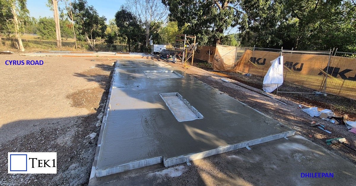
Precast detailing projects show case precast projects detailed by Tek1 Pty Ltd.
These projects are in Melbourne, Sydney, WA
We have detailed over 10,0000 panels over 12 years.
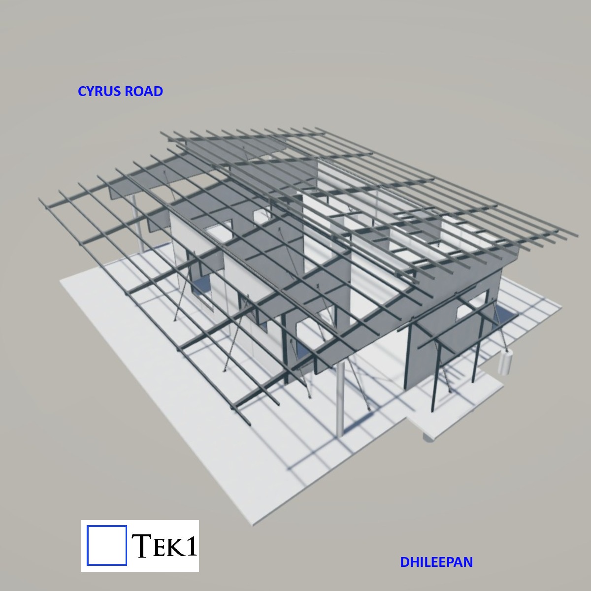
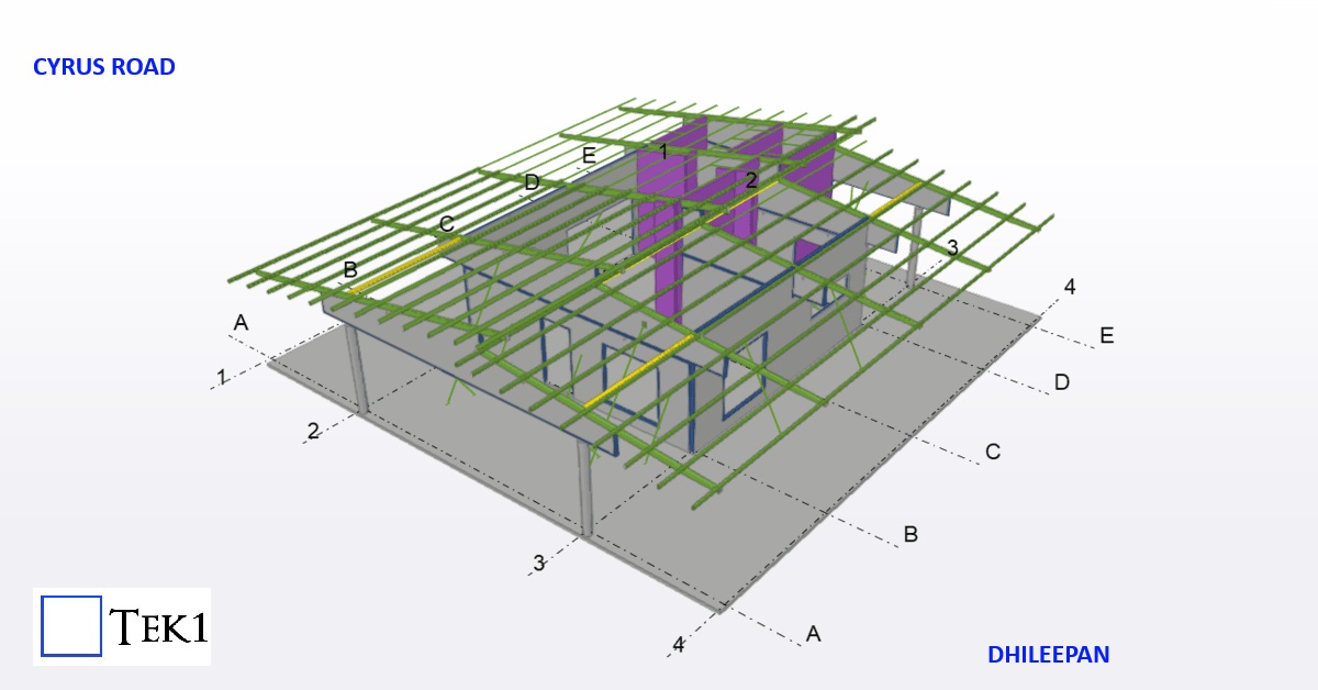
This residential project showcases an innovative hybrid construction approach, where the entire building is formed using just 11 precast composite panels and a few stud walls. Each panel consists of a fabricated steel perimeter frame filled with cast concrete, creating a strong, integrated structural unit. On site, the panels are positioned and welded together through their steel edges, forming a rigid, continuous structure.
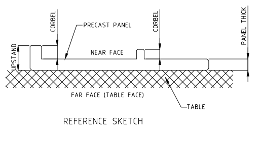
Upstand:
Upstand is typically used for return legs in a precast element (Panel, Column, Spandrel). Generally, upstand preferred near face in shop drawing. If any special requirement (architectural design) only goes for Far face.
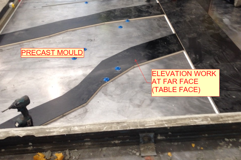
Because far face is a table face, so we can’t provide upstand on Far face due to manufacturing difficulties.
Corbel: Corbel is typically used for panel thickening increases in a precast element. Its also preferred near face in shop drawing.
Thickness for Upstand:
Total length of return value (sum of panel thickness) to be considered as upstand thickness.
Thickness for Corbel:
Thickness increase value (Apart from panel thickness) to be considered as corbel thickness.
Advantages:
1. The upstand and corbel profile formation used to avoid small size precast elements manufacturing.
2.And also it will help to avoid some small part of in-situ elements on site.
3. The construction time will be reduced.
4. The cost of manufacturing also will be reduced.
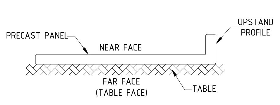
Near face (NF): Near face is a front view of the precast wall.
Far Face (FF): Far face is an outside view or trowel face or table face of the precast wall.
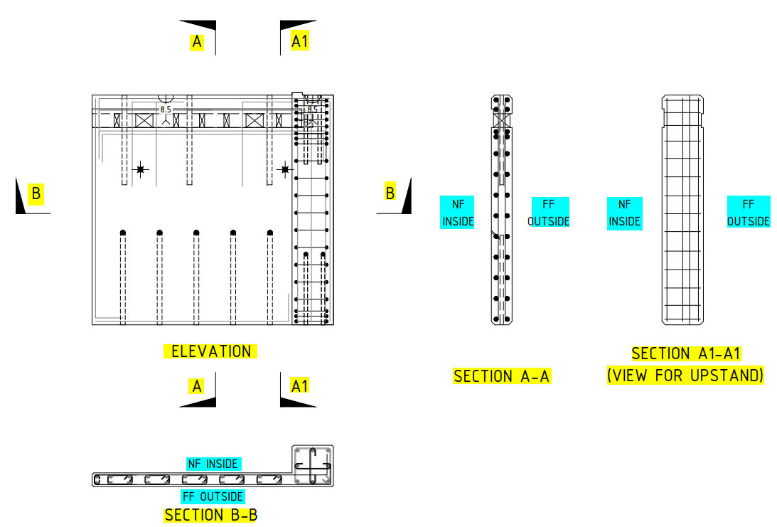
Near face and Far face indication playing a major role on shop drawings to identify the component placing for factory people while manufacturing panel. (Refer Fig.02)
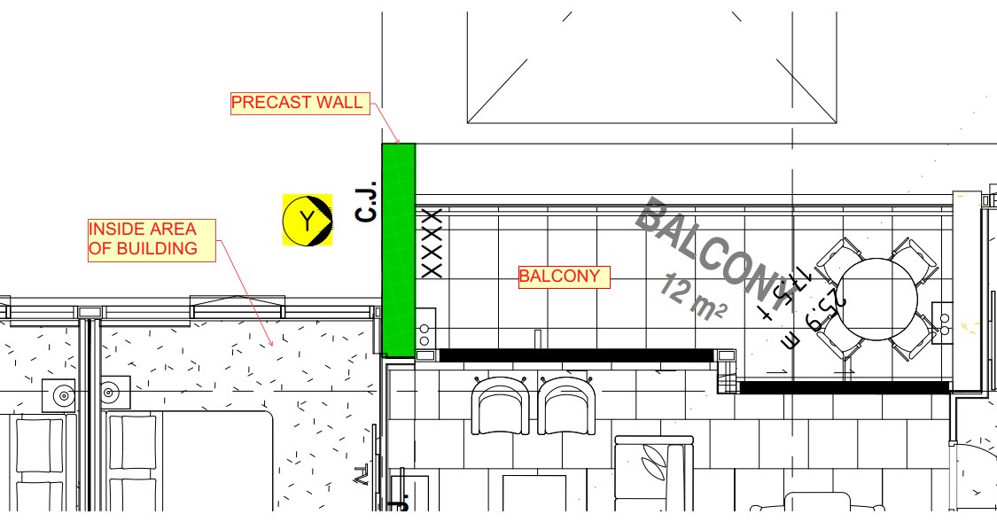
At initial stage we draw the panel footprint on marking plan and fix the panel view based on where the panel comes like inside or outside of the building.
In marking plan, we viewing the panels both inside and outside of the building because to achieve architect and structural aspects or requirements and to avoid some manufacturing difficulties.
The below mentioned details are used to fix the views for precast panels from marking plan.1. To View from inside of the building:
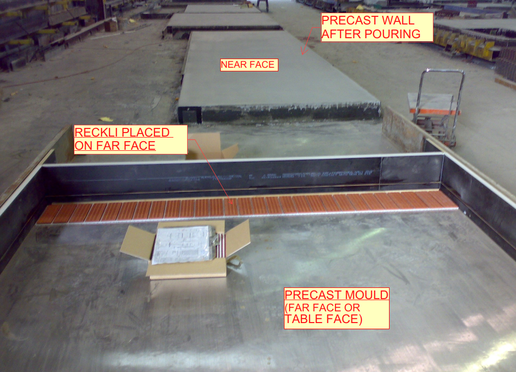
Good table finish will be on Far face.
Grooves, patterns, different profile design comes at outside of the building, so it will easy to assign profiles on far face of the panel and it will be on table face on factory. (Refer Fig.03 & 05)
For upstand or corbel to be comes at near face of the precast panels to avoid manufacturing difficulties.
If any bars connecting to in-situ at near face, we also view the panel from inside.2. To View from outside of the building:
For basement level panels no need trowel finish or good table finish on far face of the panel (Outside of the building). In this case we looking the panels from outside of the panel.
If panel have upstand or corbel profiles at outside of the buildings, we need to view the panel from outside to avoid manufacturing difficulties on factory. (Refer Fig.01)
In few cases, building inside is fully balcony and outside side is partially inside of the building. So, this kind of scenario we viewing the panel from outside of the building due to panel finish. (Refer Fig.04)
General:
For multi-storied buildings, we follow the same elevation number for same set-out from lower level to above levels.
The starting level of panels we will fix viewing direction as per current level architectural and structural aspects.
Some cases the lower-level panels come at inside of the building and above level panels comes at outside of the building. In this case we viewing the panels same as per lower levels but we flipped the above level panels for manufacturing purpose.
Advantages:
Drawing study is easy for factory people.
It will reduce the time delay of manufacturing the panels.
It will also avoid the manufacturing difficulties and Errors.
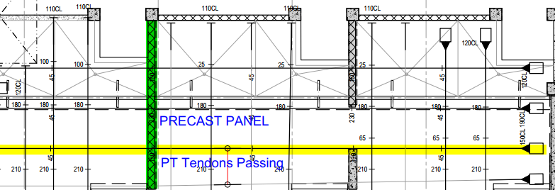
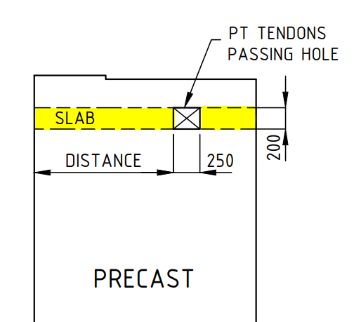
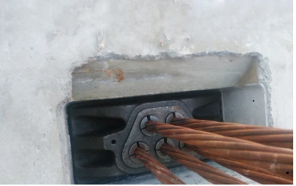
Subject: Things to do when we have post-tensioning cables passing through precast panels
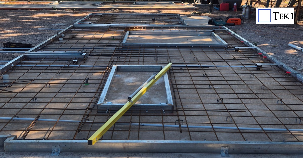
If we have both post-tensioning slabs in the location of precast, we have to provide a block-out hole in the precast to pass the tendons through the precast.
What we care to take when detailing precast panel.
We have to provide an opening in the panel for PT cables to pass through. Do not place any precast hardware closer than 100 mm from the hole/block-out.
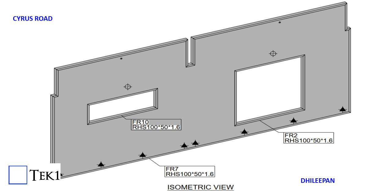
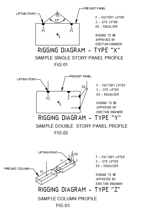
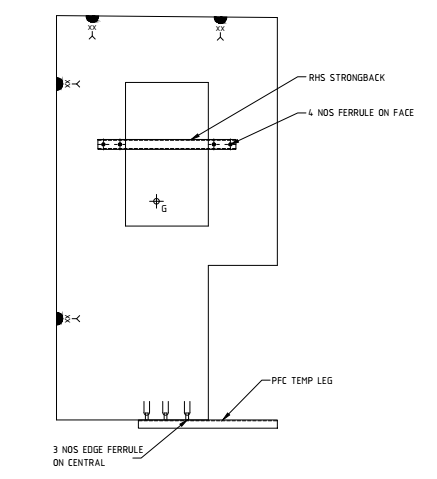
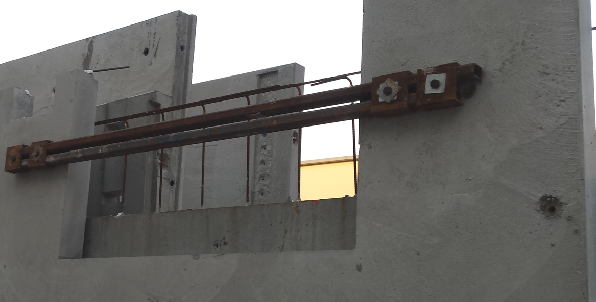
Normally we are using the strongback in window, Door opening, uneven profile and panel handling purpose. It’s used to avoid the panel breakup, crack and damage during the panel lifting from table, Transportation (Loading & Unloading) and Panel erection on site. We are using three types strongback based on the required strength.
1. PFC Strong back.
First is the PFC member which can be bolted to the face or welded to plates on edge.
2. RHS (Right hand side) Strongback.
Second is the New and preferred RHS which is bolted to the panel face.
3. Elbow Strongback.
Third is the Elbow strongback which is bolted to the panel face and hangs over one edge.
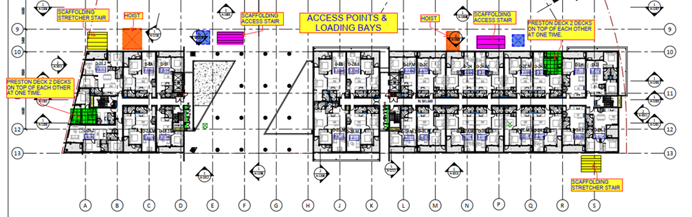
Every multi story buildings typically need the loading bay or hoist for each and every level during construction. A loading bay or loading dock is an area of a building where goods are loaded and unloaded to it from vehicle or site. On hoist or loading area of façade walls is being unbuilt up to end of construction. Final stage of construction only it needs to be built. Refer below picture for different types of loading bays are highlighted.
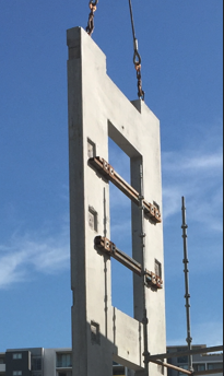
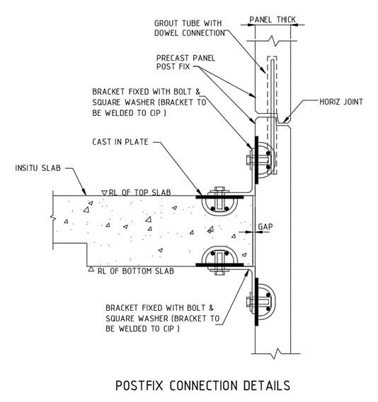
If the rest of the building is constructed by the precast, the hoist area also needs to be covered or fixed by precast panel. This type of covering panels are named post fix panel. Which means the panel will fix on the existing structure after completion of required task.
These post fix panels have different type of erection procedure, connection details compared to the all-other precast panels.
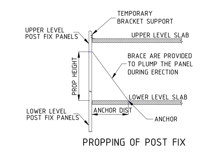
Propping Method for Post Fix Precast:
The temporary bracket connection between panel and to the slab need to be done at the top of the panel. The rest of the panel hanging below slab where braces are connected to plumb the panel as well as support. That the brace is anchored below level slab. The bottom of post fix panels is connected with dowel & grout tube arrangement to the below level precast panel. Refer the propping snap.
Permanent Connection of post fix panel:
The grout tube with dowel connection between the panels are only resist the horizontal movement, the additional permanent connection is made between panel and the slab through cast in plate and weld on site at both top and bottom the slab. The structural connections details are need structural engineer approvals. Refer below picture for typical connection details.
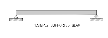
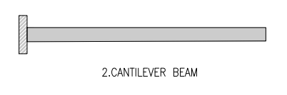
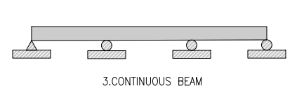
According to the types of supports provided for the beams, they are classified as:
1. Simply supported beam.
2. Cantilever beam.
3. Continuous beam.
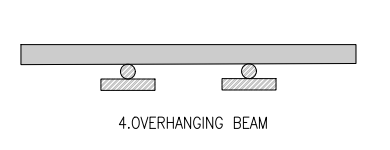
4. Overhanging beam.
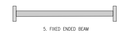
5. Fixed beam.
SIMPLY SUPPOETED BEAM: This type of beam is supported at both ends consisting of pin support at one of the ends and roller support at the other end.
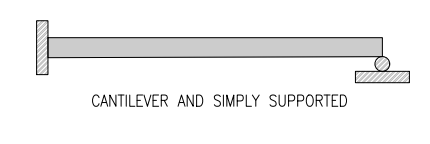
CANTILEVER BEAM: A beam with one end free and the other end is fixed is called Cantilever.
CONTINUOUS BEAM:
A beam which is supported on more than two supports is called a continuous beam.
OVERHANGING BEAM: Overhanging beam is the combination of cantilever and a simply supported beam. This type of beam in which the end portion of the beam extends more from the support. It’s divided in to two types.
A) Single overhanging beam (This type of beam is extended beyond the support at one end only)
B) Double overhanging beam. (This is of beam is extended beyond the support at both ends)
FIXED BEAM: This type of beam is fixed at both ends it called fixed beam.