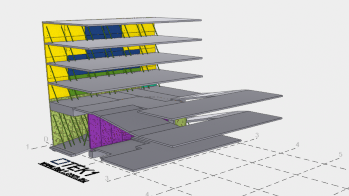
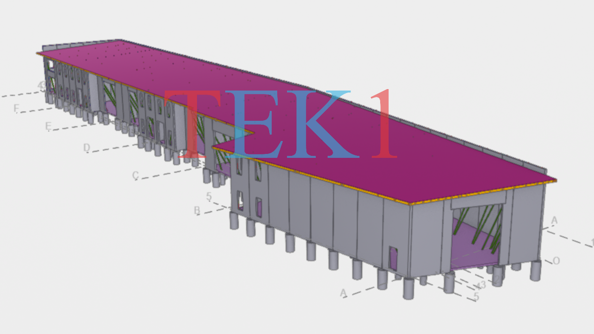
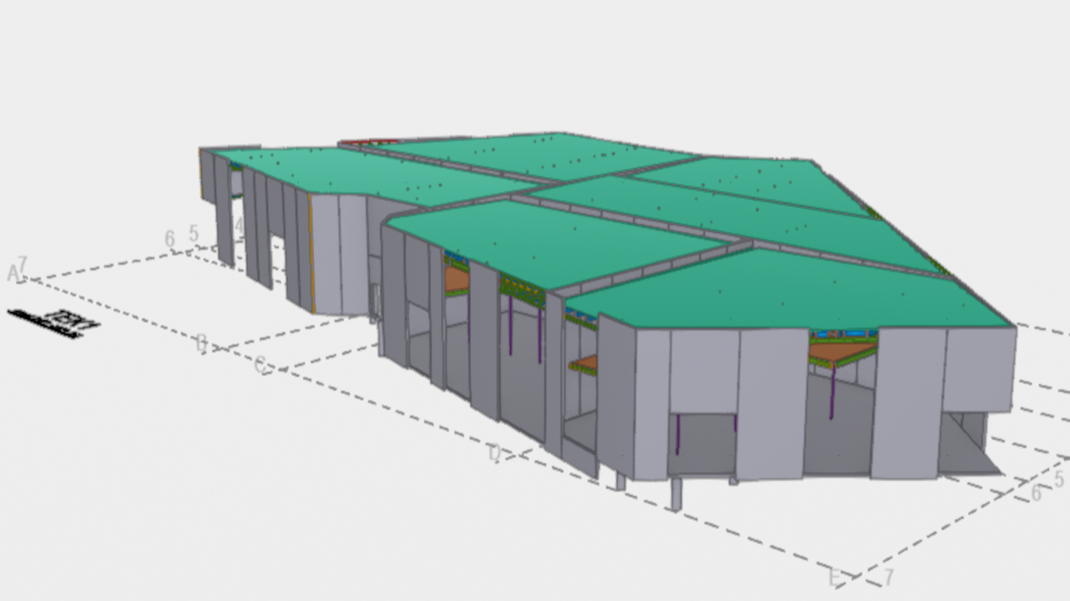
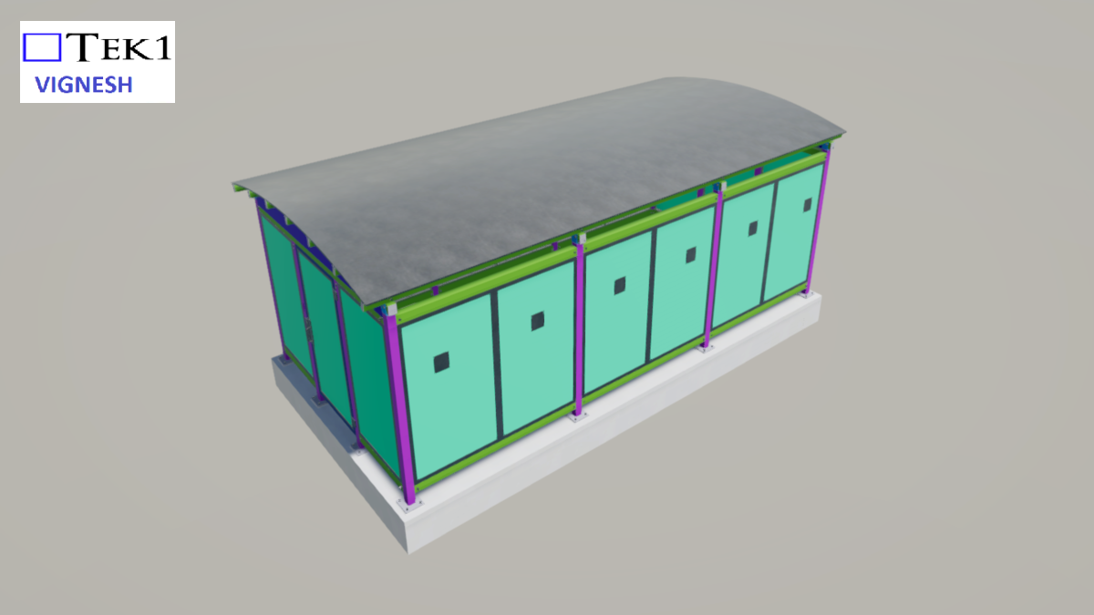
Another example of precast panel shop drawings. Drafted with expertise. With nearly 20 years of experience and active capture of good and bad things about precast, you can count on Tek1 to deliver flawless shop drawings for your next project
Another example of precast panel shop drawings. Drafted with expertise. With nearly 20 years of experience and active capture of good and bad things about precast, you can count on Tek1 to deliver flawless shop drawings for your next project
Another example of precast panel shop drawings. Drafted with expertise. With nearly 20 years of experience and active capture of good and bad things about precast, you can count on Tek1 to deliver flawless shop drawings for your next project
This is an example where we have model shared with client for completing the precast panels and structural steel.
Clients save time and in turn money when both precast and structural steel is detailed in one single model. Co Ordination is easier.
With nearly 19 years of experience detailing structural steel and precast panels, Tek1 has the expertise to deal with any type of precast strucutures in Australia
This is an example where we have model shared with client for completing the precast panels and structural steel.
Clients save time and in turn money when both precast and structural steel is detailed in one single model. Co Ordination is easier.
With nearly 19 years of experience detailing structural steel and precast panels, Tek1 has the expertise to deal with any type of precast strucutures in Australia
This is an example where we have model shared with client for completing the precast panels and structural steel.
Clients save time and in turn money when both precast and structural steel is detailed in one single model. Co Ordination is easier.
With nearly 19 years of experience detailing structural steel and precast panels, Tek1 has the expertise to deal with any type of precast strucutures in Australia
When there is precast panels and structural steel to be detailed, why go approach two separate detailers. Keeping everying in one model saves money and time. Tek1 has been detailing structural steel and precast panels for 20 years now. With large expert team, no job is difficult for us
When there is precast panels and structural steel to be detailed, why go approach two separate detailers. Keeping everying in one model saves money and time. Tek1 has been detailing structural steel and precast panels for 20 years now. With large expert team, no job is difficult for us
When there is precast panels and structural steel to be detailed, why go approach two separate detailers. Keeping everying in one model saves money and time. Tek1 has been detailing structural steel and precast panels for 20 years now. With large expert team, no job is difficult for us
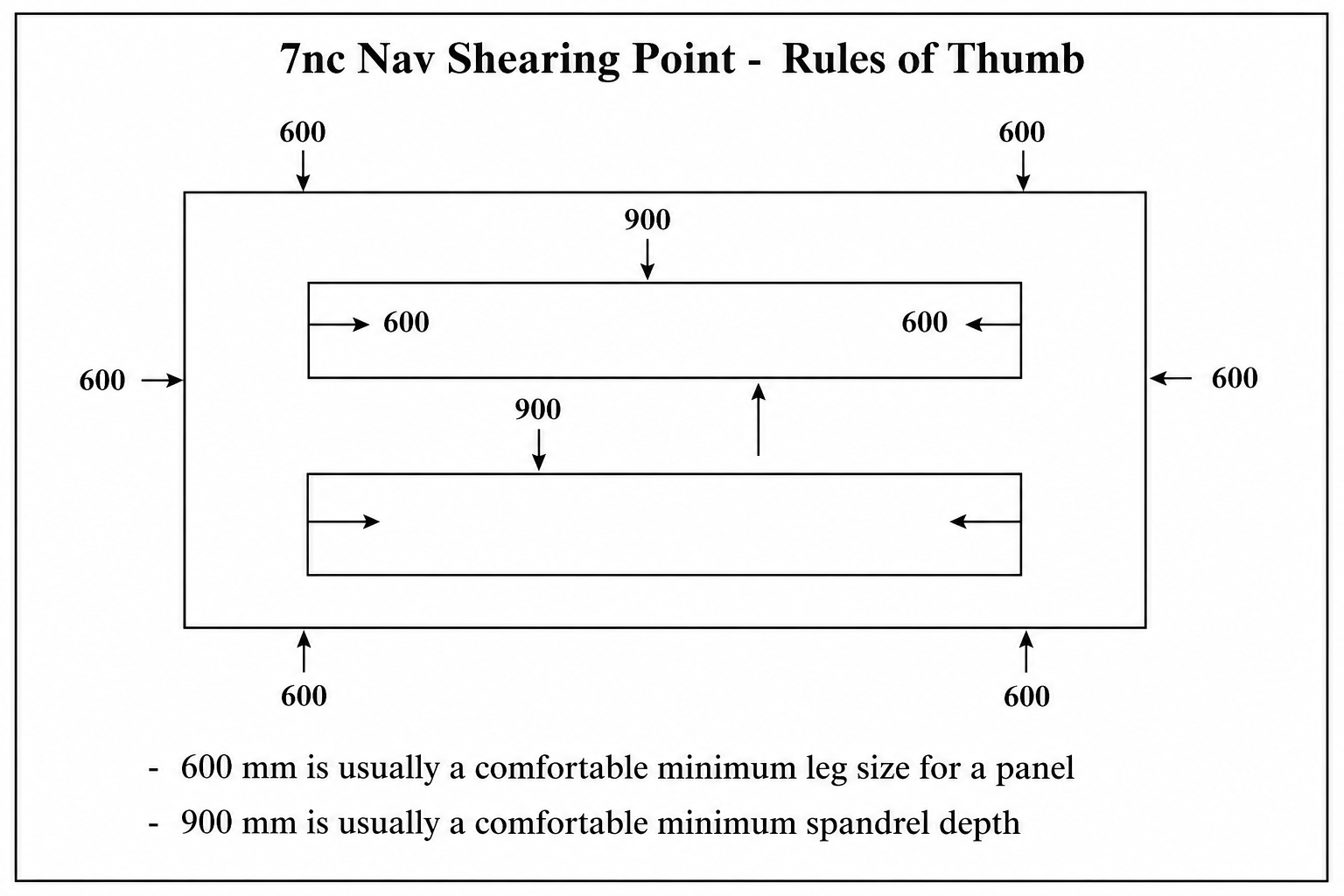
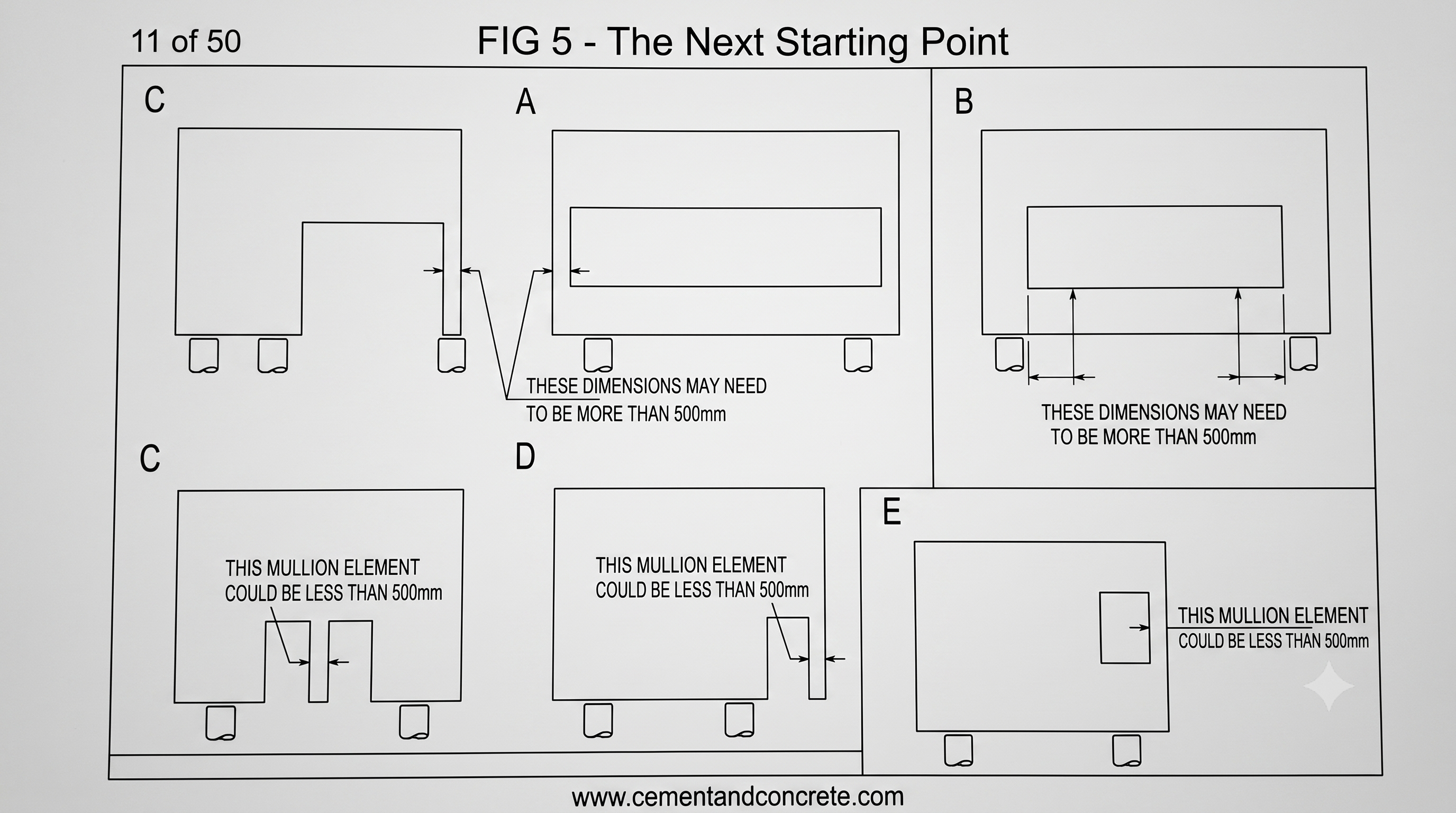
Given below si minimum recommended sizes for Precast Panel legs and spandrels. However if the sizes are smaller the detailer will have query with the engineer.
if you wish to learn more about steel detailing, and Tekla. Video by Ben Koshy.
For more details about my work. If you’re interested in Tek1 to do your steel detailing, please email: [email protected] with details about your project and a description of your goals / objective.
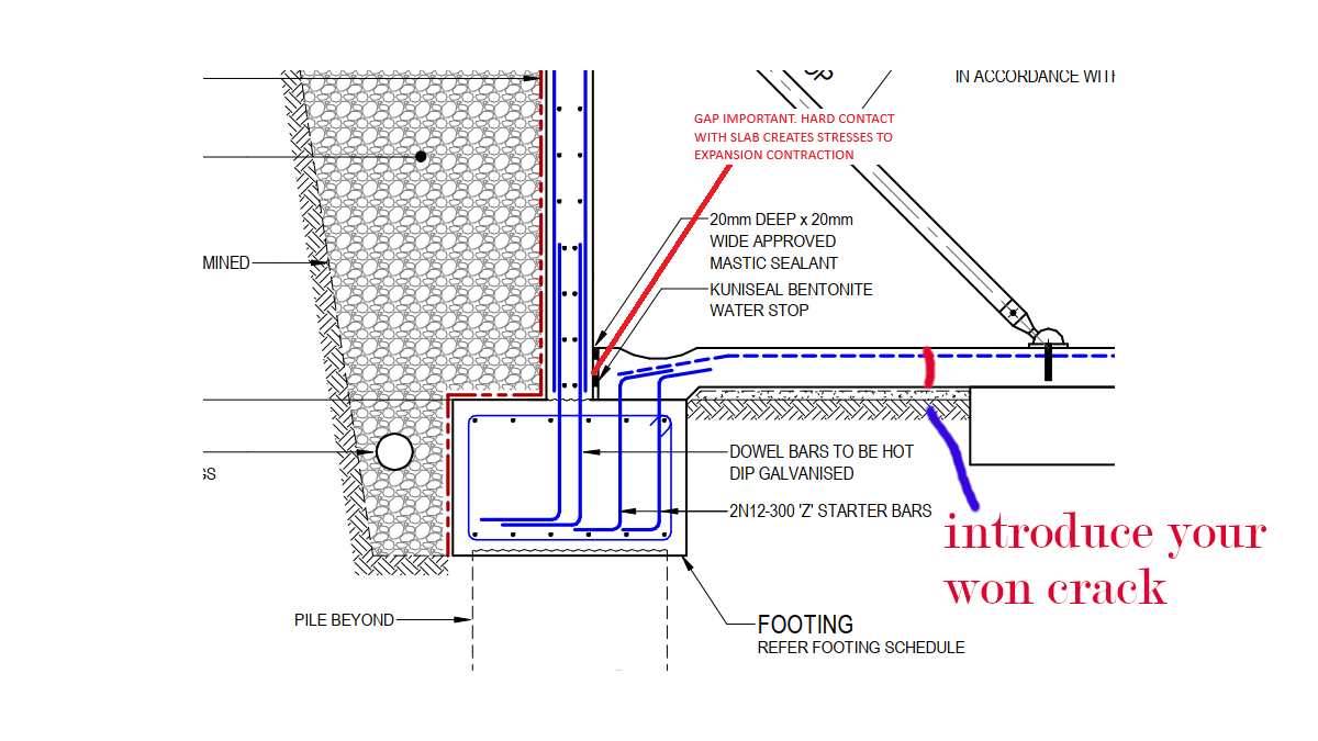
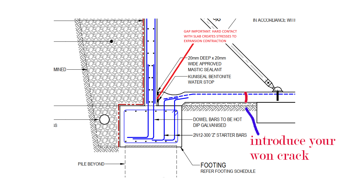
Load bearing precast element is anything that receives load from a precast or structural members and transfers the load to another structural member or precast. These precast elements can also be used along as façade, boundary walls, or for architectural design purposes.
What is non-load bearing precast element?
Non-load bearing precast element is anything that may receive load but must not transfer loads to any other structural members or precast. Normally these kind of walls are used only for partition, façade, boundary walls, or for architectural design purposes
What is Partially-load bearing precast element?
Partially-load bearing precast element is anything that receives load from a precast or structural members and transfers the load to another structural member or precast. But only a portion of precast receives and transfers load and the remaining portions will act as non-load bearing ones. (Single precast element which acts both as load bearing & non-load bearing)
Data’s, panel types & other details for
Load-bearing element
Non-bearing element
Partially-load bearing element
Grade, can be higher upto 80MPa
Grade enough be 40MPa (UNO)
Grade, can be higher up to 80MPa
Gap between two elements are filled with grouting material of required grade
Gap between two elements are filled with Soft joint caulking only. no grouting.
Gap between two elements are filled with grouting material of required grade, extent of filling is for load bearing portion. Remaining portion will be soft joint caulking only
Dowels to be black finish (UNO)
Dowels to be Galvanized finish
Dowels to be Black or Galvanized finish, as per load bearing extend (UNO)
Dowel length, size & spacing as per Engineer’s requirement
Dowel length, size & spacing as minimum as possible after discussing with Manufacturer or Engineer
Dowel length, size & spacing as per Engineer’s requirement for LBP portion Dowel length, size & spacing as minimum as possible for NLBP portion
Dowel & Grouting materials will transfer load to adjoining element
Dowel will be used to position the precast element & no grouting material present to transfer load. So loads will not be transferred.
Combination of LB & NLB criteria
No ring seal around the dowel
High density foam ring seal around the dowel
No ring seal around the black dowel High density foam ring seal around the Galvanized dowel
Grouting material will cover the dowel, so oxidation in dowel is negligible
No Grouting material, oxidation in dowel is possible. So high density foam ring seal is used and dowels are galvanized to prevent oxidation in dowel
Combination of LB & NLB criteria
No additional tubes or caps needed
Plastic tube will be placed over upper half of dowel. Compressible cap will be placed over the top of the dowel bar.
Combination of LB & NLB criteria
Connection with slab must
Connection with slab may not needed with respect to engineer requirement