Category: Projects

  • THE USAGE OF NEAR FACE(NF) AND FAR FACE(FF) INDICATION ON SHOP DRAWINGS

    Near face (NF): Near face is a front view of the precast wall.

    Far Face (FF): Far face is an outside view or trowel face or table face of the precast wall.

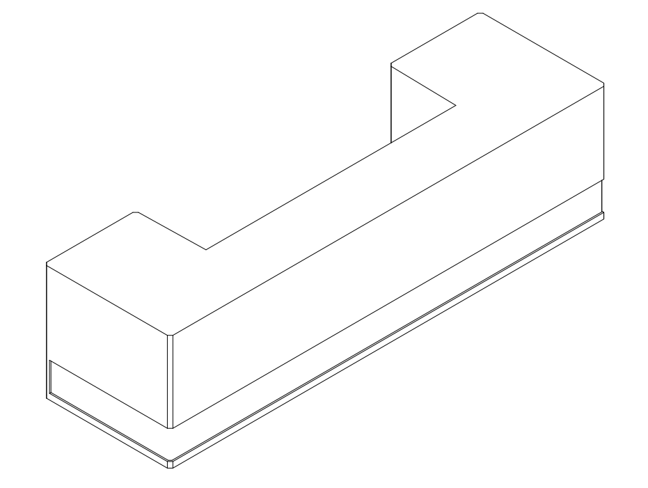
    • Near face and Far face indication playing a major role on shop drawings to identify the component placing for factory people while manufacturing panel. (Refer Fig.02)
    • At initial stage we draw the panel footprint on marking plan and fix the panel view based on where the panel comes like inside or outside of the building.
    • In marking plan, we viewing the panels both inside and outside of the building because to achieve architect and structural aspects or requirements and to avoid some manufacturing difficulties.
    • The below mentioned details are used to fix the views for precast panels from marking plan.1. To View from inside of the building:
    • Good table finish will be on Far face.
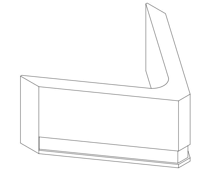
    • Grooves, patterns, different profile design comes at outside of the building, so it will easy to assign profiles on far face of the panel and it will be on table face on factory. (Refer Fig.03 & 05)
    • For upstand or corbel to be comes at near face of the precast panels to avoid manufacturing difficulties.
    • If any bars connecting to in-situ at near face, we also view the panel from inside.2. To View from outside of the building:
    • For basement level panels no need trowel finish or good table finish on far face of the panel (Outside of the building). In this case we looking the panels from outside of the panel.
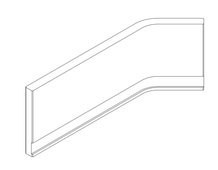
    • If panel have upstand or corbel profiles at outside of the buildings, we need to view the panel from outside to avoid manufacturing difficulties on factory. (Refer Fig.01)
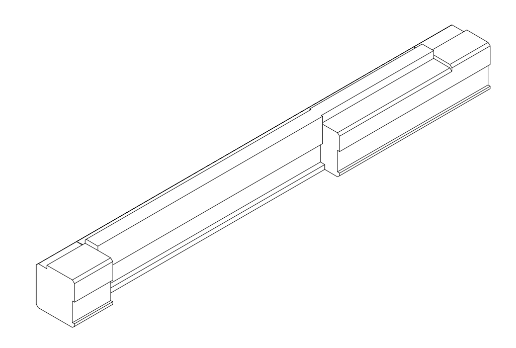
    • In few cases, building inside is fully balcony and outside side is partially inside of the building. So, this kind of scenario we viewing the panel from outside of the building due to panel finish. (Refer Fig.04)

    General:

    • For multi-storied buildings, we follow the same elevation number for same set-out from lower level to above levels.
    • The starting level of panels we will fix viewing direction as per current level architectural and structural aspects.
    • Some cases the lower-level panels come at inside of the building and above level panels comes at outside of the building. In this case we viewing the panels same as per lower levels but we flipped the above level panels for manufacturing purpose.

    Advantages:

    • Drawing study is easy for factory people.
    • It will reduce the time delay of manufacturing the panels.
    • It will also avoid the manufacturing difficulties and Errors.
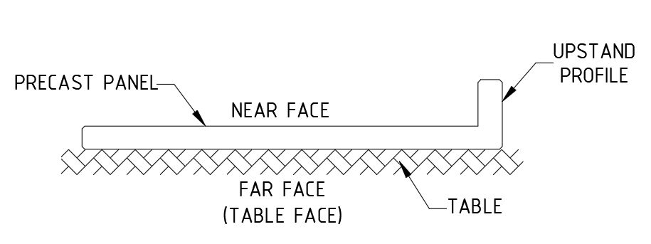
    Fig.01
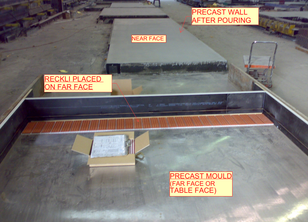
    Fig.02
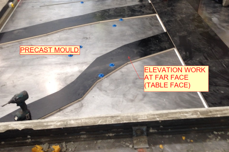
    Fig.03
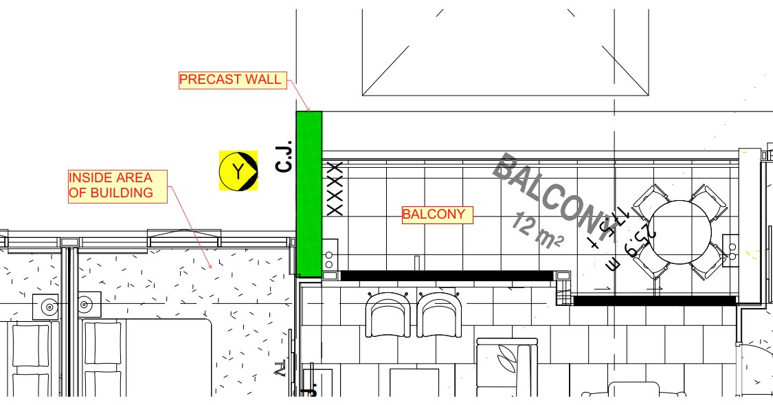
    Fig.04
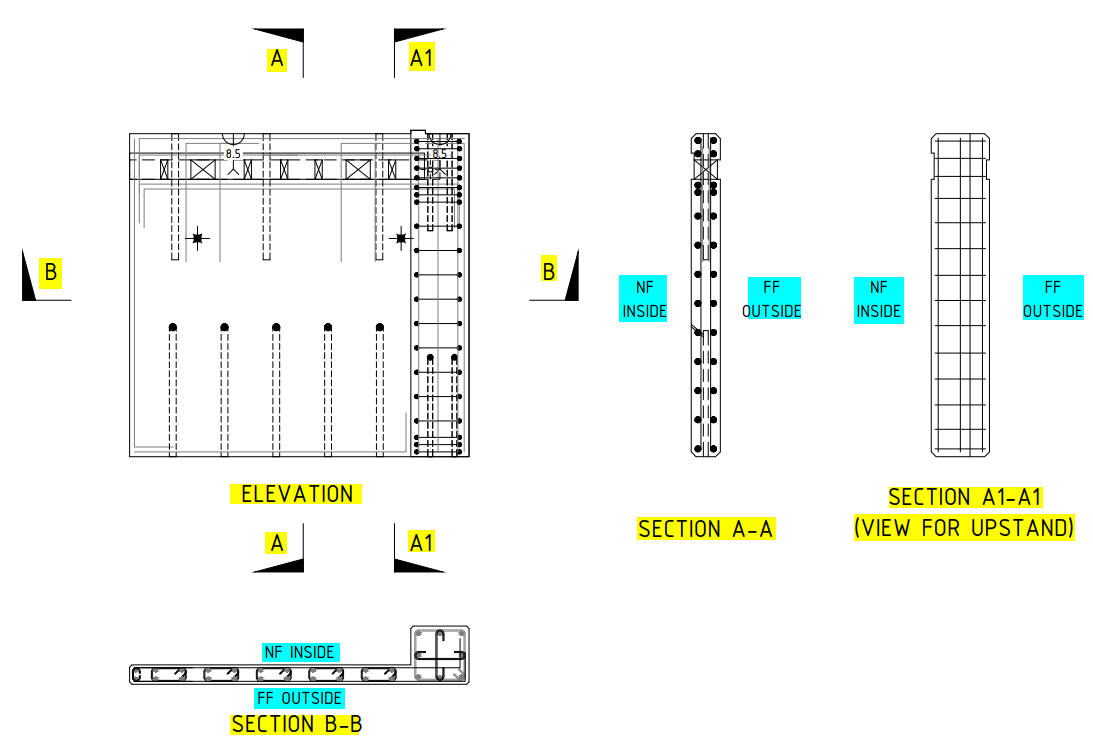
    Fig.05
  • RIGGING DIAGRAM AND IT’S USES

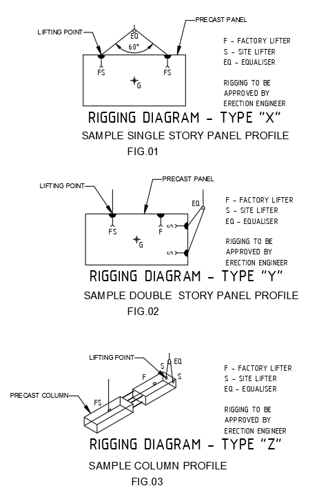
    • The rigging detailed diagrams are shown on shop drawings. (Ref Fig.01,02 & 03)
    • The rigging diagrams are designed based on the precast panel profiles.
    • It is indicating the lifting point position of precast panels for both factory and site.
    • Erection engineer will be approved the rigging diagram details.
    • The site people are preplanning to lifting the precast panels for erection.
    • It is indicating the demolding lifting points. So, the factory people will aware while lifting the panels on factory.
    • It is designed to distribute loads equally between all anchors in precast components such as walls, beams or flat slabs and etc.
    • It is also used for loading and unloading the panel while transportation.
    • The lifting accessories may be in the form of cables, hooks and etc.
    • Many accidents and failures will be avoided with the help of rigging diagram.
    • The time delay of the lifting to be reduced.

    (SAMPLE RIGGING DIAGRAMS FOR REFERENCE)

  • Drawings to be used to draw Precast Panels

    Architectural Drawing

    1. Concrete layout drawing
    • describes the location and layout of the precast
    1. General arrangement drawing
    • describes the building’s space arrangement, such as rooms, bathrooms, and so on.
    1. Window Plan and Elevations
    • describes the size and location of the windows and doors.
    1. Arch elevation and its sectional elevations
    • describes the architectural finishes and presentations on the exterior and interior.
    1. Stair plan & elevation drawings
    • describes the details of the stairs, steps, and landing.
    1. Core wall plan and elevations
    • describes the lift shaft drawings and their specifics.

    Structural drawings

    1. Column schedules & details
    • describes the column size and its reinforcement details.
    1. Core wall plan and elevation details
    • describes the details of the lift/stair wall reinforcement.
    1. Typical Precast Details
    • describes the general reinforcement and its details.
    1. Typical stair details
    • describes the stair landing slab and steps, as well as the reinforcing details.
    1. Slab profile plan and sectional details
    • describes the thickness of the slab, the beam, and the reinforcement details (up and down).
    1. Ramp plan, section, and elevation details
    • The Ramp Angle, Reinforcement, and Thick Sails are all described.
    1. Precast elevations & sectional details
    • describes the reinforcement, grade of concrete, and additional reinforcement details.  

    Service drawings

    1. Crane details
    • describes the loading area and crane weights at various lifting points.
    1. Hydraulic drawings
    • describes the drain or overflow opening and its details, among other things.
    1. Mechanical Penetration Details
    • describes the AC duct opening, etc.
    1. Post-tensioning slab details
    • describes the PT tendon passing areas and their specifics.
    1. Lift shaft drawing
    • describes the lift shaft opening, the controller box, and its details.
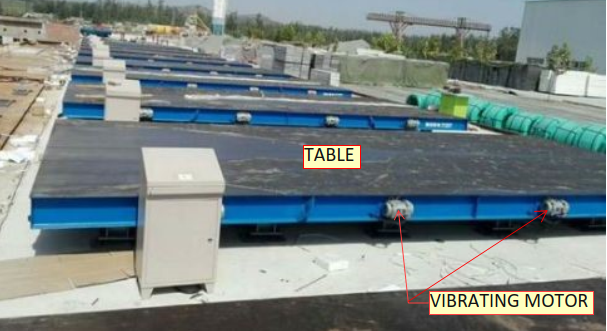
  • VIBRATING TABLE FOR PRECAST FABRICATION

    • Vibrating table using for compacting and consolidating the stiff and harsh mixes in precast structures on factory or yards.
    • While using this vibrator the concrete will be spreads equally at all corners of the precast structure in mold.
    • It will help to improve the strength and quality of precast concrete structure.
    • The void or bubble formation will be avoided.
    • So, the cracks formation also to be reduced.
    • It will reduce the man power.
    • The fabrication time is less.

    Fig.01 (Vibrating table)

  • VARIOUS SPANDREL PROFILES

    • Spandrel profiles are designed based on architectural aspects on Elevation purpose.
    • When doing this kind of profiles, it’s challenging and more interesting to achieve.
    • And also, it will help to improve our drawing knowledge and skill.
    • We handled and come across different types of precast spandrel profiles as per below,
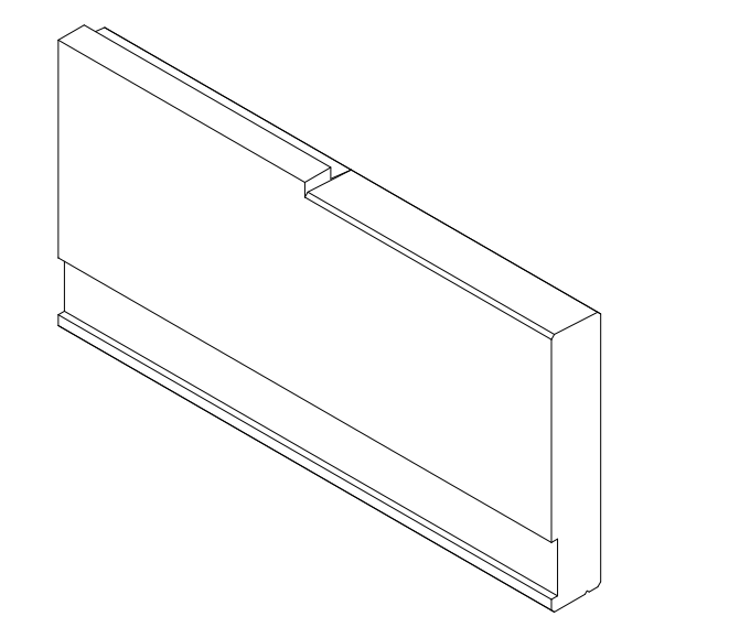
    1. Spandrel with straight profile
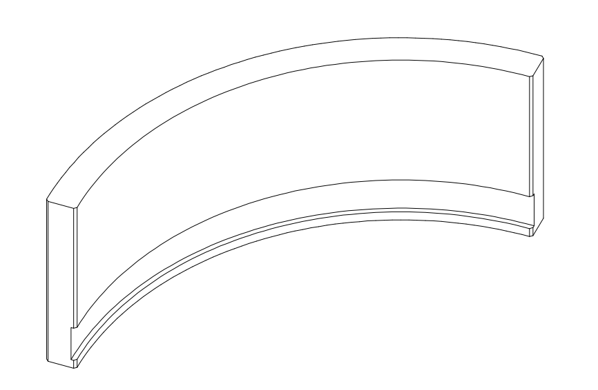
    2. Spandrel with curve profile
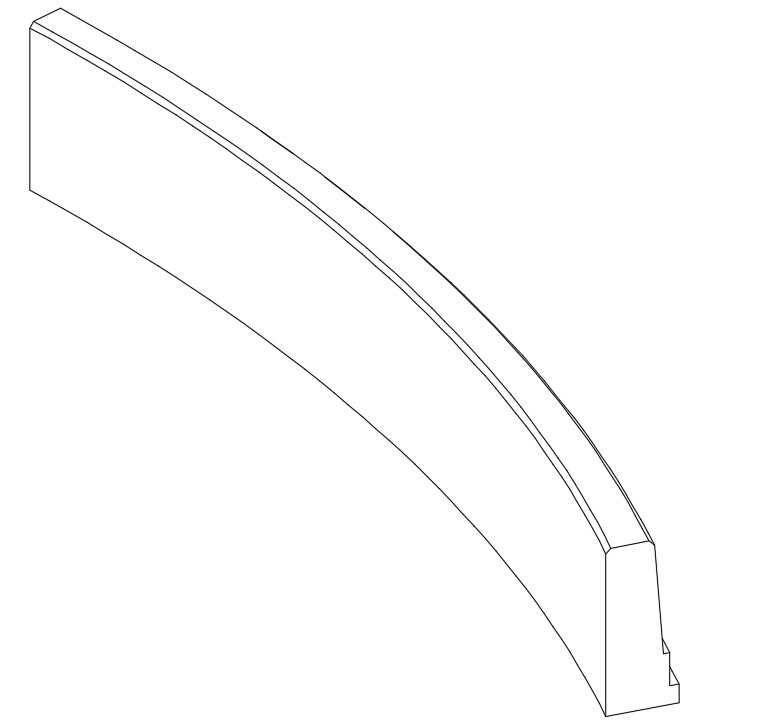
    3. Spandrel with curve & triangle profile
    4. Spandrel with L shaped profile
    5. Spandrel with U shaped profile
    6. Spandrel with V shaped profile
    7. Beam type spandrel1. Spandrel with straight profile (Ref. Fig.01)

    Fig.01

    2. Spandrel with curve profile (Ref. Fig.02)

    Fig.02

    3. Spandrel with curve & triangle profile (Ref. Fig.03)


    Fig.03

    4. Spandrel with L shaped profile (Ref. Fig.04)

    Fig.04

    5. Spandrel with U shaped profile (Ref. Fig.05)

    Fig.05

    6. Spandrel with V shaped profile (Ref. Fig.06)

    Fig.06

    7. Beam type spandrel (Ref. Fig.07)

    Fig.07

  • TYPES OF CRANES FOR PRECAST BUILDING CONSTRUCTION

    About Crane:

    Cranes are used for loading and unloading the precast walls on yard or site. Each precast walls or components are usually large and heavy weight, so cranes are required to lift them. And also, cranes are easily done when set the precast position while erecting on site. It will help to reduce manpower and cost of precast wall lifting and also to reduce construction time delay.

    We mainly used two types of cranes on both factory and site.

    1. Tower crane (Ref. Fig 01)
    2. Mobile crane (Ref. Fig 02)

      1. Tower Crane:
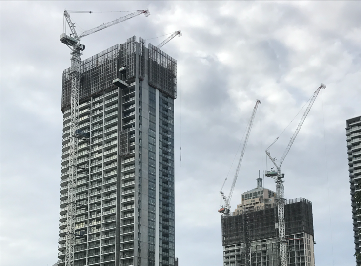
    • For precast construction the tower cranes are playing major role to handle precast walls in the yard and also during erection on site.
    • It’s mainly used for multi storied building construction.
    • Tower cranes are inbuilt on site. So, safety, selection, placement, and reliability of tower cranes are very important to completion of Precast buildings on time.
    • It is proven to be safe, long lasting and very fast in construction
    • The big issue is wind acting on the tower crane. The small collision may lead to big accidents or damage the precast elements and also delay in completion of job. So, while fixing the tower crane we need to fix in proper placement to avoid unwanted damages and waste of cost.
    • Tower cranes are fixed on site so it can’t be moved to one place to another.
    • Tower crane is used to multi-levels building’s to lifting the panels from ground floor to needed level. But it has limitations to cover wide area.


    Fig.01

    2. Mobile crane:

    • Mobile cranes can be used to lift, carry, and place materials in many applications.
    • For tilt-up construction jobs can be completed quickly, accurately, and safely.
    • Sometimes mobile cranes are help for tower cranes to rotate and move the precast walls from truck or site.
    • It will also help for loading and unloading the precast walls from the truck.
    • The wind energy will not affect while lifting precast walls when compared to tower cranes.
    • Mobile cranes are movable. So, if we need to move any other places it is easy.
    • And it’s used for mainly single-story building construction.
    • It is compact in size so it’s can’t occupy more place on site.
    • Compare to tower crane we can’t use this crane for multi-levels building. But it’s used to cover the wide range of area on site.

    Fig.02

  • PURPOSE OF SPANDREL OVER ON MARKING PLAN

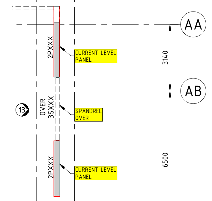
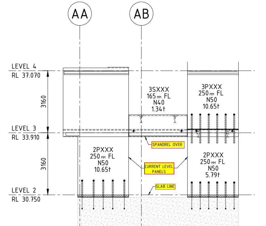
    • When preparing marking plans, we need to show all spandrels set-outs on the plan layout that are fixing into the slab over. (Refer Fig.01 & 02)
    • It will help to find out which spandrel comes at level above.
    • While scheduling the current level panels, mean time it will helps to scheduling the above level spandrels.
    • And, it will help to manufacturing and erecting the spandrels with lower-level panels at same time.
    • For site crews, they also aware when pouring slab and erecting panel sequence without any time delay on site with reference marking plan.
    • It will reduce time consumption to plan for both manufacturing and erecting panels.
      Fig. 01 (Snap for Reference Marking Plan)


    Fig. 02 (Snap for Reference Elevation)

  • CONSIDERATION OF PRECAST LID SHOP DWGS

    The purpose of LID panel:

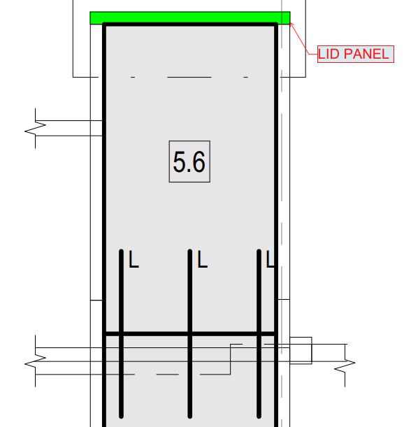
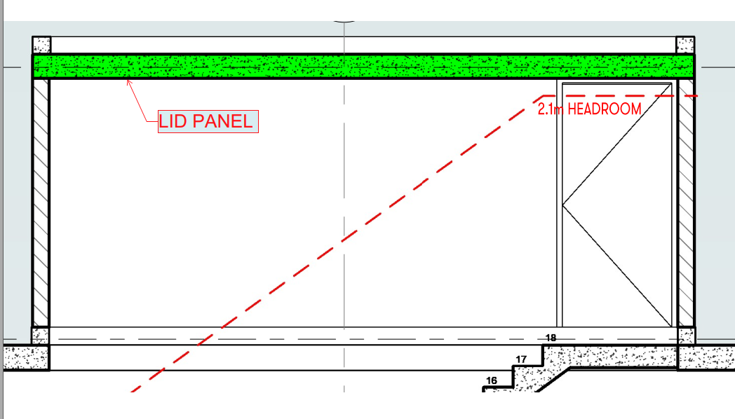
    LID panels are most commonly used for covering up the openings on building roof areas and also some inner part of the building where the precast slab is required. It can be seen in locations like lifts, stairs, water tanks, etc.

    LID PANEL ON LIFT

    LID PANEL ON STAIR

    Manufacturing consideration of LID panels:

    • Viewing direction of the lid panel is either plan view or view from below. Depending on consideration of manufacturing difficulties and near face finish and different profile requirements, it may change as vice-versa.
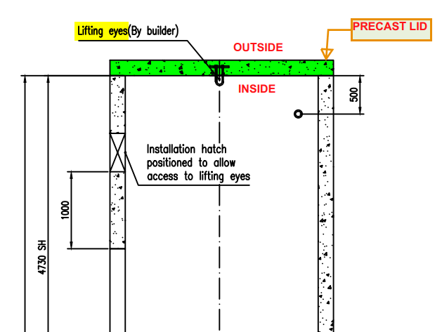
    • If lifting eye/ hook is projecting outside of lid means, we have to view the face with lifting eye as near face for manufacturing purposes. (Refer lifting hook/eye elevation view)
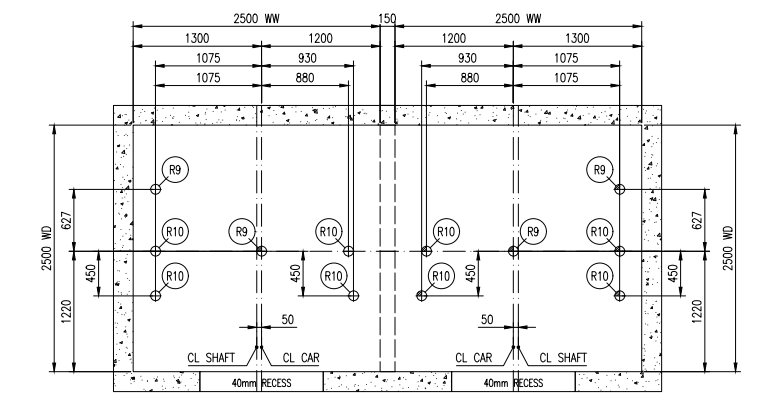
    • In lift lid, lifting hook/ lifting eye needs to be provided if it needs to be cast in the lid. Lifting hook detail normally given in lift drawing. (Refer lifting hook/eye placement plan view)
    • We can provide face lifters and either top or side lifters used for erection, lifting off table and transportation purposes.
    • Face lifters were used for installation of the lid on site. Whether its need to be near face or Far face is decided by viewing direction.
    • Bottom connection of lid most likely by grout tube to its lower panel or In-situ.

    LIFTING HOOK/EYE ELEVATION VIEW

    LIFTING HOOK/EYE PLACEMENT PLAN VIEw

  • Difference between Normal Table and Tilt up Table

    General Details about table:

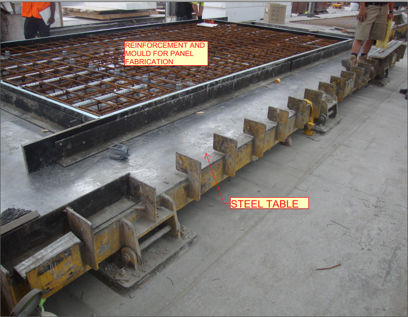
    • Tables are used for fabrication of precast panels in factories or yards with good quality, finish, curing and low time consumption.
    • Different types of materials used for tables like timber, aluminum and steel. But steel is mainly used for tables because it’s good for repetitions, gives good vibration to concrete, it’s not easily damaged and tables do not expand when it’s wet, etc.
    • The cleaning process is also easily done for steel tables with the help of air blowing or cotton waste.
    • In the yard there are different types of tables used for fabrication.
      For example normal fabrication tables and tilt up tables.

    Normal table:

    • Normal tables are mainly used to fabricate most of the precast panels.
      (Refer Fig 1)

    Fig 1

    • Advantages:
    • Normal tables will not take more manpower for cleaning and fabrication of precast panels.
    • The maintenance is easy
    • The cost is low when compared to other types of table.
    • It can easily fix where we need to fabricate the panels.
    • It will be fixed on the floor, so the visibility of the table is good for all.
    • Disadvantages:
    • It’s not suitable for doors or big opening panels. Because in case of lifting panels it may break.
    • Normal table needs additional lifting support.

    Tilt up table:

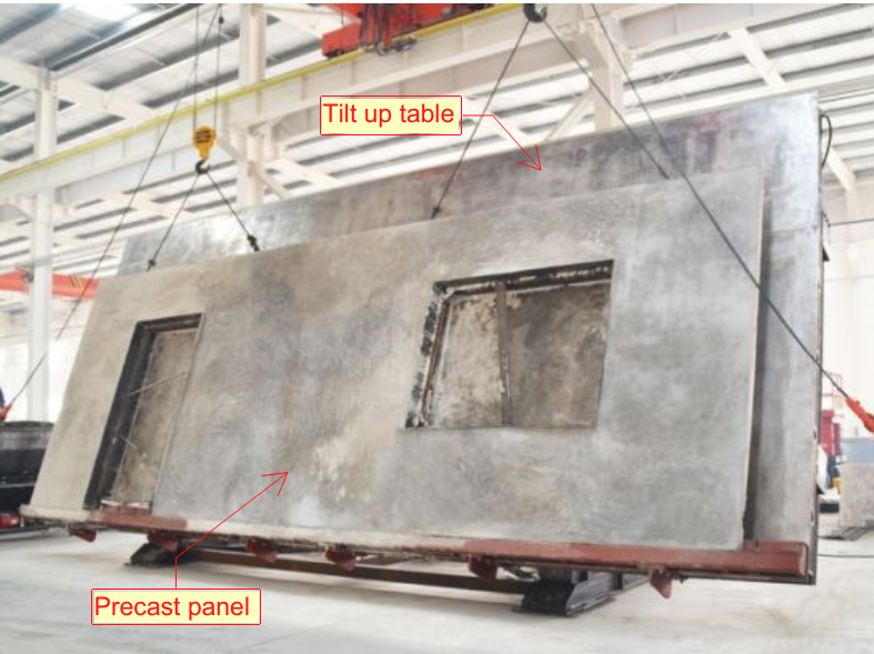
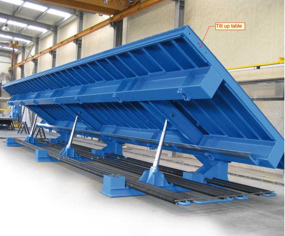
    • The tilt up tables are mainly used for Doors and big opening panels and also other types of panels. (Refer Fig 2 & 3)
    • The tilting process allows the precast concrete element to be removed safely and without damaging it.
    • The titling tables are designed in particular for mobile use and can be quickly transported from the yard.
      Fig 2


      Fig 3

    • Advantages:
    • This table is good for fabricating and lifting the door, opening type of panels.
    • Hydraulic Tilt up Tables reduce manufacturing time because it’s not require more pouring time to lift the panel from table.
    • Vibration technology based operation ensures qualitative compaction of concrete and a consistency in quality.
    • It’s very high level of concrete compacting with low noise.
    • Minimal costs when transporting the tilt up table.
    • Disadvantages:
    • Manpower is necessary and also needs knowledgeable people for handling.
    • The maintenance is difficult
    • The cost is high
    • It’s not movable, so we need to collect materials at a nearby table.