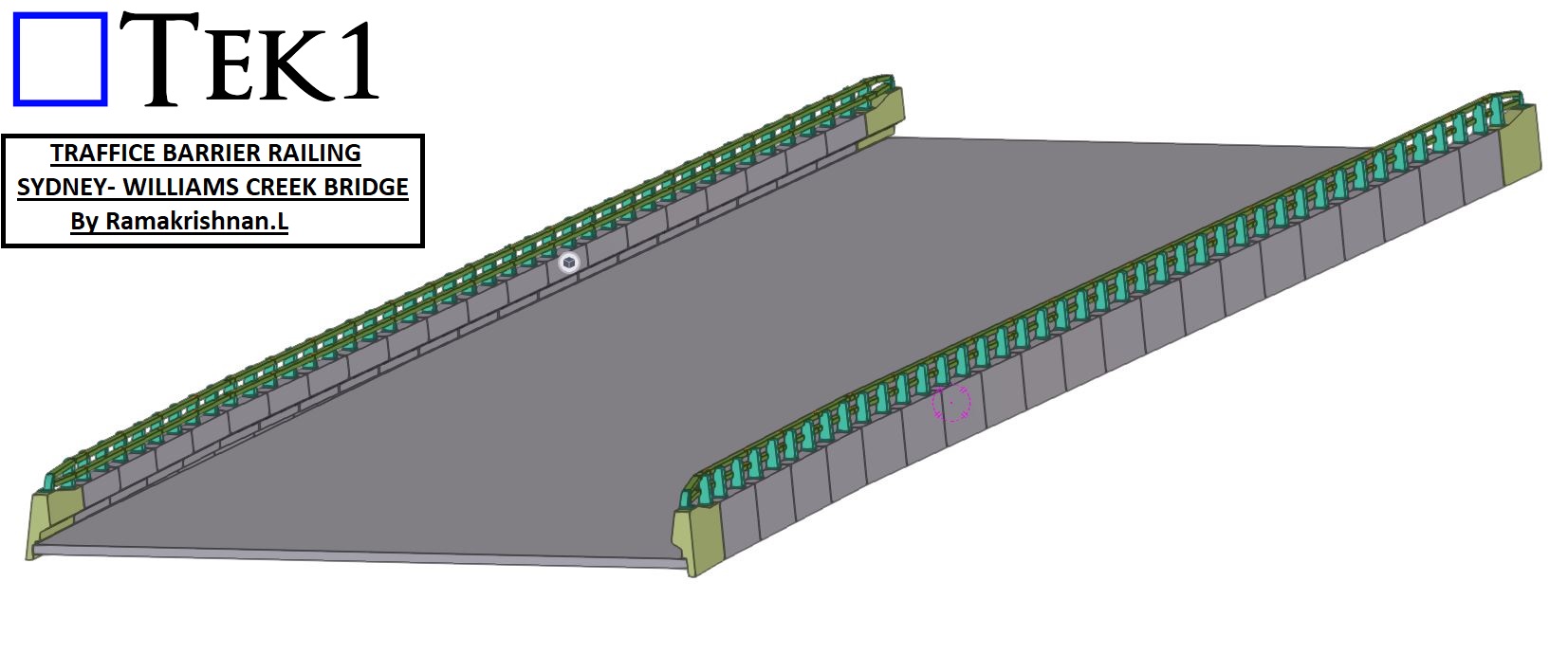
TEK1 recently completed the project TRAFFICE BARRIER RAILING project for the William Creek Bridge in Sydney. .
Project Overview
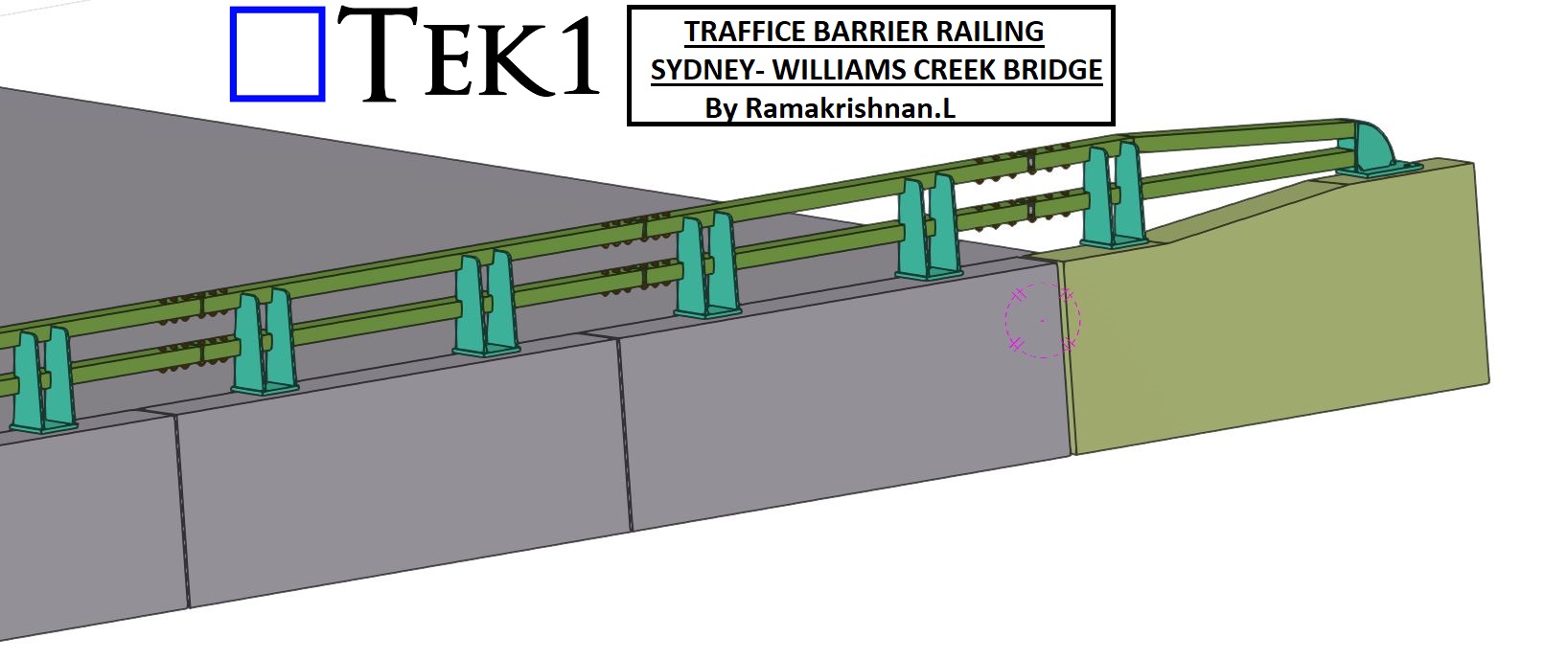
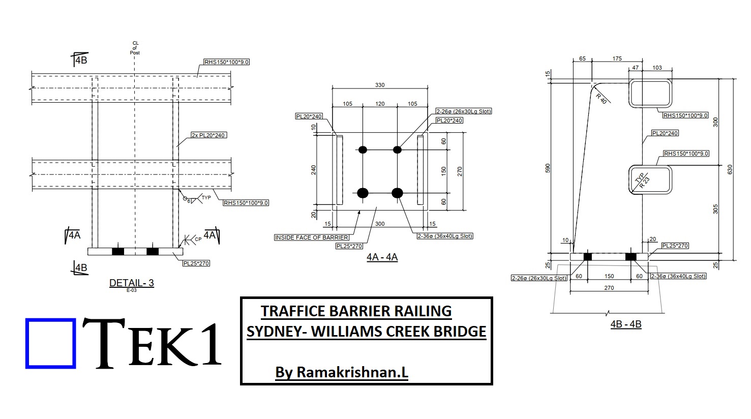
The primary focus of this project was the detailing and coordination of the barrier railing connections with respect to the precast barrier. These connections are integral to ensuring the railing system’s strength, stability, and compliance with safety standards.
Key Features of the Railing Connections
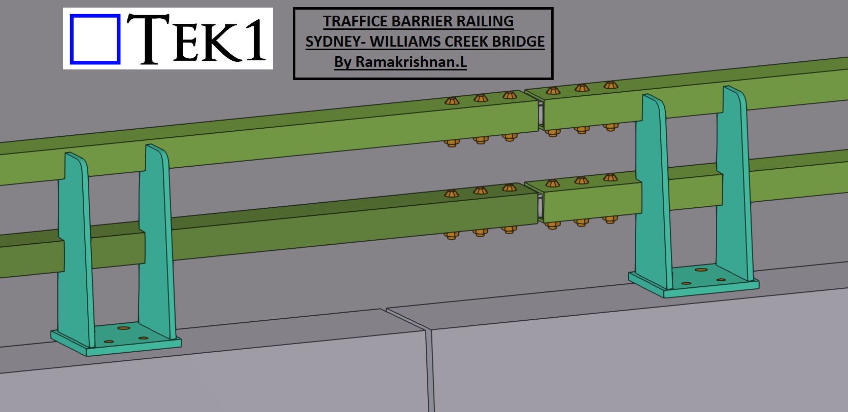
Structural Integrity: The railings are designed to withstand significant impact forces while maintaining their position and alignment.
Ease of Installation: Modular detailing allowed for efficient installation on-site, reducing time and labor.
Compliance: All railing connections were developed in accordance with Australian standards, ensuring public safety and long-term reliability.
Conclusion
TEK1’s work on the William Creek Bridge reflects our commitment to enhancing public infrastructure through precision detailing. By focusing on both safety and functionality, we’ve delivered a barrier railing system that meets the highest standards.
Stay tuned for more updates as we continue to contribute to impactful projects that make a difference in our communities.
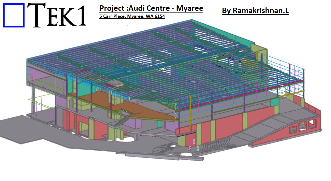
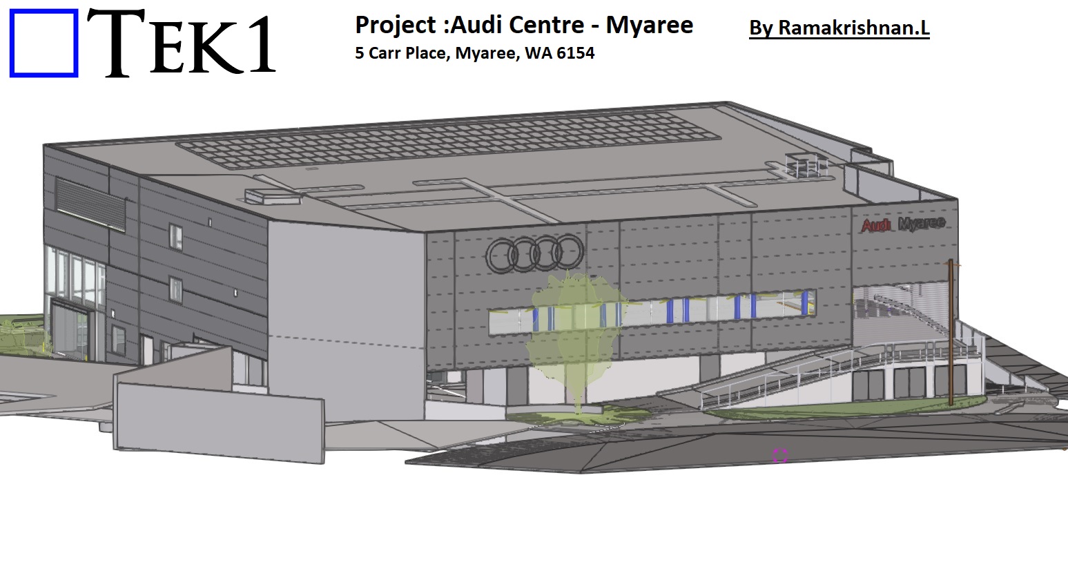
TEK1 recently completed the project Audi Centre Myaree a Audi Car showroom in Western Australia. This impressive structure is a 100-tonne steel building, featuring two floors and a main roof, exemplifying modern design and engineering precision.
Scope of Work: Steel and Precast Panels
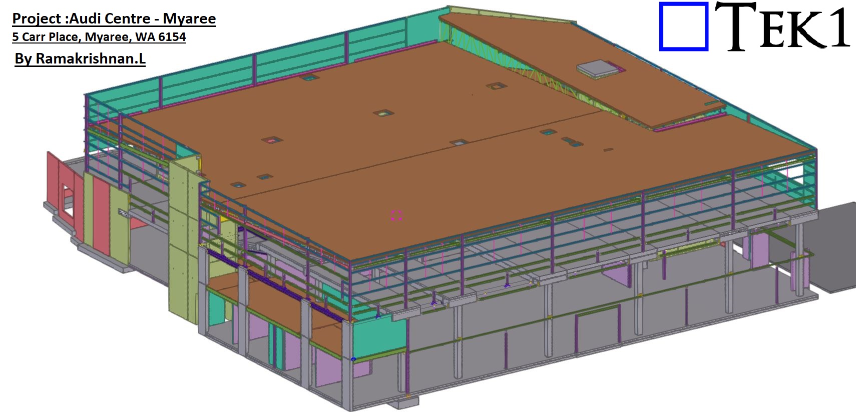
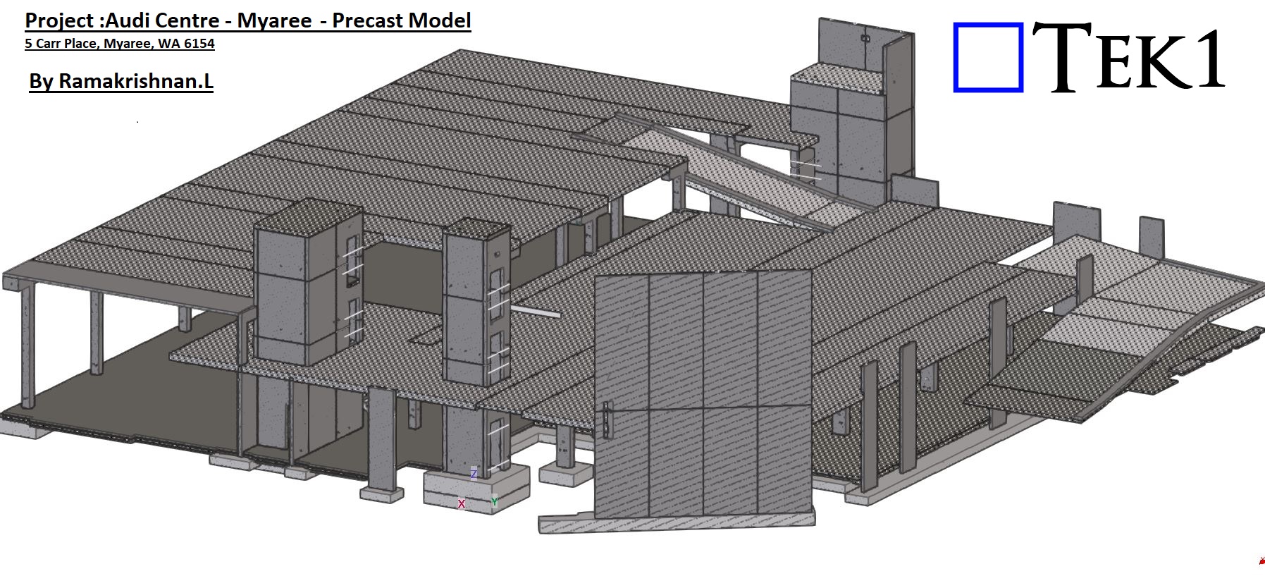
Our scope for this project included detailing both steel and precast panels. Managing these two critical elements simultaneously required meticulous coordination and attention to detail. The integration of steel and precast detailing enabled us to ensure accurate connections between the two systems, delivering a seamless result.
Overcoming Challenges with Precision
Handling both steel and precast in a single project can often lead to coordination challenges. However, thanks to TEK1’s skilled team and advanced detailing processes, we completed the project without any hitches. Our approach ensured that all connections were detailed precisely, aligning perfectly with the design and site requirements.
Precast Model
Conclusion: A Milestone in Steel Detailing
The Audi Centre Myaree stands as a testament to TEK1’s ability to manage complex projects involving multiple structural elements. By combining expertise, coordination, and a commitment to excellence, we delivered a showroom that reflects the high standards of the Audi brand.
At TEK1, we continue to set benchmarks in steel and precast detailing, ensuring that every project we undertake is marked by efficiency, accuracy, and success.
Bridging is commonly used to tie purlins together, and while structural engineers specify the type of bridging in the design, it’s up to the detailer to adapt it based on the purlin arrangement. In this blog, I’ll share how we handled a bridging connection scenario involving a concrete wall.
If you want to know ,more about bridigng. See our previous videos
Typically, bridging is tied to steel beams at one end. However, for this project, the client requested that the bridging be tied to a concrete wall instead, as there was no direct steel connection point available.
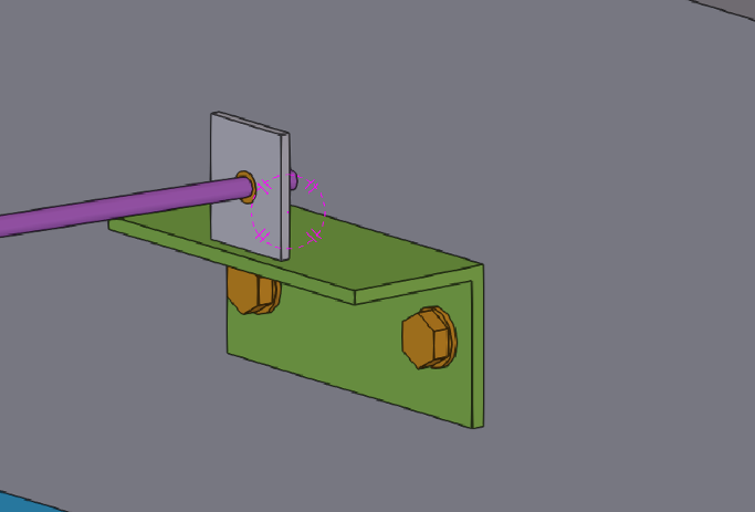
To meet the client’s request, we designed an additional support system: Equal Angle Support: An equal angle was anchored to the concrete wall using chemset bolts.
Welded Plate: A plate was welded on top of the angle to serve as the connection point for the bridging.
Bridging connections require careful consideration, especially when working with non-steel elements like concrete walls.
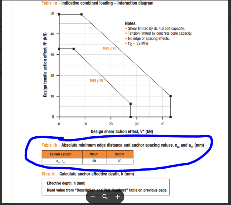
Please note that the spacing and edge distances given in the ferrule tables is for design purposes only and not a minimum for actual installation. That is the dimensions given are for each insert to achieve 100% capacity. They can be placed closer. It just means their combined capacity will be reduced. The same is for drilled and epoxied bars.
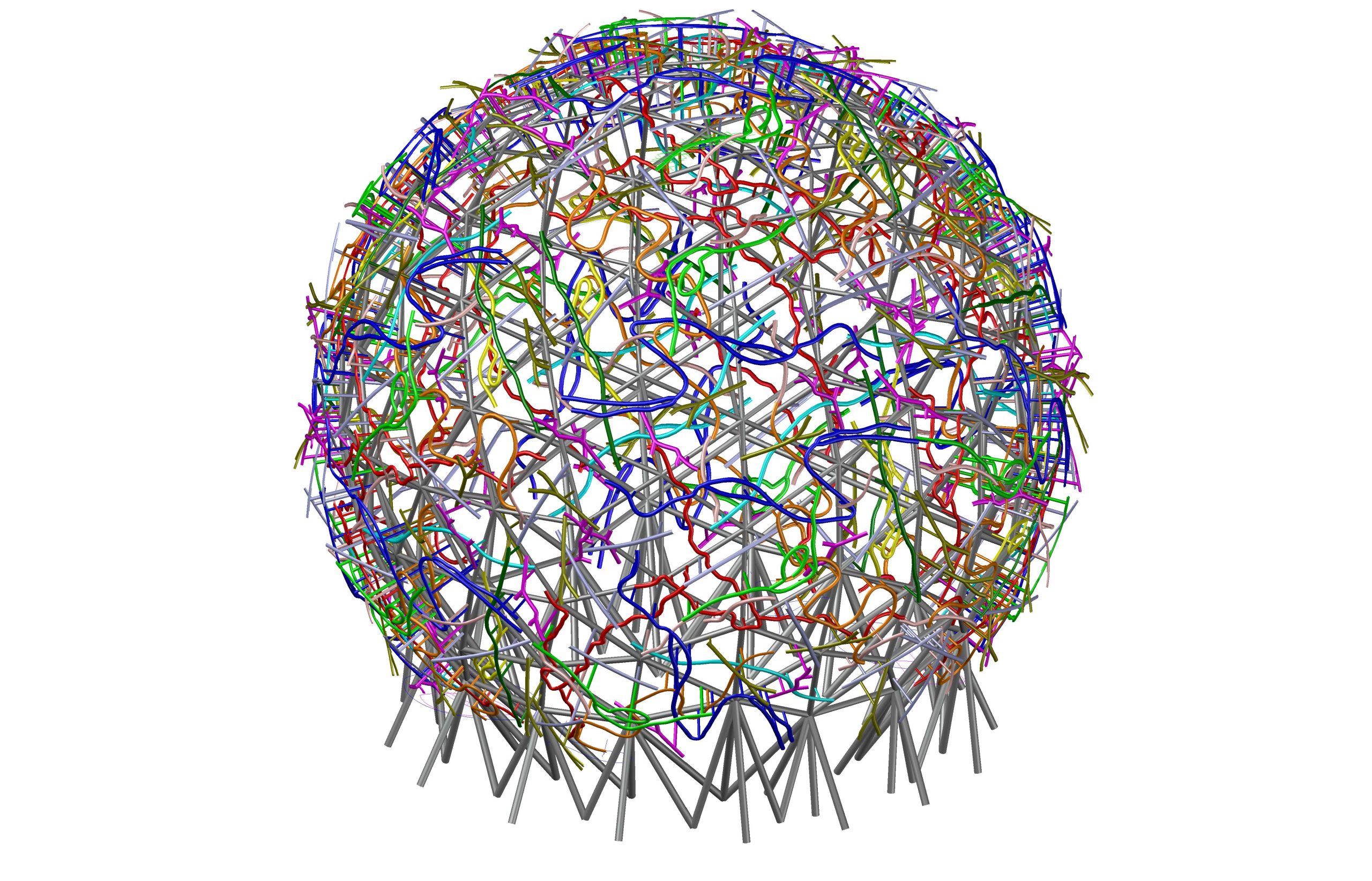
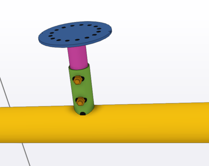
Continuing from our previous blog on the EMU IN THE SKY project, this post delves into the challenges and solutions for positioning the branches into the globe structure.
Challenges with the Original Design
The initial structural design, while visually impressive, posed significant challenges during the erection phase. The lack of tolerance in positioning the branches made the process more complicated, increasing the risk of errors and time-consuming adjustments.
EMU team proposal
To overcome this, the team introduced:
Circular Plates with Holes: A circular plate with pre-drilled holes was introduced, allowing for precise alignment of the branches.
Slotted Holes in the Outer Stub: Slotted holes were added to the outer stub welded to the globe. This innovation offers adjustable positioning, making the assembly process significantly easier and more efficient
In this method we can place the branches plate in any rotation.
Why This Design is Feasible
The updated design not only simplifies the erection process but also reduces the likelihood of rework. The added tolerances ensure that branches can be positioned accurately with minimal effort, saving both time and resources.
Stay tuned for more updates on the EMU IN THE SKY project as we continue to share insights and innovations from this iconic endeavor.
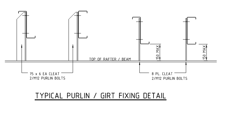
There are recommended maximum heights for purlins and Girts. If you want more heights the options are increase cleat thickness ore change cleat profile to may be equal angle profile.
Expert steel detailers will know what to do and will use the appropriate thickness and profile
If you are using 8 mm plate cleat, you can go upto 150 mm max
Beyond that use an EA cleat
75×6 EA is good.
Increasing plate thickness may not be a good option because of PB30 bolt where the bolt length is only 30 mm.
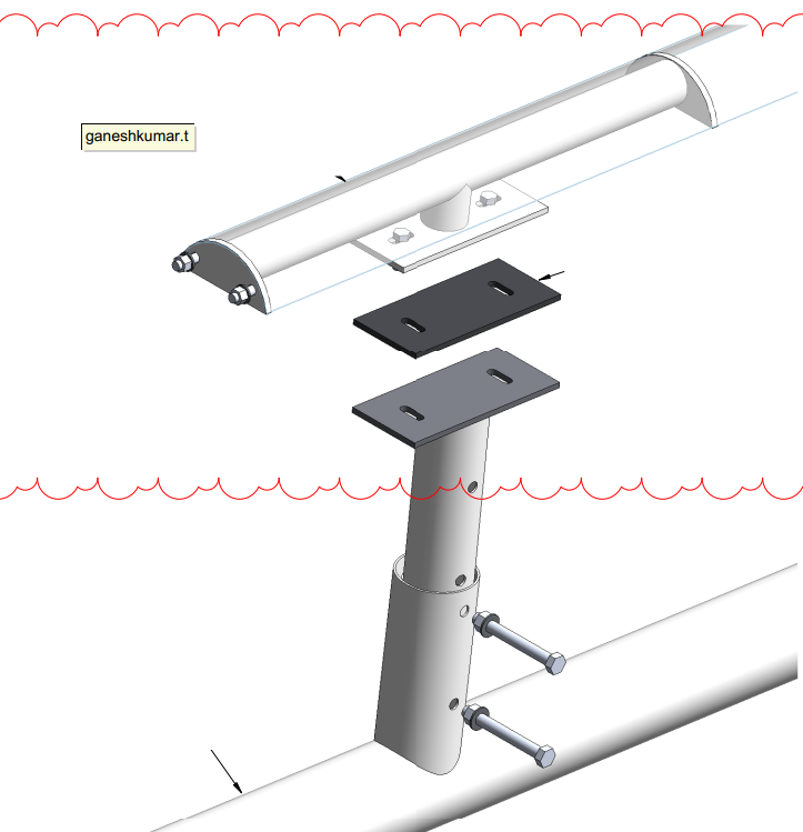
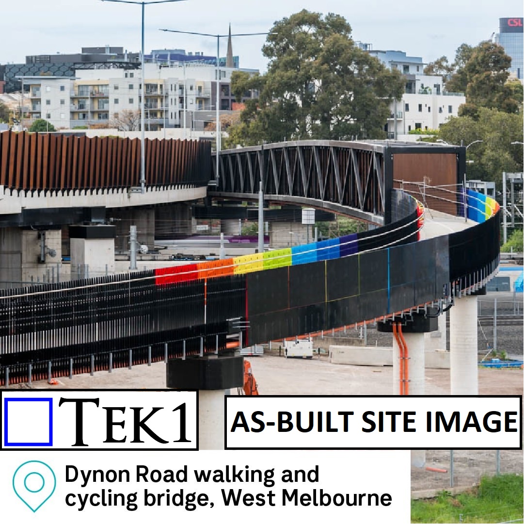
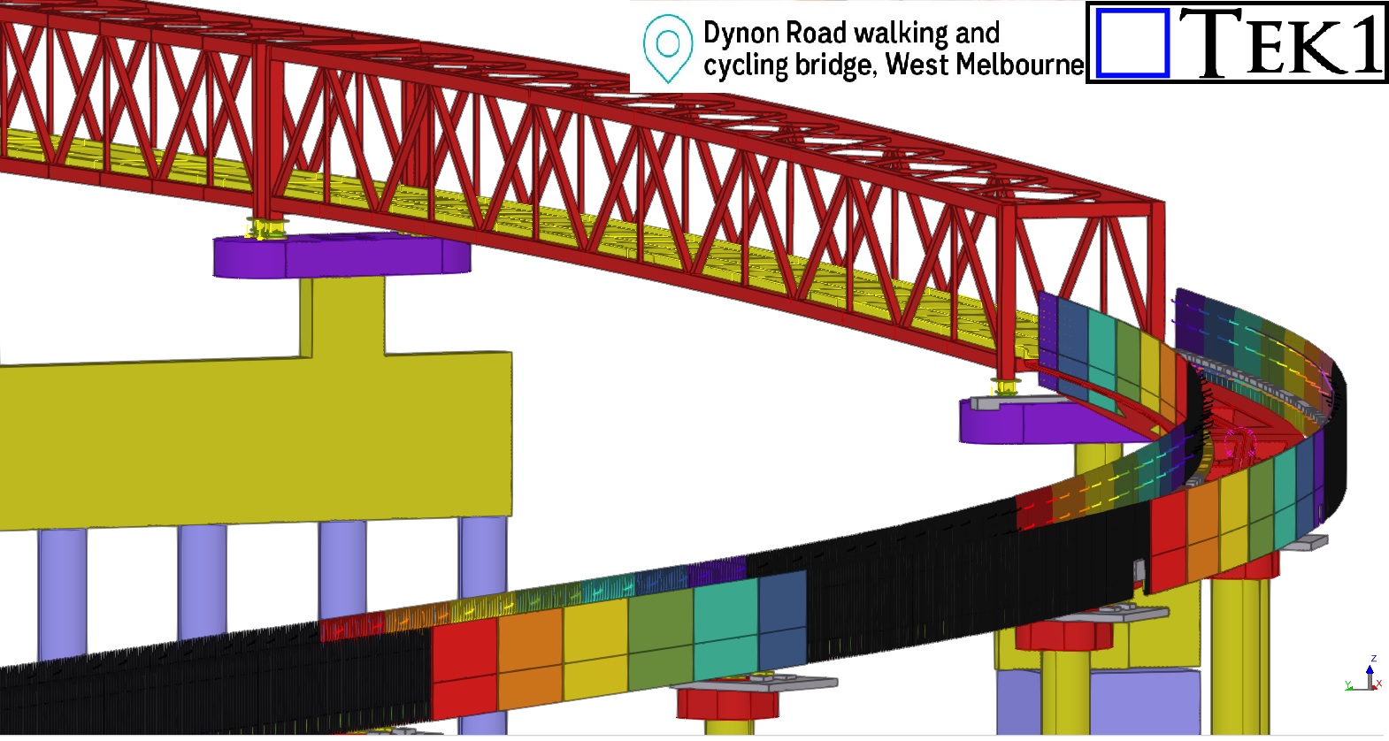
Workshop drawings for balustrades of Bridge#84 Dynon Road Walking & Cycling bridge, West Melbourne.
The fabrication drawings for the 230-meter-long balustrade panels, which feature vibrant, rainbow-colored finishes were delivered with NIL mistakes and on time.
Challenges in the As-Built Stage
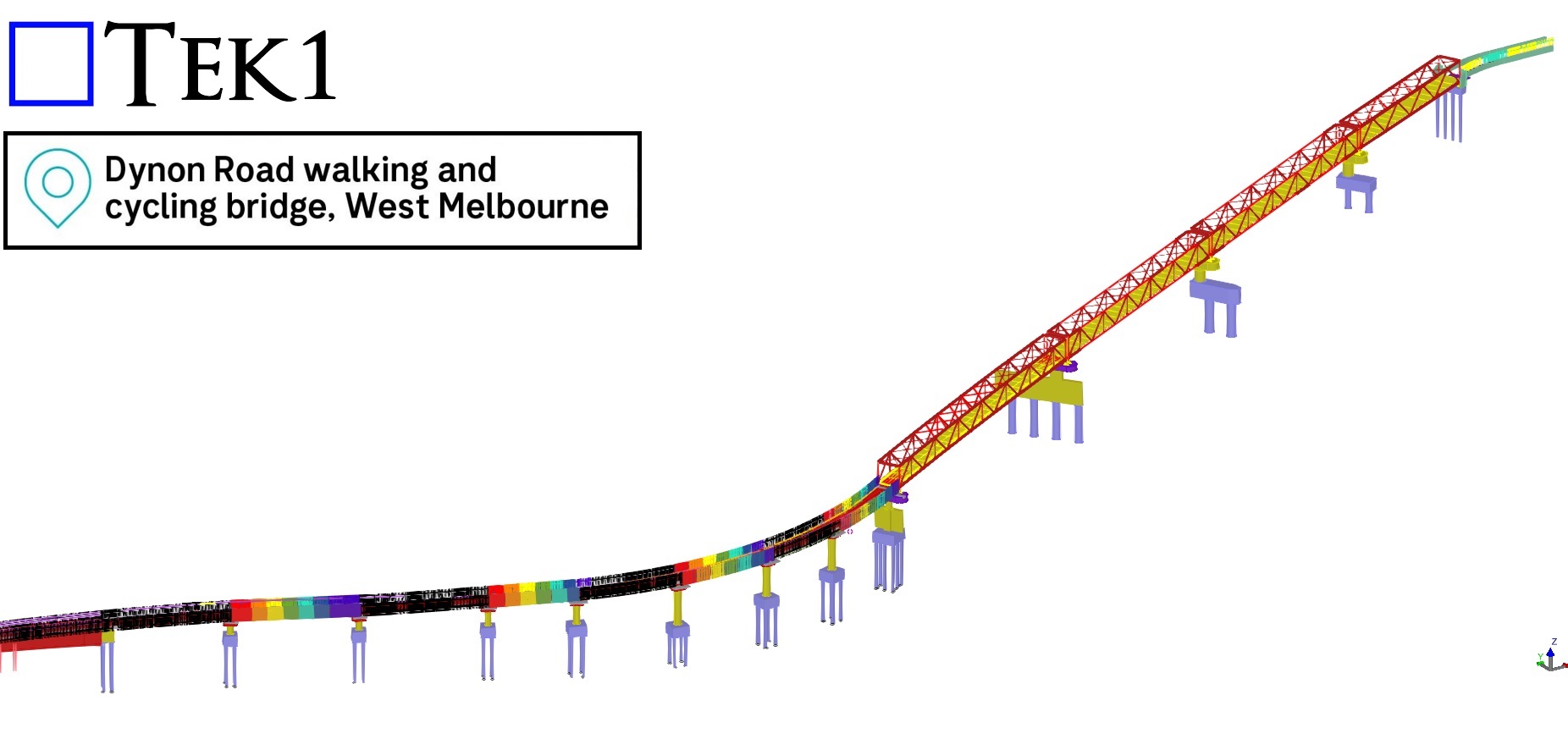
One of the most intriguing aspects of this project was the challenge posed by the as-built ramp slope and its curve, which deviated significantly from the original design coordinates. These deviations added a layer of complexity to detailing the balustrades, as each panel had to align perfectly with the precast kerbs.
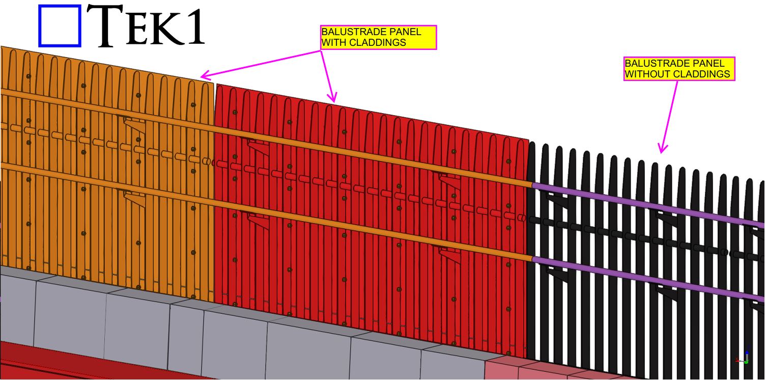
To address this, we worked closely with the builder and requested precise site measurements. These measurements were essential for us to adjust our detailing to account for the as-built ramp’s unique coordinates, ensuring every panel fit perfectly into place.
Tailored Solutions for On-Site Realities
The balustrade panels were fixed to the precast kerbs using as-built ferrules, demonstrating the adaptability required in projects where site conditions differ from the initial design. By leveraging the site measurements provided, we completed the detailing of all balustrades with precision, overcoming the complexities introduced by the ramp’s deviations.
Conclusion:
The Dynon Road Walking & Cycling Bridge is not just a pathway; it’s a vivid example of how meticulous detailing and innovative problem-solving can overcome challenges to deliver exceptional results. Its rainbow-colored balustrades are now a standout feature in West Melbourne, adding vibrancy and charm to the community.
This memo clarifies the process for handling drawing approvals and issuance to ensure project coordination and minimize potential errors.
Drawing Approval Reviews:
When receiving approved drawings, carefully review them for any markups that may significantly impact other trades or existing structural elements (e.g., slabs, foundations, anchor bolts).
Example: If an approved drawing introduces a slab pocket where none existed in the original design, ensure the following steps are taken:
Verify Slab Status: Issue an RFI (Request for Information) to determine the current status of the slab construction.
Coordinate with Relevant Parties: Communicate the design change to the construction crew responsible for pouring the slab.
Provide Updated Drawings: Issue revised slab drawings reflecting the pocket addition.
Failure to take these steps can lead to costly rework and project delays.
Issuing Drawings Before Approval:
Construction drawings should only be issued prior to approval if specifically requested by the client. In such cases, the drawings must be clearly marked and include a disclaimer.
Scenario 1: Client Does Not Require “For Construction” Marking
Issue a full set of drawings marked “Issued for Approval” (IFA).
Include a disclaimer stating that the drawings are not yet approved and their use is at the client’s own risk.
Include a disclaimer stating that the client was informed of the drawings’ unapproved status but requested them for construction at their own risk.
Obtain a written statement from the client acknowledging their request and acceptance of responsibility.
This process ensures clear communication and accountability in the drawing issuance process, mitigating potential risks associated with using unapproved drawings.
If you would like me to assist with your project, please send an email to koshy@tek1.com.au with your project specifications. Kindly use ‘Raj’ as the subject header.
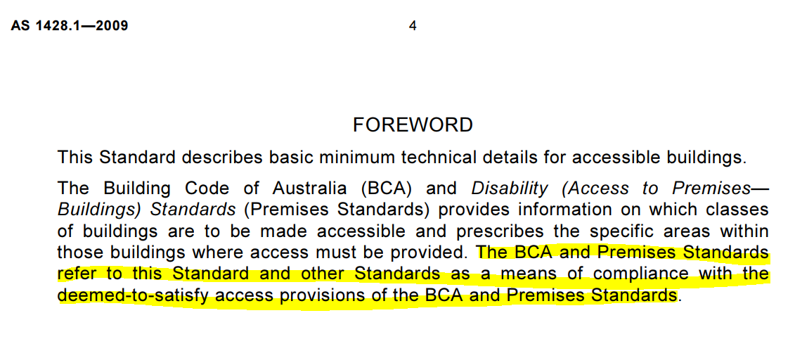
When performing detailed engineering for commercial staircases and balustrades, it’s essential to ensure that all aspects comply with AS 1428.1 and the relevant provisions from the Building Code of Australia (BCA), particularly those regarding accessibility and safety. Here’s a breakdown of the critical points you must address:
Compliance with AS 1428.1: 1. This standard outlines the minimum technical requirements for accessible buildings. Engineers must reference the BCA to align with safety and access provisions. AS 1428.1 directs engineers to follow BCA for detailed requirements related to stair and balustrade design, ensuring all safety standards are met, particularly for disabled access.
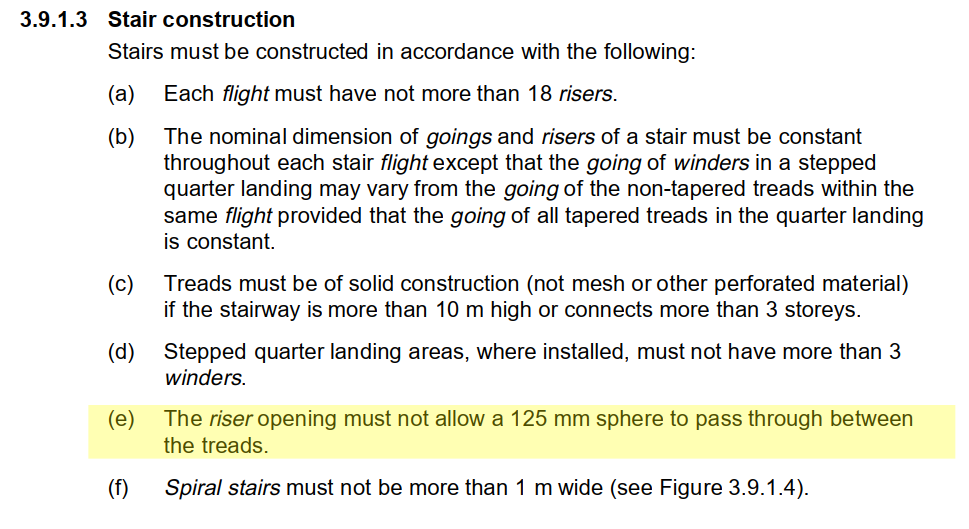
2. BCA 3.9.1.3 – Riser Opening Requirement: One of the key safety provisions under BCA 3.9.1.3 is ensuring that the riser openings on stairways are restricted. Specifically, the gap between treads must not allow a 125 mm sphere to pass through. This rule is vital for preventing accidents, such as children slipping through open risers. As a detailed engineer, you must ensure that this riser opening specification is incorporated into the technical drawings and calculations to meet safety compliance.
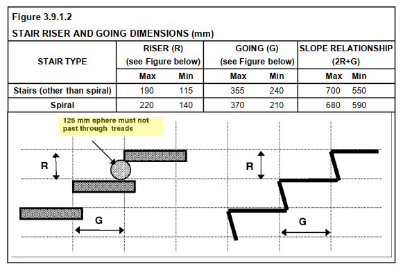
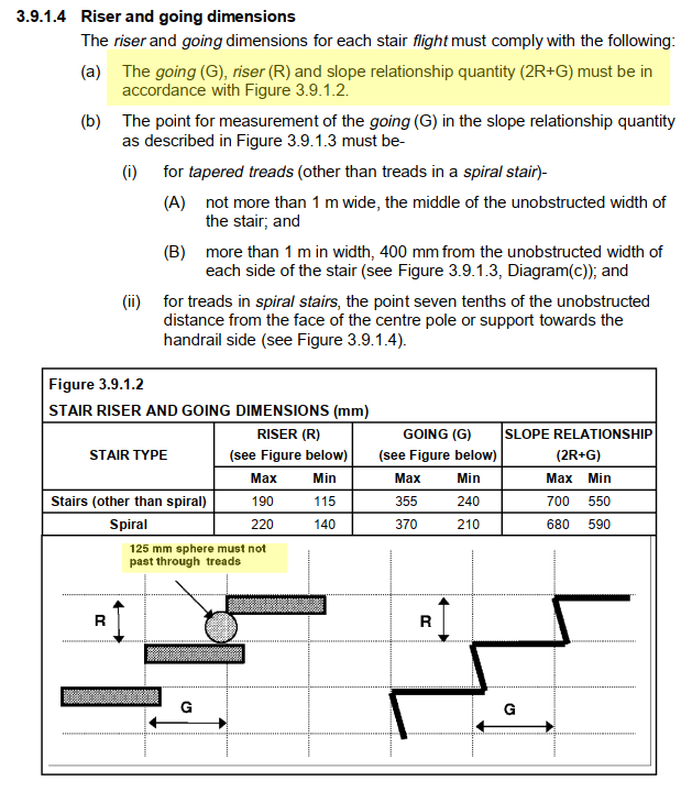
3. BCA 3.9.1.4 – Riser and Going Dimensions: Further, BCA 3.9.1.4 provides specific dimensional requirements for stair risers and goings, as illustrated in Figure 3.9.1.2. This figure shows the maximum and minimum values for risers (R) and goings (G), as well as the slope relationship (2R + G). Engineers must adhere to these dimensions for both spiral and non-spiral staircases to ensure that the stairs are not only safe but also ergonomically comfortable for users.
4. Critical Figures:
Riser (R): Must be within the maximum and minimum values—115 mm to 190 mm for standard stairs and 140 mm to 220 mm for spiral stairs.
Going (G): Must be within the maximum and minimum values—240 mm to 355 mm for standard stairs and 210 mm to 370 mm for spiral stairs.
Slope Relationship (2R + G): Must fall between 550 mm and 700 mm for standard stairs and 590 mm to 680 mm for spiral stairs. These values ensure that stairs provide both safety and comfort.
5. Ensuring Compliance: As part of the detailed engineering process, it’s your responsibility to ensure that all specifications, such as the 125 mm riser opening limit and the exact riser and going dimensions, are strictly followed in the drawings, materials, and construction processes. This involves validating these measurements on-site and ensuring they are reflected accurately in both the design and construction stages.
In conclusion, the detailed engineering process must ensure compliance with AS 1428.1 and the BCA, particularly regarding the requirement that the riser opening must not exceed 125 mm, as outlined in BCA 3.9.1.3. Additionally, the riser and going dimensions must conform to the standards specified in BCA 3.9.1.4. By adhering to these standards, you will ensure that commercial stairs and balustrades are safe, accessible, and compliant with Australian building regulations.