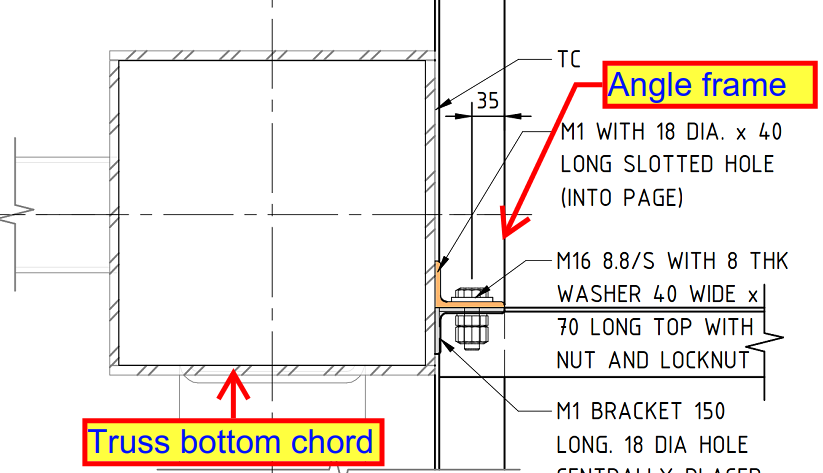
According to the design, the bottom angle (as shown in the below design) is welded to the truss chord and top angle is welded to another frame.
However, this creates a challenge when it comes to erecting the top angle, since both top and bottom angles need to be bolted together.
The all-around weld on the bottom angle complicates the positioning of the top angle, as the weld at the top obstructs proper placement.
How did we resolve the issue?
Ensure that no weld is applied at the top of the bottom angle. This makes it easier to position the top angle during erection.If the welding had already been completed, you could grind the weld at the top of the bottom angle. This would afford enough clearance for the top angle to be fitted.
If you would like me to assist with your project, please send an email to koshy@tek1.com.au with your project specifications. Kindly use ‘Raj’ as the subject header.
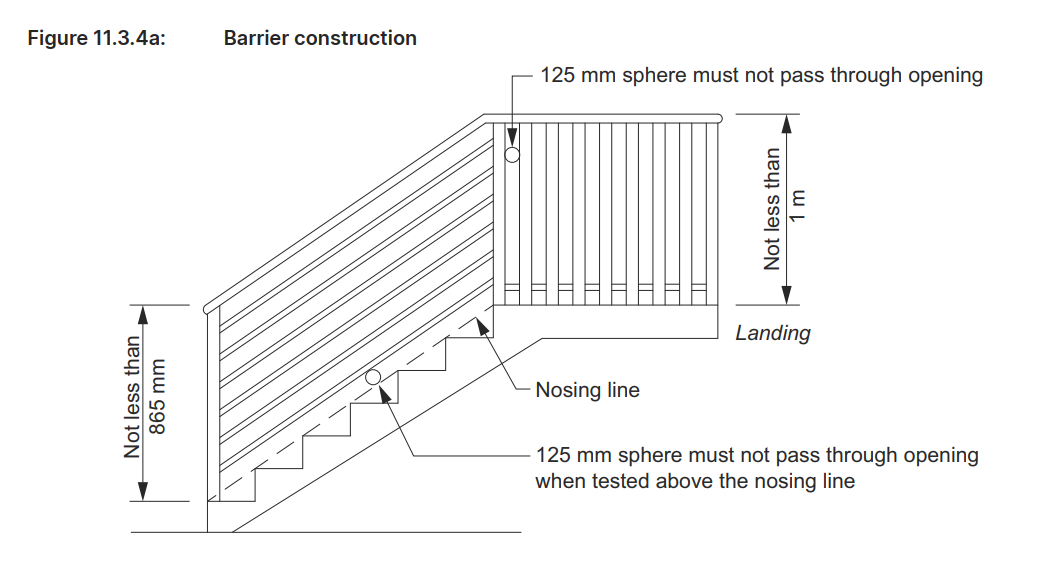
Stairs/Ramps: Minimum 865 mm above the stair treads or ramp floor. (see Figure 11.3.4a).
Other Elevated Surfaces: Minimum 1 meter for landings, balconies, and similar elevated areas. (see Figure 11.3.4a).
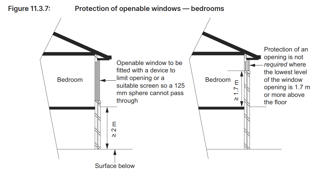
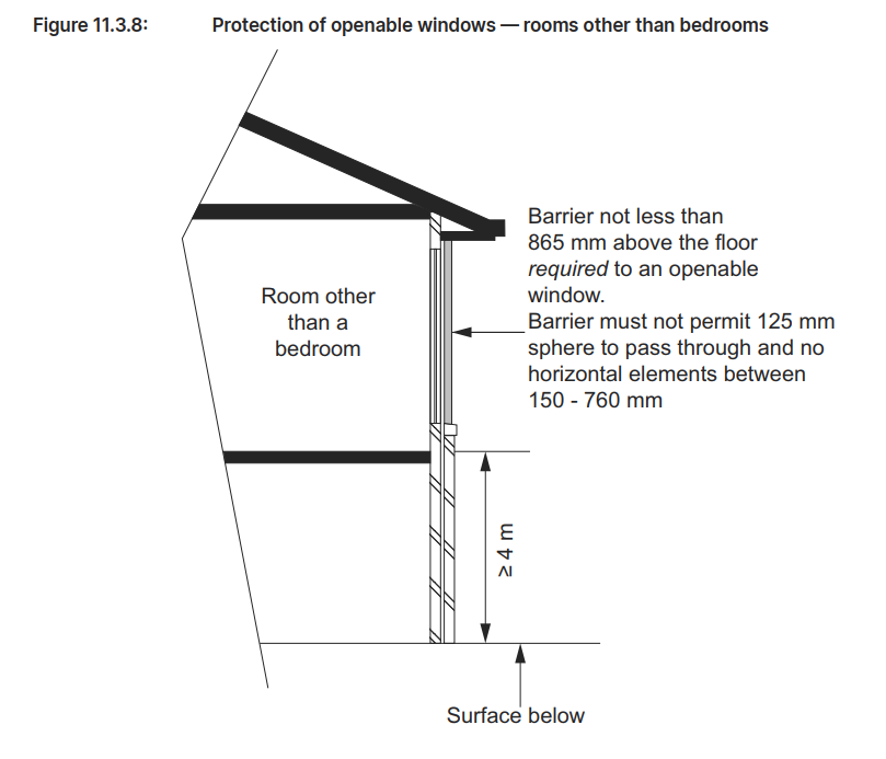
Design for Child Safety:
Openings in barriers should not allow the passage of a 125 mm sphere, the opening is measured above the nosing line of the stair treads, minimizing the risk of children slipping through. (the opening is measured above the nosing line of the stair treads)
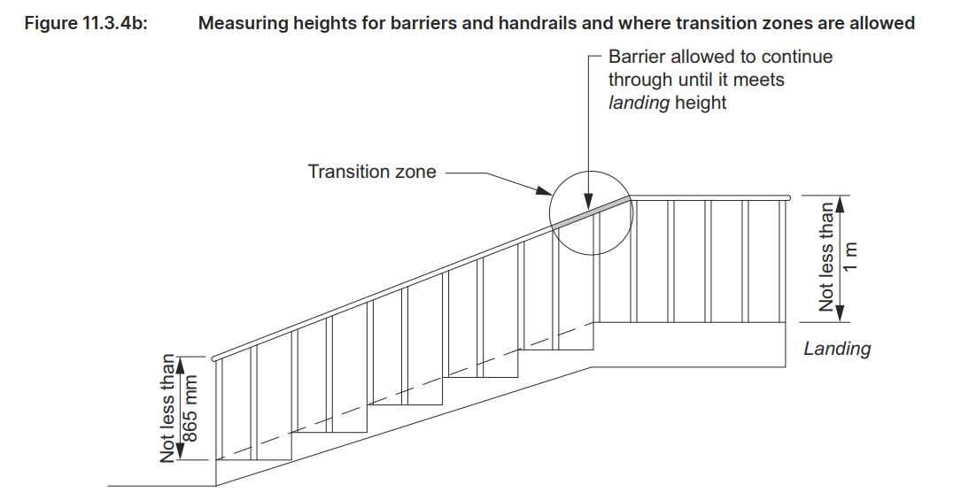
Avoid horizontal elements between 150 mm and 760 mm above the floor, as they can facilitate climbing. (see Figure 11.3.4b).
Placement: Handrails should be installed on at least one side of stairways or ramps, providing continuous support along their full length.
Height: The top of the handrail must be at least 865 mm above the stair treads or ramp surface. (see Figure 11.3.4b).
Continuity: Handrails should be continuous without interruptions, with exceptions for elements like newel posts.
Exceptions to Handrail Requirements:
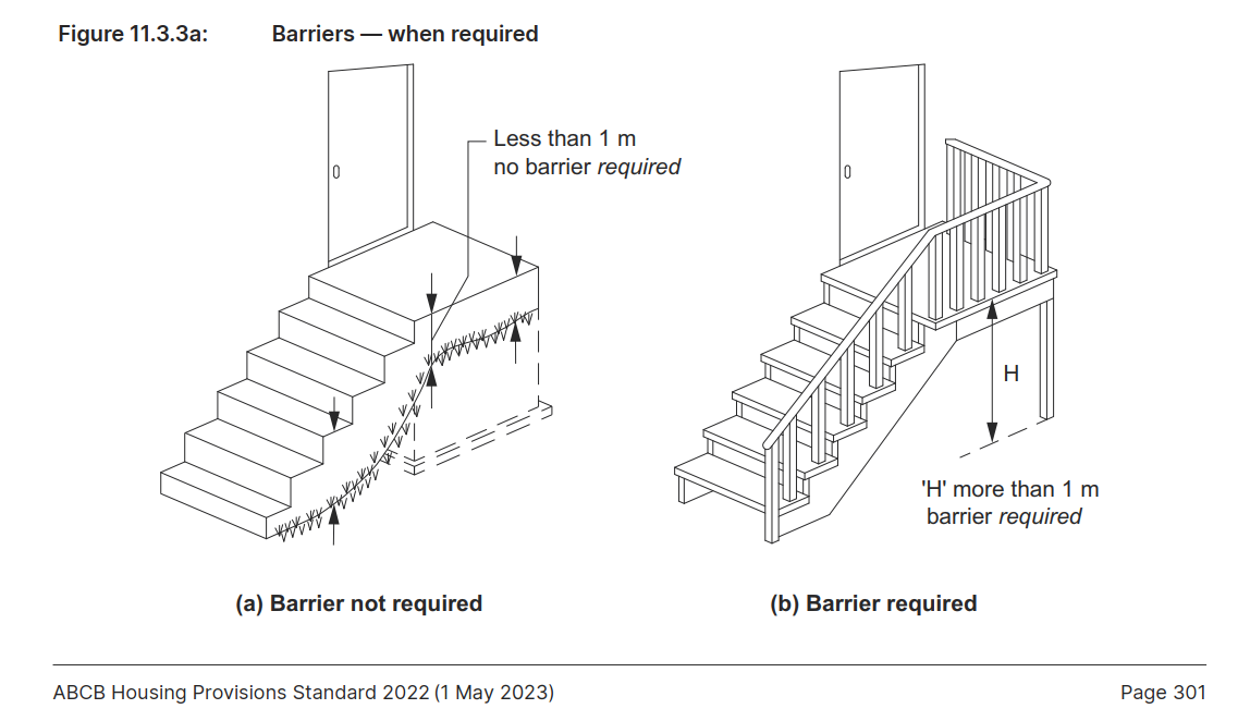
Handrails are not necessary for stairways or ramps with elevation changes of less than 1 meter, on landings, or for winders with a newel post for support
This guide emphasizes key elements in designing safe, compliant buildings that align with the Australian Building Codes Board (ABCB) standards for fall prevention, especially around barriers and handrails. These regulations aim to protect all building users, especially vulnerable groups such as children, from potential fall hazards.
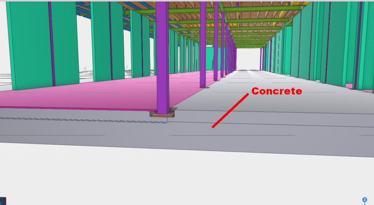
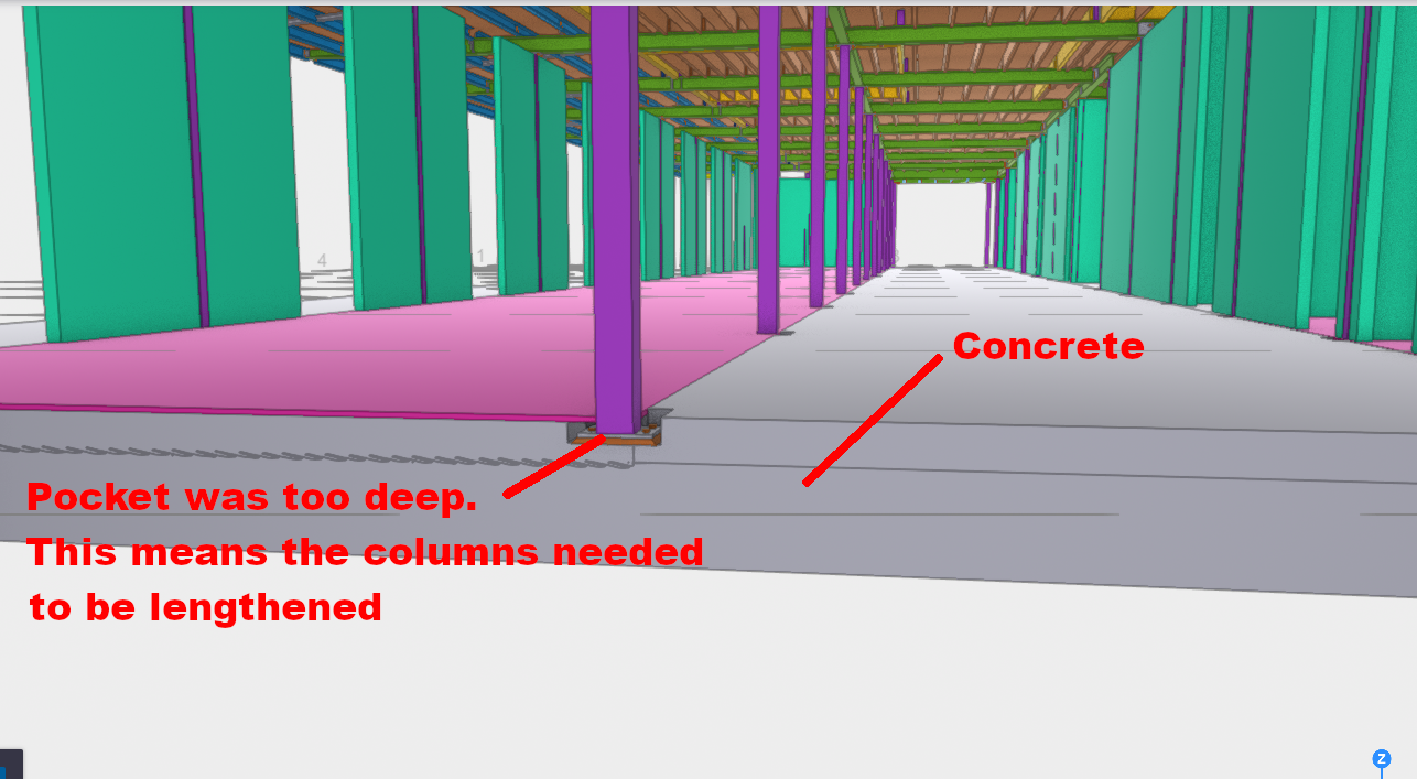
“In the world of steel detailing, failing to account for concrete variances can cost your client dearly. This case study from Duffy’s Forest serves as a vital reminder of why site surveys in steel detailing are non-negotiable. Without accurate site measurements, you risk massive on-site rectification costs—including crane hire and specialized labor crews—that can easily exceed thousands of dollars.”
Anyone who’s a detailer should be aware of this issue.
If you’re not aware: you can cost your client dearly. How?
On site rectification costs:
crane, ($500 / hour for example)
crew: supervisor, boiler makers, riggers (x2) – it become expensive.
You need operations to occur as fast as possible. This means you have to advise your client about potential issues.
Consider the following:
What is an issue that can kill your client regarding the below:
Lessons Learned:
The concrete has already been poured.
But the steel has not yet been cut and fabricated.
This means that they they can only be transported outside business hours – big trucks will slow down traffic.
Also you need a special crane to lift such large beams into place. They ain’t cheap: $600 per hour. And remember, you cannot just hire it for one hour, you have to hire it for an entire day / week.
If there’s a problem with the cleat, then you might find it difficult to fix on site. This means you have to bring the beam back down to the ground. Where are you gonna keep it?
Are you going to send the truck away? Of course not – you’ll need the truck.
And you’ll need the crane for an extra day.
And you’ll need to pay overtime rates.
……..so the question is, if something goes wrong, who’s carrying the can?
What should you do?
Make sure everyone’s on the same page. Seek an approval from the engineer. When everything’s fine, then party keeps going. But when there’s a mistake, and huge costs, and liquidated damanges, fingers will be pointed.
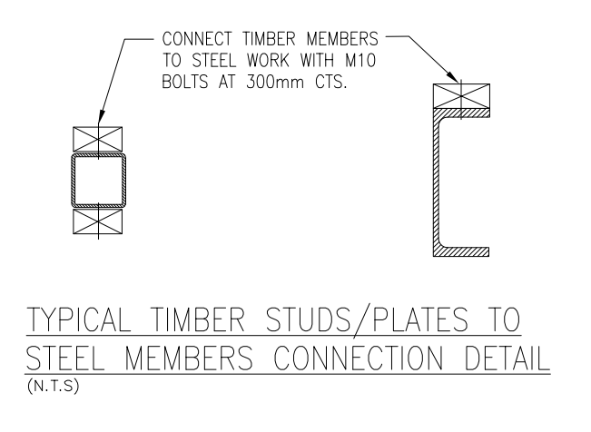
Addressing Design Discrepancies in Fixing Timber Wall to Steel Structures: An RFI Necessity
When it comes to construction projects, precision and adherence to design specifications are critical. However, sometimes, practical considerations highlight the need for adjustments to those specifications. One such scenario involves the fixing of a timber wall to steel SHS columns and beams, where the original design calls for M12 bolts spaced 300 mm on centers.
The Issue with 300 mm Spacing
While the design specifies M12 bolts at 300 mm centers, this spacing is notably narrow for this type of application. Typically, such close spacing is reserved for situations where exceptional load-bearing capacity or additional structural support is required. In this context, a spacing of 600 mm on centers would be more than sufficient to secure the timber wall effectively, without compromising structural integrity.
The concern with the 300 mm spacing is not just overengineering but also the practical implications on the job site. Implementing such close spacing requires more materials, labor, and time, leading to increased costs and potential delays. Moreover, drilling excessive holes into steel SHS columns for fixing purposes could weaken the structural integrity of the columns, which is an outcome that must be avoided.
Alternative Solution: Gun-Fixing the Studs
Given that the primary objective is to secure the timber wall to the steel structure, an alternative approach could be considered. Gun-fixing the timber studs directly onto the steel columns, without the need for drilled holes, is a viable option. This method is not only faster but also maintains the strength of the steel columns by avoiding unnecessary perforations.
Raising the Issue: The Importance of an RFI
Before proceeding with the job, it is essential to address this issue through a Request for Information (RFI). An RFI will formally document the concern regarding the overly narrow bolt spacing and propose the alternative method of gun-fixing. By raising an RFI, the project team can seek clarification and approval from the design engineers or the client to adjust the specifications accordingly.
This step ensures that all parties are aligned, and any modifications to the original design are officially approved, reducing the risk of rework or disputes later in the project. It also demonstrates due diligence and a commitment to delivering a project that is both cost-effective and structurally sound.
Conclusion
In summary, while the original design calls for M12 bolts at 300 mm on centers to fix the timber wall to steel SHS columns and beams, this spacing is unnecessarily narrow. A 600 mm spacing would be sufficient, and an alternative method of gun-fixing the studs to the columns should be considered. Before commencing work, this issue must be addressed via an RFI to ensure that all stakeholders are in agreement and that the project proceeds smoothly and efficiently.
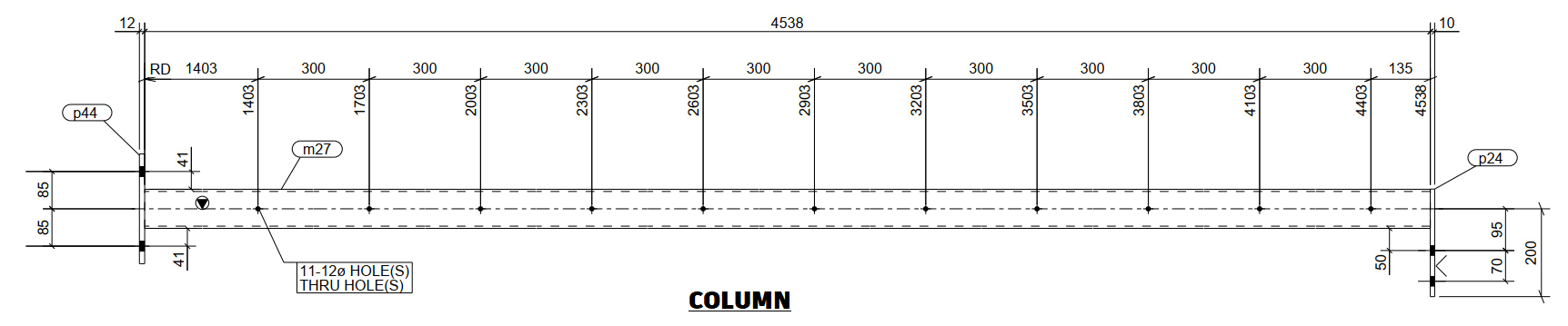
When working with elements like cladding plates, balustrade infills, decorative panels, and chequer plates, the approach to modelling them differs significantly from that used for standard structural plates. Ensuring accuracy in these cases hinges on a thorough understanding of working points and the rotation property, which are essential for ensuring the correct orientation of the visible side when generating drawings or DXF files.
Understanding the Critical Role of Working Points
It might seem simple to assume that these sheets can be flipped or rotated as needed after they are cut. However, this is a common misconception that can lead to significant errors during fabrication. The key to avoiding such issues lies in setting up the working points correctly, particularly when dealing with intricate designs or surface finishes.
The Importance of Proper Rotation
Take a stair panel, for example. If the panel features any patterns or surface differences, the working point must run in the direction from left to right when facing the stair panel. Additionally, the rotation must be set to either “top” or “front”—never “bottom” or “back.” This ensures that the visible side of the panel is correctly positioned.
Symmetry Doesn’t Eliminate the Need for Attention
Even in cases where the pattern is symmetrical or there appears to be no pattern at all, the orientation of the face of the sheet is crucial. It’s easy to think that since the machine will cut the plate according to the DXF file, it doesn’t matter how the drawing is flipped or rotated. However, this is where problems can arise.
Avoiding Aesthetic Imperfections
During the cutting process, the machine can leave minor marks on the material. These marks are typically left on the non-visible side of the sheet. Therefore, it’s critical to feed the sheet into the machine with the correct side facing outwards. If not, the marks could end up on the visible side, compromising the aesthetics of the final product.
Conclusion: Precision is Key to Quality
Proper modelling and careful consideration of working points and rotation properties are essential when dealing with cladding plates, balustrade infills, decorative panels, and chequer plates. By ensuring the visible side is correctly oriented from the start, you can avoid costly mistakes and ensure a high-quality finish.
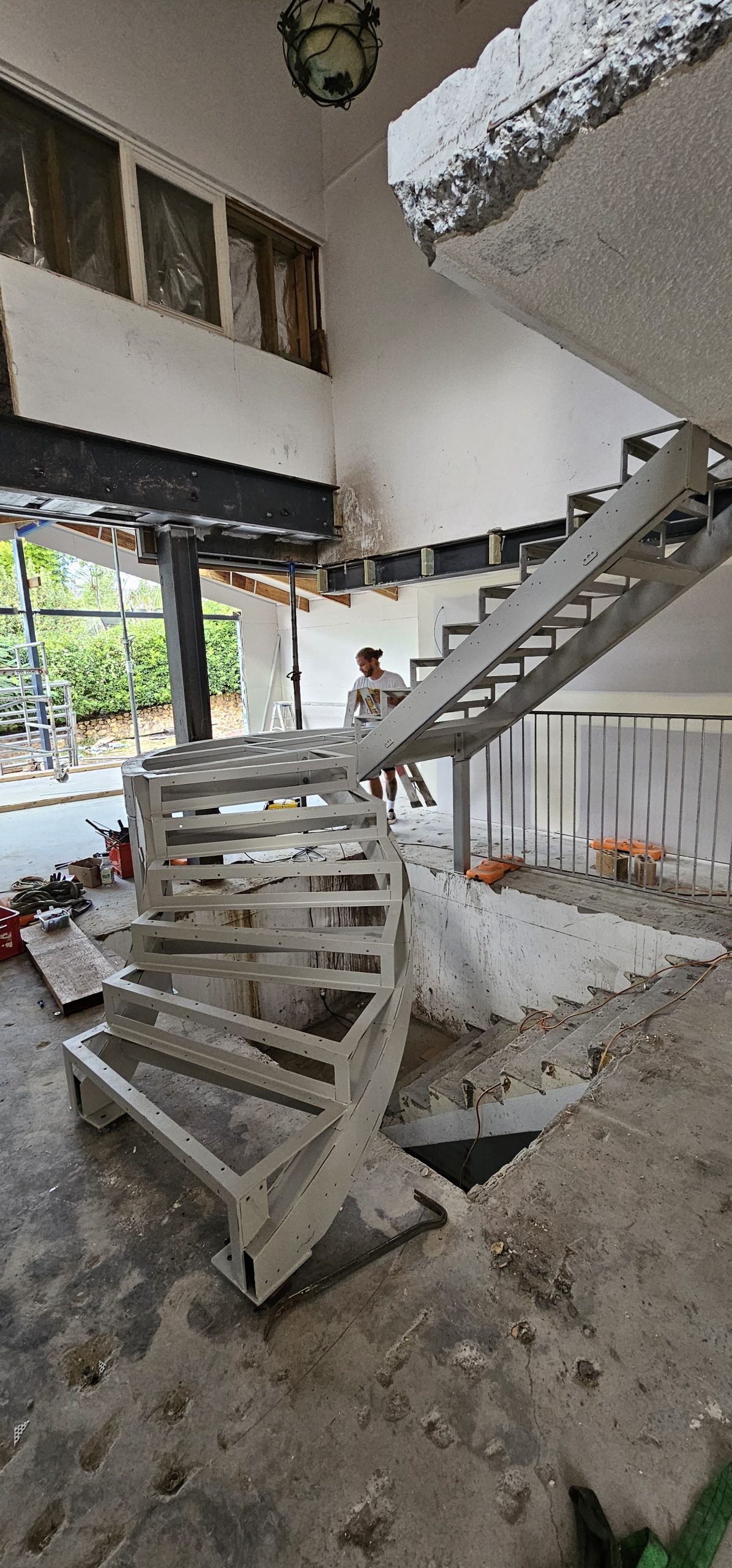
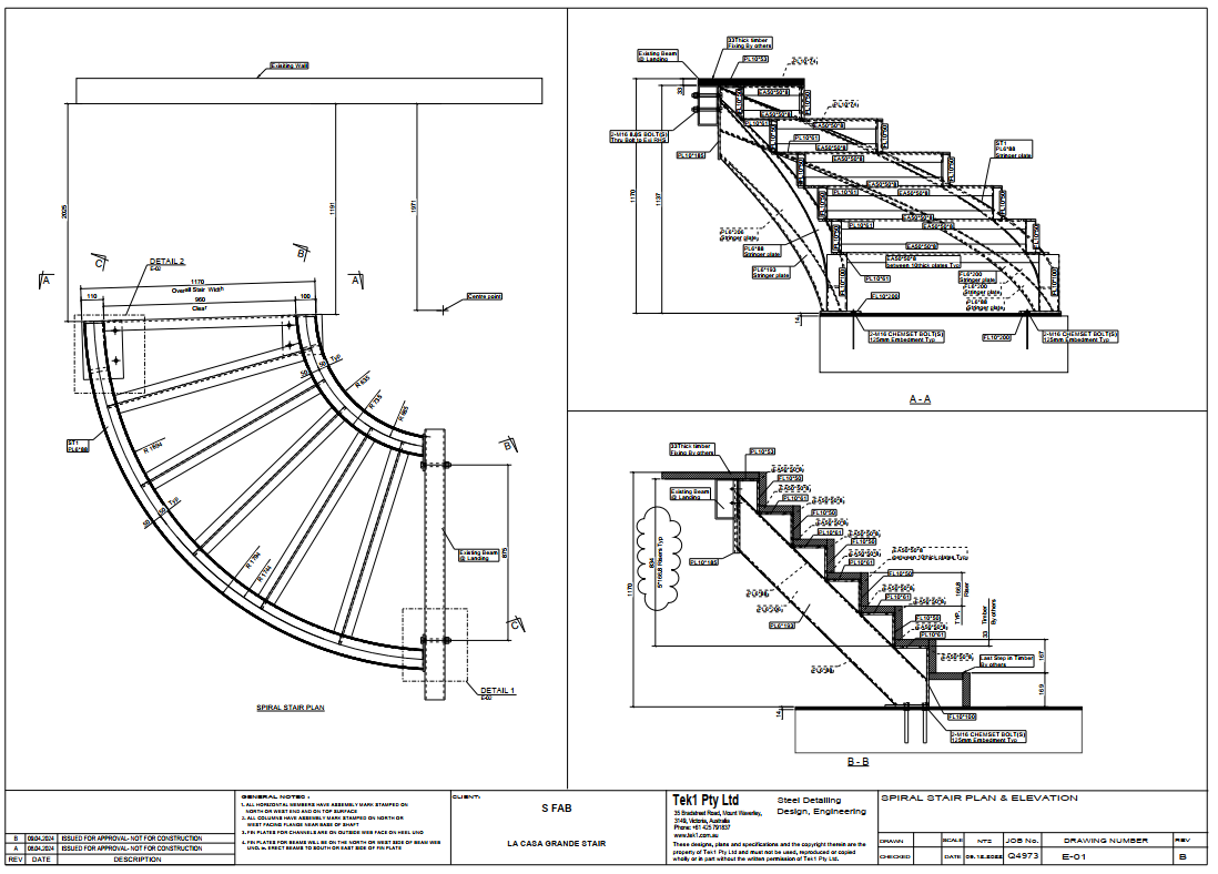
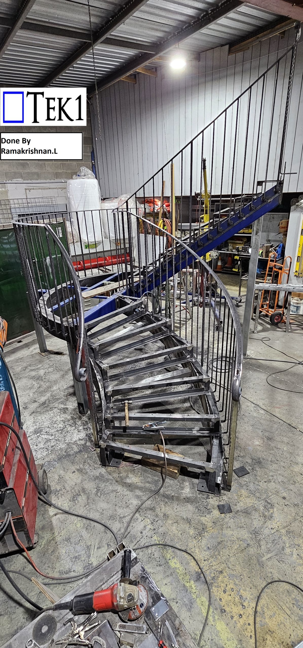
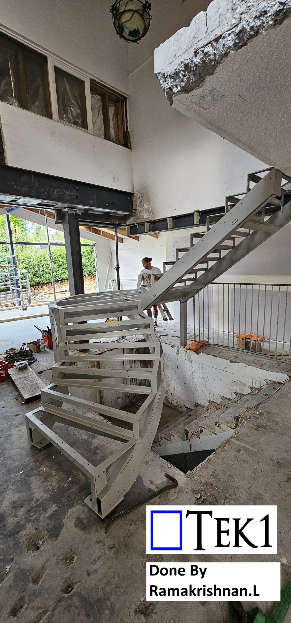
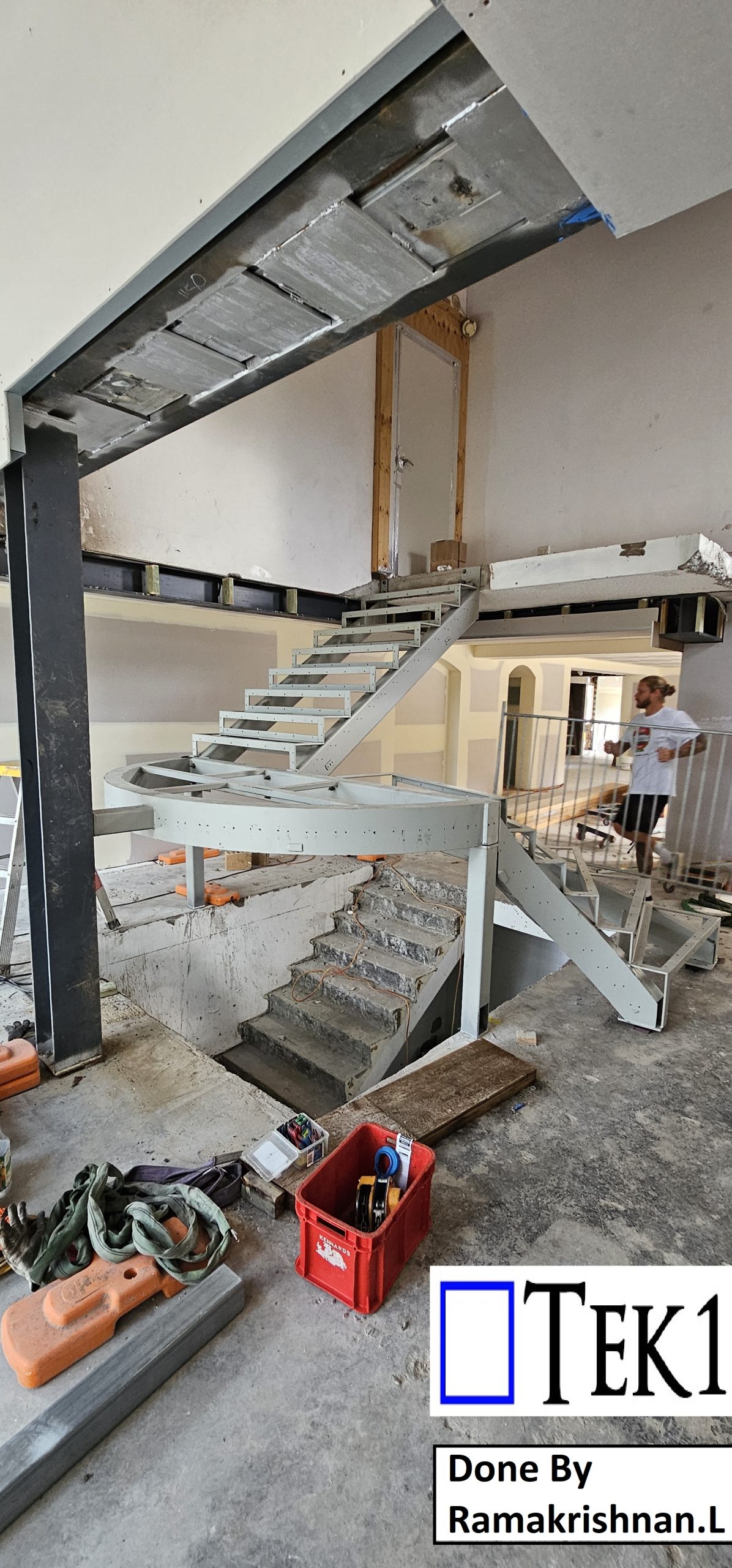
We are pleased to inform you that TEK1 has accepted the task of detailing the spiral plate-formed RHS stringer stair as requested by our client. Our team is well-equipped to handle this design, ensuring that all details meet the highest standards.
At TEK1, we have consistently provided top-notch miscellaneous steel detailing services to our esteemed clients, adhering to all relevant codes and standards. We are committed to delivering precise and reliable shop drawings tailored to your needs.
Should you have any queries related to miscellaneous steel shop drawings, please do not hesitate to contact us. We will promptly provide you with the necessary answers and support.
For any steel shop drawings you require for an ongoing project, feel free to reach out to Koshy at (03) 9560 6397 or +61 3 9560 6397.
Changes were required on the project necessitating variations – at double the cost of the original quote!
When this happens, it is ESSENTIAL that you call the client before you put in your variation documentation.
Why?
The client will suffer from “sticker shock” after he sees your price.
“Sticker shock” means that the client will be so surprised, and shocked, that he will fall off his chair.
The client will lose trust in you.
The client will try to negotiate everything down.
What should I do instead?
Call the client and say that the changes are huge.
Do not send variation documentation before addressing the “sticker shock issue”.
We cannot and do not negotiate on prices.
Going forward clients can choose between: (i) a fixed price quote – where we take on-board the risks of an infinite amount of variations, or (ii) where we charge variations but come in at a lower price.
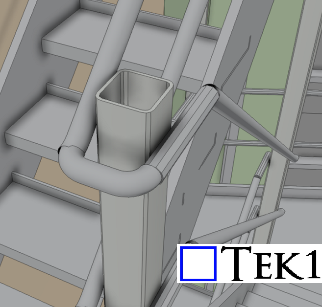
In the realm of steel detailing, it’s not enough to simply follow design drawings and IFC models. As detailers, a thorough understanding of general standards is crucial to ensure accuracy and compliance.
The Importance of Standards
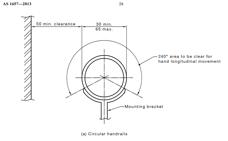
For instance, consider the Australian stair standards AS1657, which require a clear handrail area of 240° with a minimum clearance of 50mm. In the example below, the designer overlooked this standard, focusing solely on structural aspects without accounting for necessary clearances.
Identifying and Addressing Errors
As detailers, it is our responsibility to identify such discrepancies. In this case, the handrail does not meet the required clearance standards, which could lead to safety issues and non-compliance.
When we encounter designs that do not meet standards, it’s essential to raise queries with the client. This proactive approach ensures:
Compliance with Standards: Adhering to necessary safety and design standards.
Cost and Time Efficiency: Preventing costly rework and project delays. Enhanced Quality: Ensuring the final product is safe, functional, and compliant.