TEK1 Successfully done this Robinson’s bridge walkway by one time detailing without any hitch


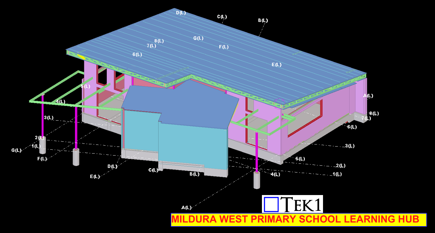
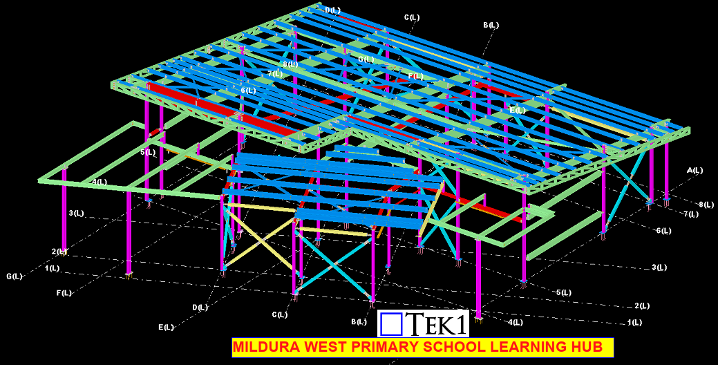
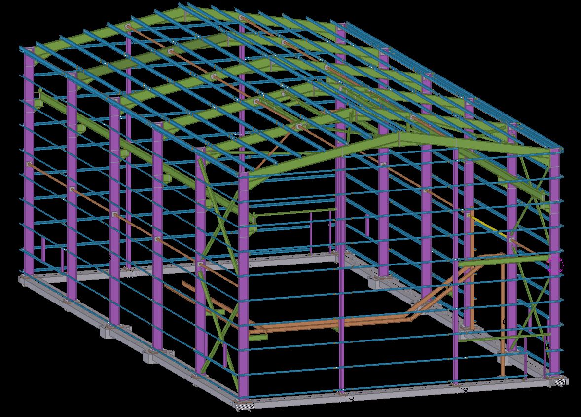
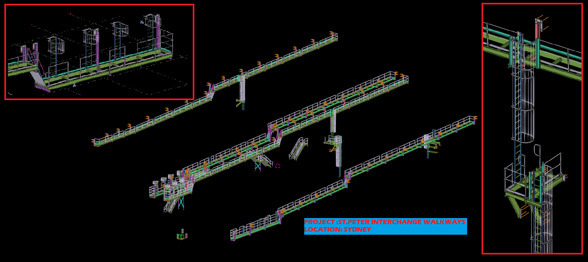
This page show cases some of the Steel Detailing projectgs completed in Melbourne, Sydney, WA, Brisbane Tek1 has completed
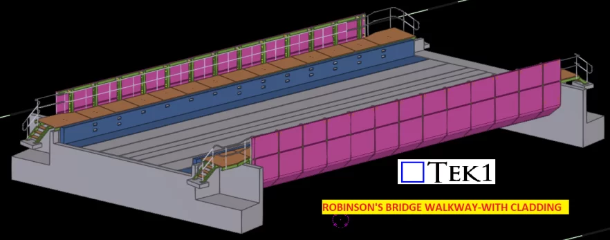
TEK1 Successfully done this Robinson’s bridge walkway by one time detailing without any hitch
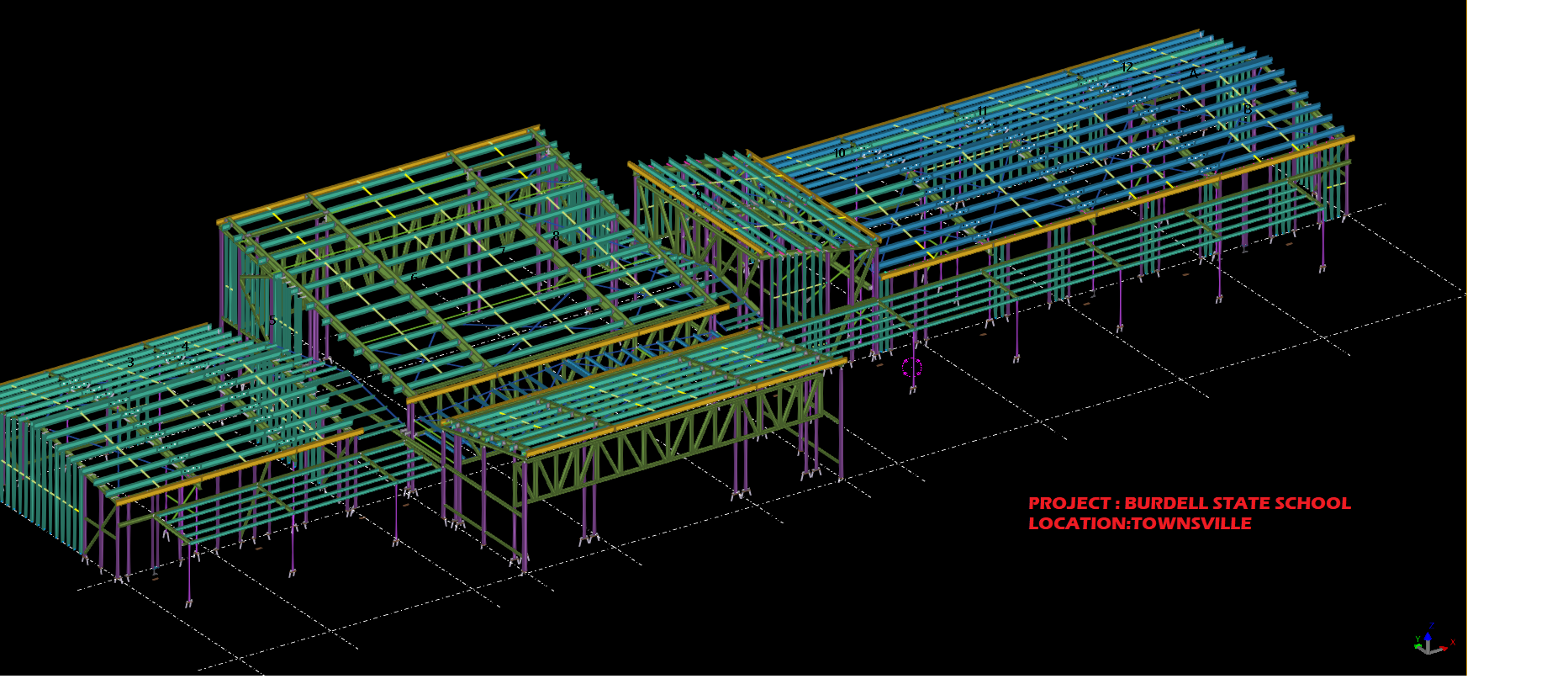
We have done steel detailing for the building called CAM inside the burdell school within a short period of time without any issue.


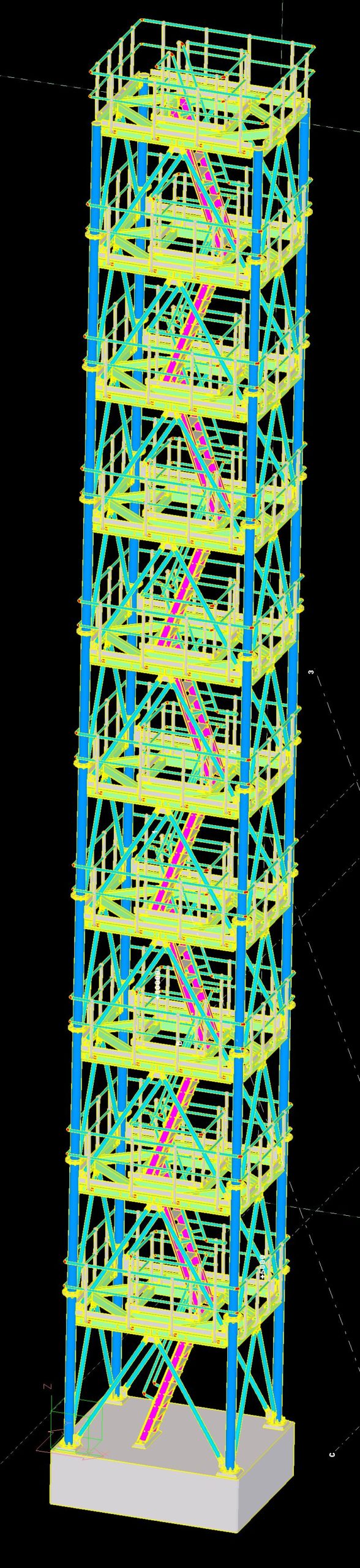
| TEK1 Successfully done this MT.ARTHUR COAL TOWER by one time detailing without any hitch |

Client query: Some of our clients ask us why the Labels for assemblies varies in our shop drawings from the labels mentioned in the Structural Engineer’s documents.
This Blog explains why this can’t be done.
Comparision with Structural documents:
Normally, In Structural Engineer’s documents the same label will be given to the members of same profile used in different instances irrespective of their other properties such as change in geometry, connection members welded to the assembly, etc.,
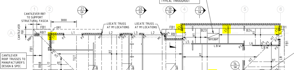
For Example: In below image, the highlighted column C1 – SHS 89*6 is used in multiple instances.
Working with Tekla Structure:
In general, This method cannot be followed while detailing because each member (even if the profile is same) will have it’s own shop drawing depending upon the change in any of its properties such as geometry, material, finish, connection members welded to the assembly & so on.
Refer below snap for clarity.
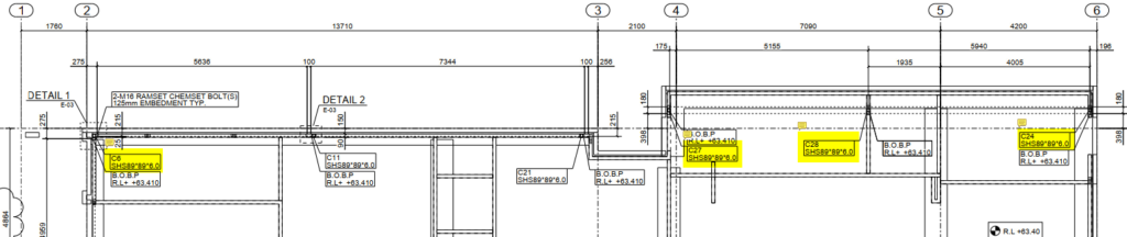
In summary, although we have used the same profile for the column C1 as mentioned in structural documents, due to the change in connecting members welded to the column and change in geometry we have provided different labels in the GA drawings.
The Golden Rule: Be very clear and specific about what you are quoting for. e.g. I am only going to work on the following (insert specific details), and everything else is excluded.
Why is this important?
Variations:
Specific Examples of Quoting:
Here are some examples, of how we quote.
Northern Retaining Wall
Detailing structural beams, connections details, according to the following scope:
Drawing 1: Type – T1 250UC90 HDG QTY: 299
Drawing 2: Type – T2-L 250PFC HDG QTY: 1
Drawing 4: Type – T2-R 250PFC HDG QTY: 1
Drawing 5: Type – T7 250PFC HDG QTY: 26
Drawing 6: Type – T8 250PFC HDG QTY: 1
EPH – Station Platform Northern Retaining Wall
Drawing 7: UC 150 x 37.2 post with base plate. QTY: 58
Drawing 8: PFC 200 with Base Plate. QTY: 4
Everything else is explicitly excluded. Changes might incur charges via variations. Fully documentation will be provided.
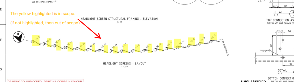
Highlight Items on a Drawing
Here is an example:
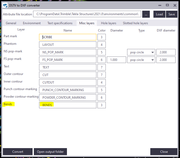
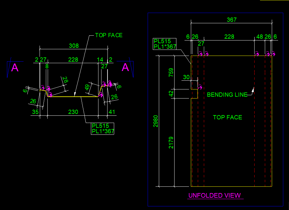
This blog illustrates how to provide the dimension detail in an efficient way for sheet metal bending using Tekla Structure. For bending of sheet metal, we need to provide add-on information in Pdf drawings and dxf files for calrity of fabricator.
By default the Tekla Structures can generate drawing with bend lines. But it is not sufficient for the fabricator, until he knows which side to bend the sheet. This can be achived using the plugin “DSTV TO DXF CONVERTER” available on Tekla Warehouse.
(Note: Always check if the drawings are created in front view for high quality output.). See below image for clarity

Steps to show bending lines:
When a DXF file is exported using Tekla it shows reference line. In order to add the bending lines we use the tool “DSTV TO DXF CONVERTER“.In this tool, there is an option to provide a bending line in a different layer on the dxf file. The output dxf files contain information in which direction the sheet has to be bent. This information can be used by the detailer and fabricator for quality output. See below image for clarity