Category: Steel Detailing Blog

This page show cases some of the Steel Detailing projectgs completed in Melbourne, Sydney, WA, Brisbane Tek1 has completed

  • Can you spot the problem – #2

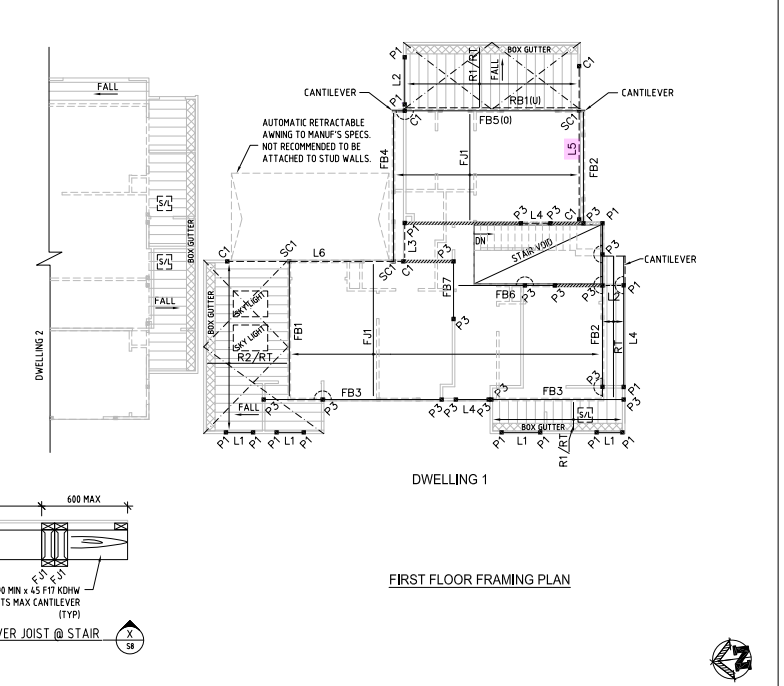
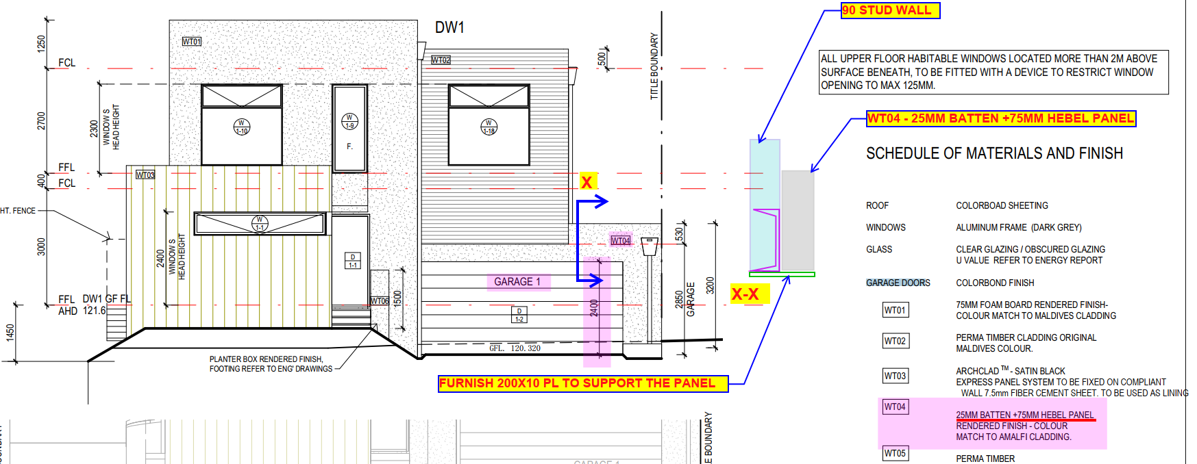
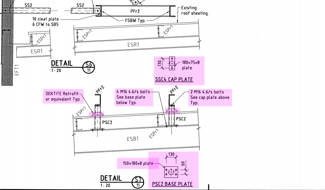
    Please study the following drawing. The engineer has called for these details. But as detailers, can you see any issues which may come up? Consider the problem carefully and let us review the issues below. (Given information: the below is a drawing of a corrugated roof. There is a deck to be placed on top of the roof. Hint: waterproofing is the primary concern).


    Can you spot any issues with the above drawing?

    What is going on here?

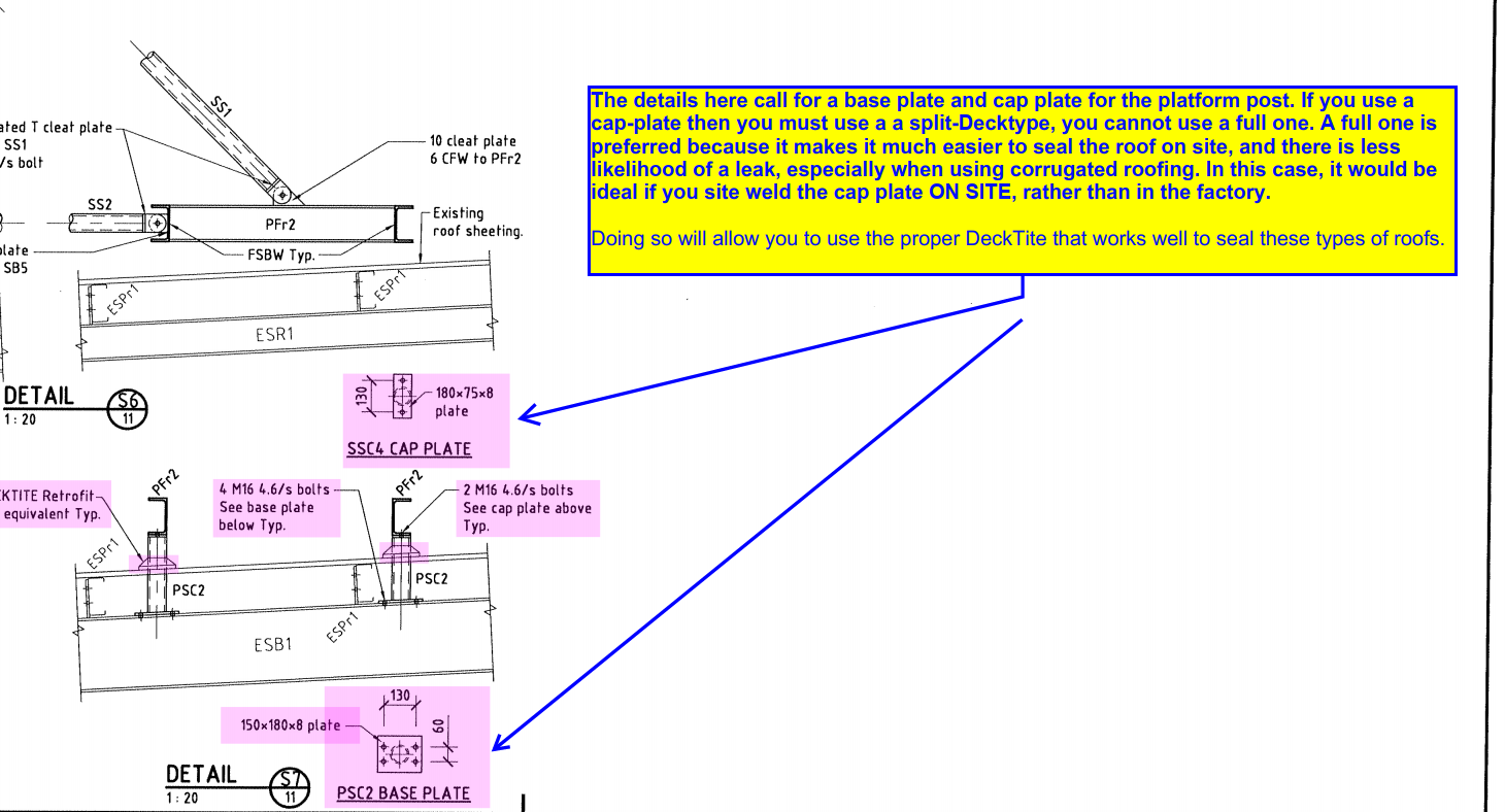
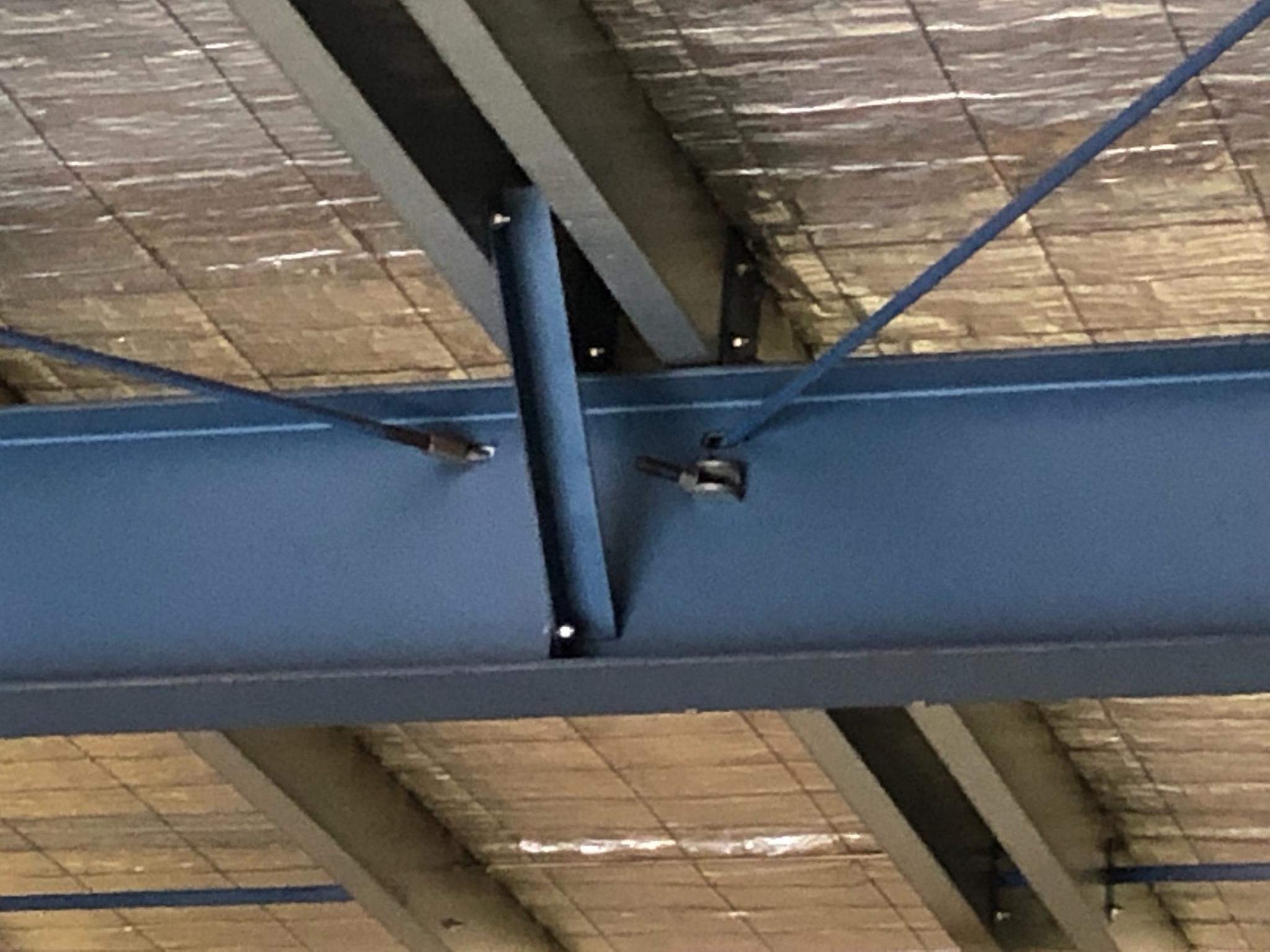
    The issue lies with water proofing. Corrugated roofing is not flat. It is bent and curved. In this case we have a beam that is penetrating through the roof. In these circumstances, water proofing is critical, and we need some type of Decktite (or equivalent) to be placed on the roof to ensure that water does not seep through. But then, what is the problem here?

    To understand this issue, you would do well to watch these two videos first:

    1. https://www.youtube.com/watch?v=SSouJZBFjTw
    2. https://www.youtube.com/watch?v=xHA-lwY7aS8

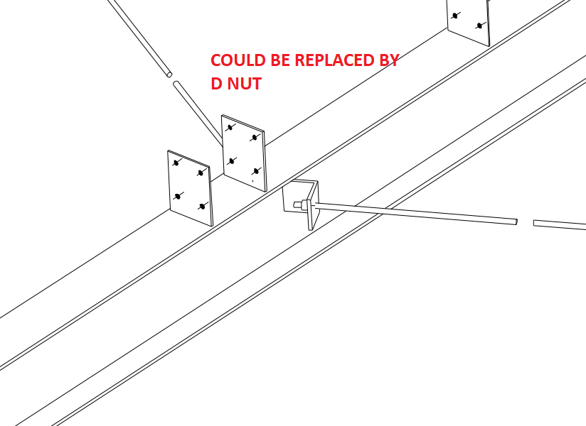
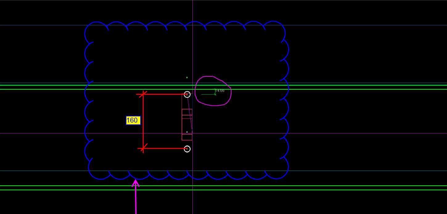
    The problem lies in the fact that the drawing calls for a cap plate. That is extremely problematic when you are using Decktite. The usual and preferred practice is to pull some Decktite over a pole and slide it down – much like pulling a T-shirt over your head.  You can think of the DeckTite as the T-shirt, and your head as a pole. The hole in the T-shirt fits snugly around your neck. But if you have a cap plate, the situation becomes different. In effect, to continue the analogy, having a cap plate is like expanding your head so that it is impossible large to be able to pull a T-shirt over it.  You simply cannot put on a t-shirt if your head is too large! The only way to wear the garment is to use a jacket, which can be split and wrapped around – which in this case means using a split Decktite. The problem with using split Decktite on corrugated roofing is that it doesn’t seal as well, and is cumbersome to install.

    In this case, you ought to confirm with the client how they want to handle this issue. If you bolt a cap plate on top of the column, then you are forced to use a split-Decktite. But if you want to weld on site, then you can use Decktite that is not split, and can largely avoid the complications of leaks occurring on the roof.


    Shows the issues which may crop up if the drawings is followed. You need to confirm these types of issues with the client.


  • Can you spot the problem – #1

    Attention detailers,

     Take a look at the following below and see if you can identify the issue/problem at hand. Take careful note of what I have marked up, and try to identify the issue.

    Spot the problem
    Consider the structural input drawing image as well, and see if you can spot the problems between the two.

    This is the second image – please do compare it with the structurals.


    Here are the structural drawings:

    Compare the structurals with the arch drawings to find the issue.
    Compare the structurals with the arch drawings to find the issue.

    Answer:

    There is an unsupported hebel panel here. Without support, the panel will surely break off. Therefore it needs a PL to support that panel, notwithstanding the engineer’s omission.

    This is the answer. You need to add a support for the Hebel panel.

    Take a look at the mark up above.

  • D NUT BRACING OR CLEAT BRACING?

    D NUT BRACING
    D NUT INSTALLATION ON A RAFTER

    A lot of fabricators prefer D Nut bracing over cleat bracing because it is much simpler and cheaper. If the engineer has specified cleat bracing the detailer must investigate whether a D Nut bracing will be sufficient. If yes, then please RFI the engineer with D Nut bracing proposal. The fabricator could prefer this connection. Make sure the maximum angles of the D Nut is observed


    BRACING
    BRACING AT RAFTER
  • Modeling Cage Bolts

    There is no need to spend a lot of time trying to model bolt cage accurately if the drawings can be annotated to get the final accurate final intent

    Here I am showing an example of a bolt cage. There is not need to model the helix to avoid the clash. No one can make a lig with clash. Physically impossible. So no need to model avoiding clash. Let it clash. When the fabricator makes the lig he will do it without clash.

    Also,

    https://youtu.be/8HsKLxGPBNc

    another point to note is that we need not model tight to the anchor rod. Let one side extend a little bit to avoid the radius riding into the anchor bolt. It will be easier for modeling and manufacturing. There is no compromise in the final intended outcome.

  • TRIM OR EXTEND GRID LINES IN ADVANCED STEEL

    This tutorial explains how to trim or extend grid lines in advanced steel.

    The is the last tutorial on basic grid lines. There are other advanced options like curved grid lines. But for the time being in a beginner course this is enough.

    If you can do this much confidently and correctly you will handle majority of the cases

  • Unequally spaced Grid Lines

    Here is video on how to create unequally spaced gridlines in Advanced steel

  • How to create a 4 line unidirection grid in Advance Steel

    This video explains how to create  a 4 line unidirectional grid in Advance Steel

    Please watch the video and practice it until you understand it. Any questions pls talk to me.

    https://youtu.be/oi6vDJaD1zk

  • advancesteel-Switch on tool palettes

    I struggled a bit on finding the tool palette and switch it on and off. But once you know it is a no brainer. Here is a video on how to switch on and off the tool palette in advance steel


  • Can it be built? Holes near the flange

    Erection Feasibility must always be considered when creating shop drawings. Consider the diagram below:

    Can you spot the problem with this drawing? This is meant to be a side-on view of a beam. The green lines represent the flanges of the beam. The white circles represent holes to be drilled. What is the problem here? Consider the distances highlighted.

    Pop-quiz: What is wrong with the above drawing?


    (Scroll down for the answers)


    (Scroll down for the answers)


    (Scroll down for the answers)


    The Answer:

    Drilling a hole so close to the flange is not easy, neither will it be easy to pass a rod through when it is so close to the flange. You only have 14 mm till the edge of the flange. What if you used the standard pitch of 160 by route – but you’ve also got to consider erection feasibility!

    Placing a hole so close to the flange will not work.