Please note that once we assign a job to the team members, the next step is to provide your ETA.
Whether our ETA is within or beyond the client’s expected date, it must be clearly updated in the status.
If the client decides to cancel the job due to late delivery, they will respond to the status, and Ben will inform us.
If there are any RFIs in the received documents, they must be raised immediately, and the status should be updated as “RFI raised on [date]” & “xxx days required to deliver the take-off reports.”
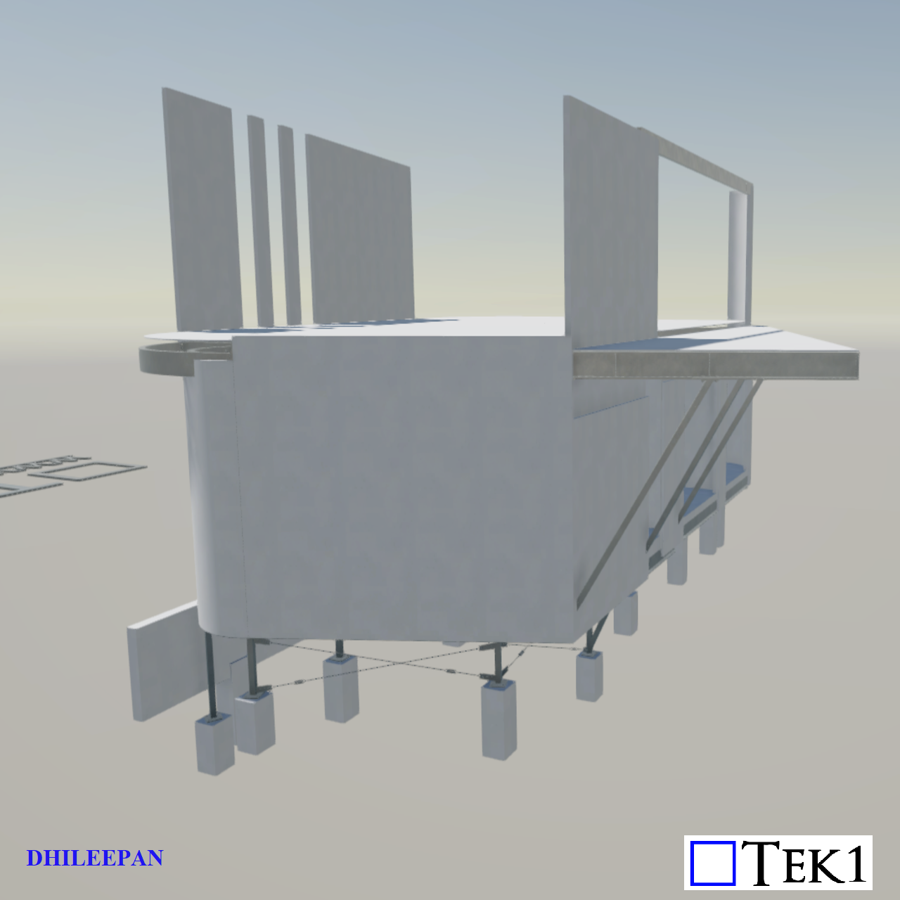
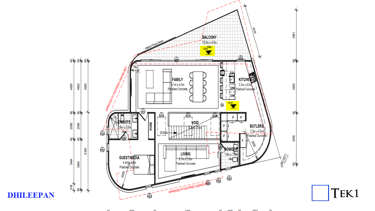
In a residential project nestled in the scenic suburb of Scarborough, Bundeena, a critical coordination issue surfaced during the construction of the first-floor balcony. Originally designed to sit 100mm lower than the internal first-floor level (with the balcony at RL+33.000 and the floor level inside the residence at RL+33.100), the structural drawings, however, did not reflect this intended step-down.
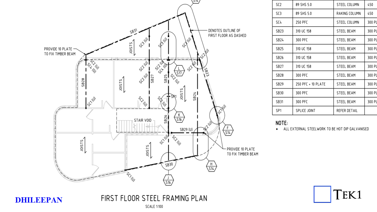
ARCHITECTURAL PLANSTRUCTURAL PLAN
Floor Depth Conflict
Adding to the complexity, the vertical space between the first-floor Finished Floor Level (FFL) and the ground floor Ceiling Level (FCL) was only 300mm, while the structural floor members specified were 327mm deep. This created an unintended exposure of the first-floor framing—both below the ceiling and above the balcony floor.
Level Adjustment Solution
Upon identifying the discrepancy, Tek1 promptly flagged the issue to both the structural engineer and the architect. A collaborative resolution was achieved by adjusting the levels: the internal FFL was raised to RL+33.253 and the balcony FFL to RL+33.153, restoring the 100mm step-down while maintaining all ground floor steel members at their original elevations. The level variation was managed by introducing floor joists of different depths—an efficient solution that avoided reworking the base structure.
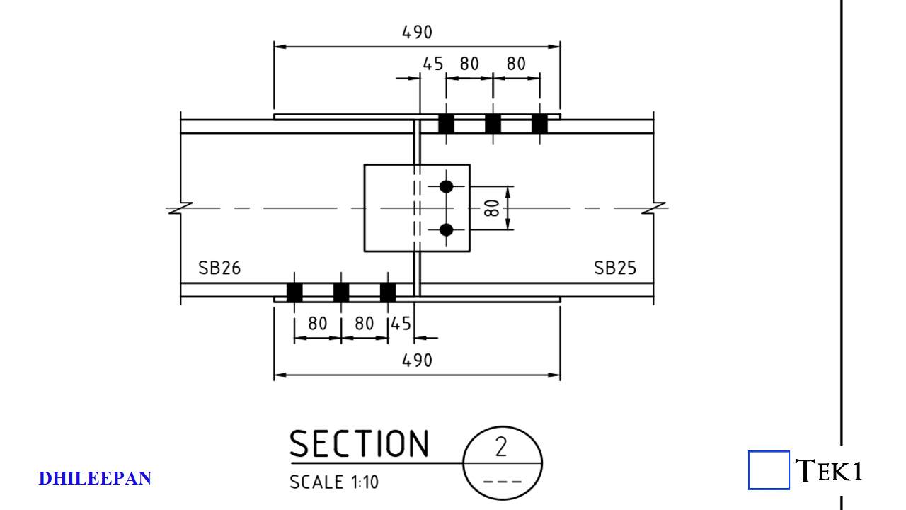
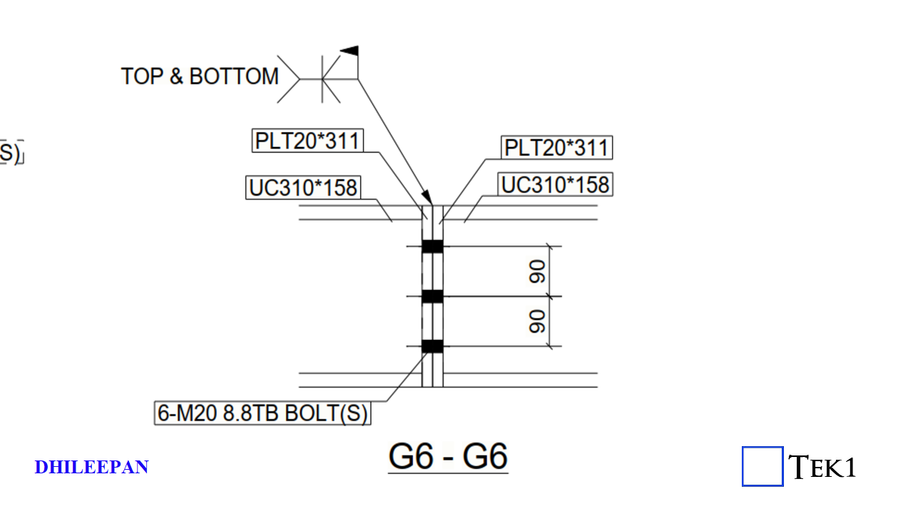
Splice Connection Clash
Another issue surfaced in the form of a splice connection detail provided in the structural drawings. The original design called for splice plates on both the top and bottom flanges of the beam. However, the bottom plate posed a risk of clashing with the ceiling board. Tek1 proactively suggested an alternative splice configuration that avoided interference with the ceiling. This revised detail was reviewed and subsequently approved by the structural engineer.
DESIGN SPLICEPRPOPOSED SPLICE
Conclusion
This case serves as a strong example of how early-stage detection, open communication, and thoughtful coordination between teams can lead to efficient, buildable solutions—ensuring design intent is met without compromising on functionality or aesthetics.
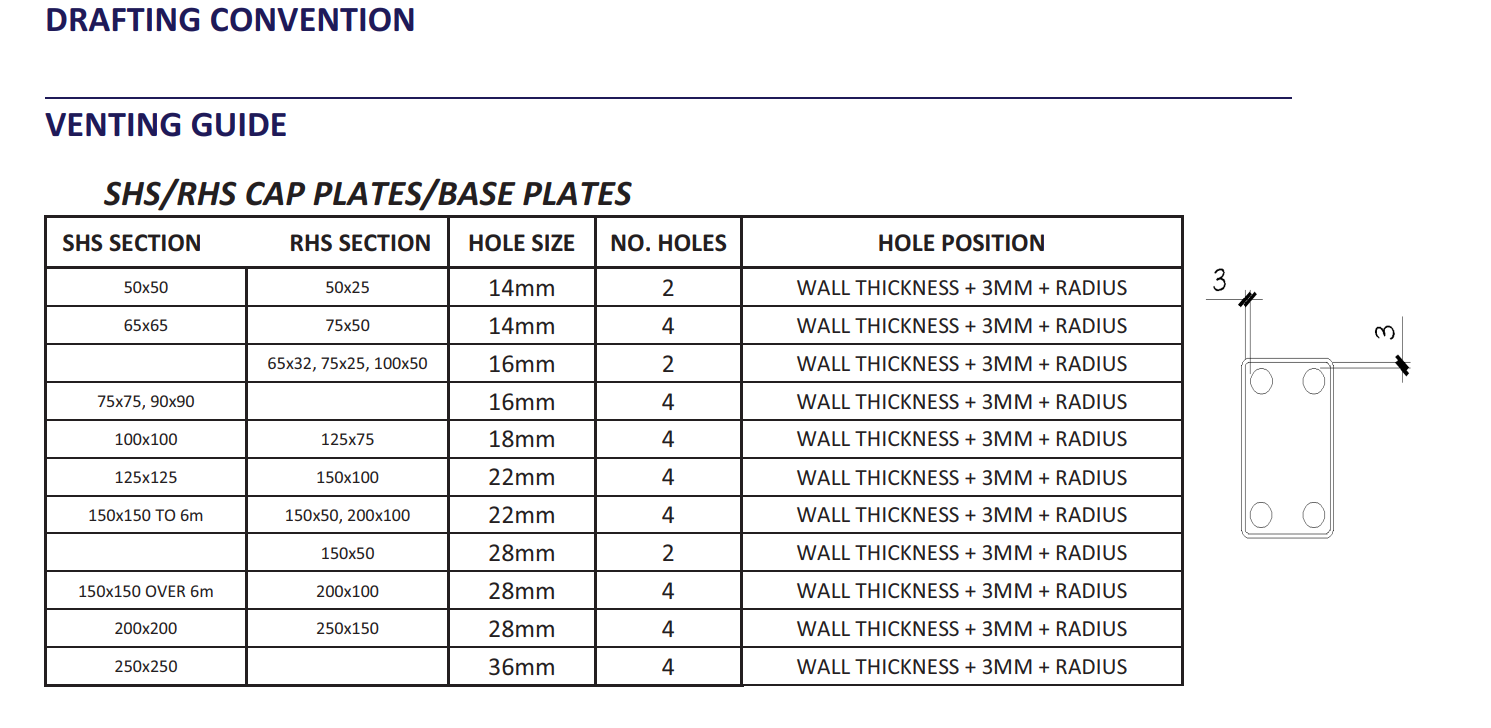
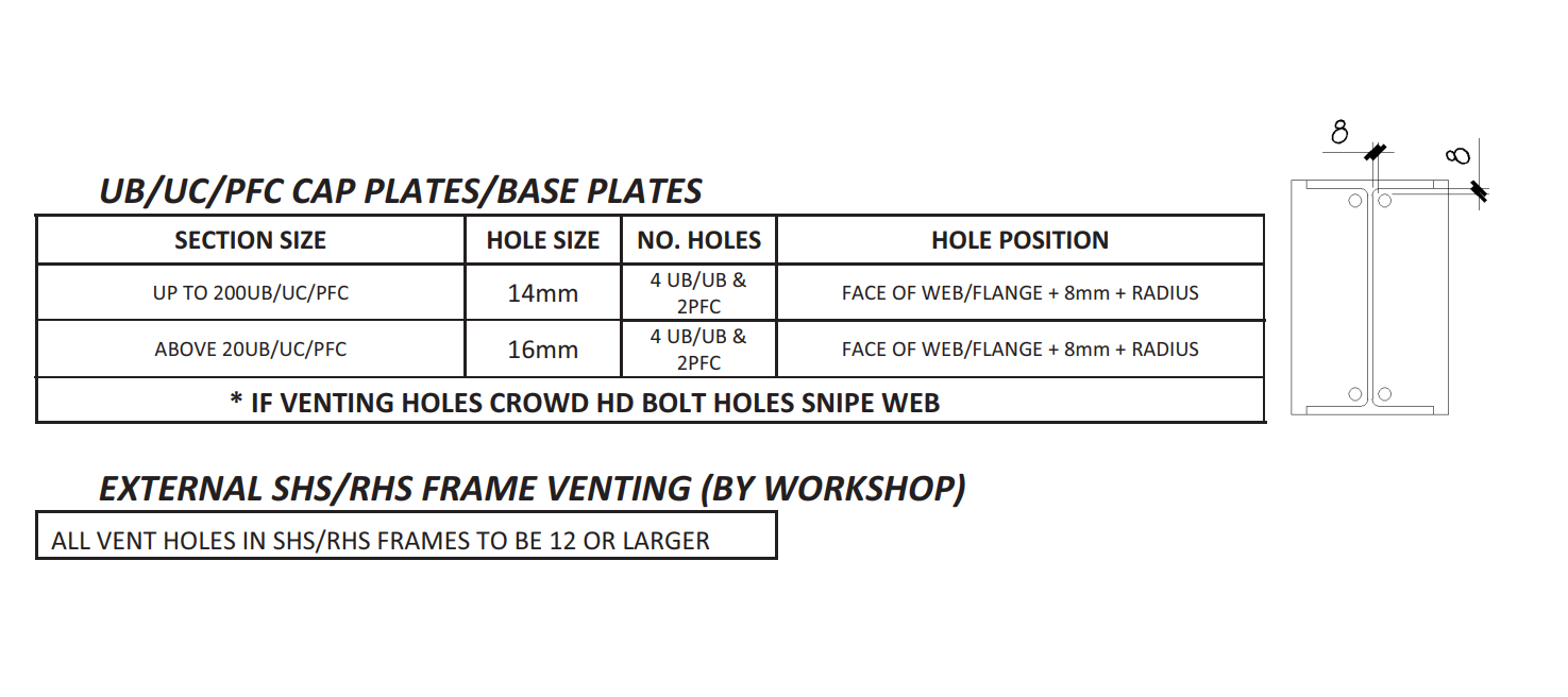
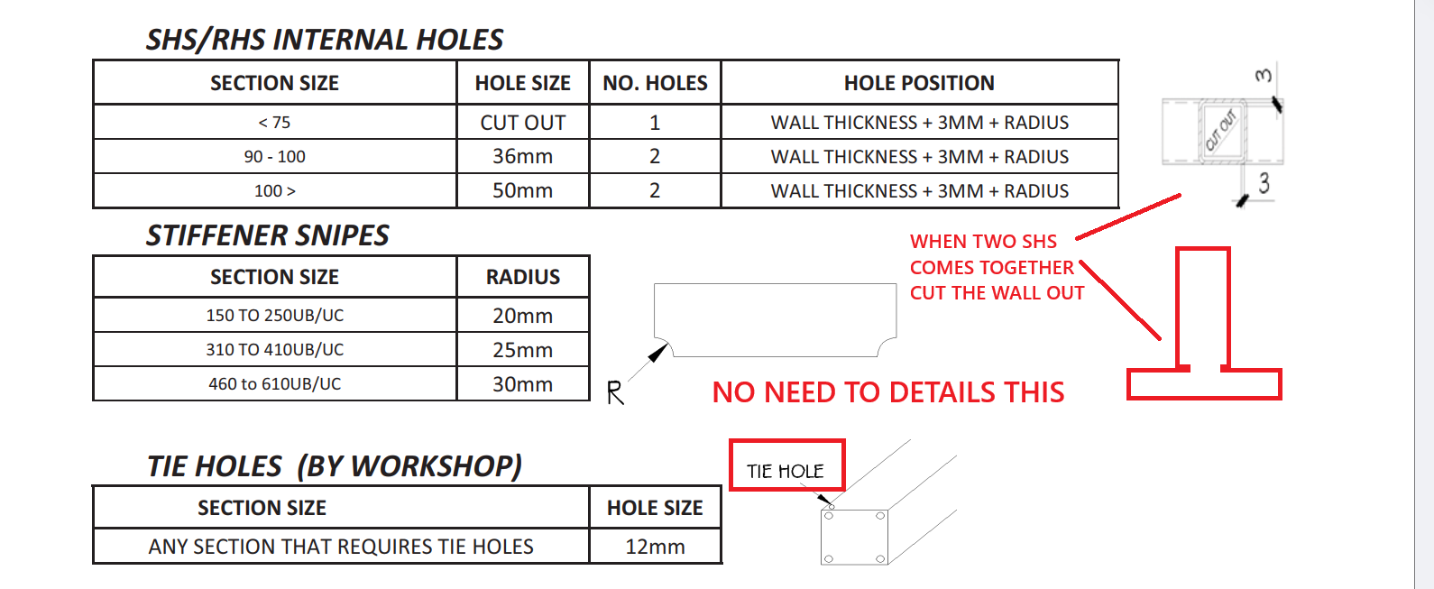
Note: you will need to prepare steel in order to galvanise. This may involve adding holes to the steel, in order explosions in the galvanising bath, so that air can always escape.
What is primer?
It is a coating you apply to steel, in order to help paint stick on to it. It can also have some durability benefits e.g. preventing corrosion.
You must follow the finish notes listed in Engineer and Architectural drawings.
If the steel is exposed to the elements, it will usually be specified as Hot Dip Galvanized (HDG). For interior structural steel, a primer coating is typically applied. And perhaps, where required, a top coat finish will be applied to make it look aesthetically pleasing.
What happens if you ignore or avoid finishes?
Rework & Labor Costs: Mistakes in applying paint, primer, or epoxy can lead to complete rectivication works. HDG requires a lead time and is particularly expensive.
Increased Maintenance: with poorly applied finishes.
Structural Damage Repair: with mis-specified finishes.
Legal and Warranty Implications: You could lose insurance.
Financial Impact: Could be significant.
What is the lesson learned?
When steel detailing, it is critical that you look carefully at the finishes of steel.
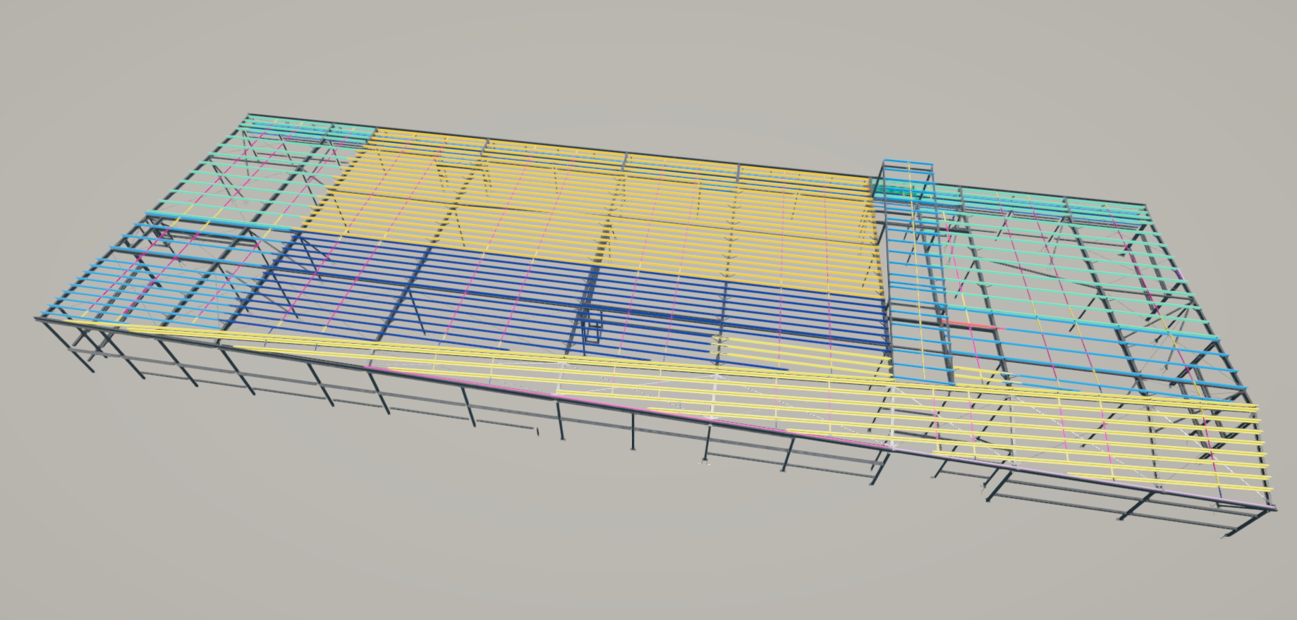
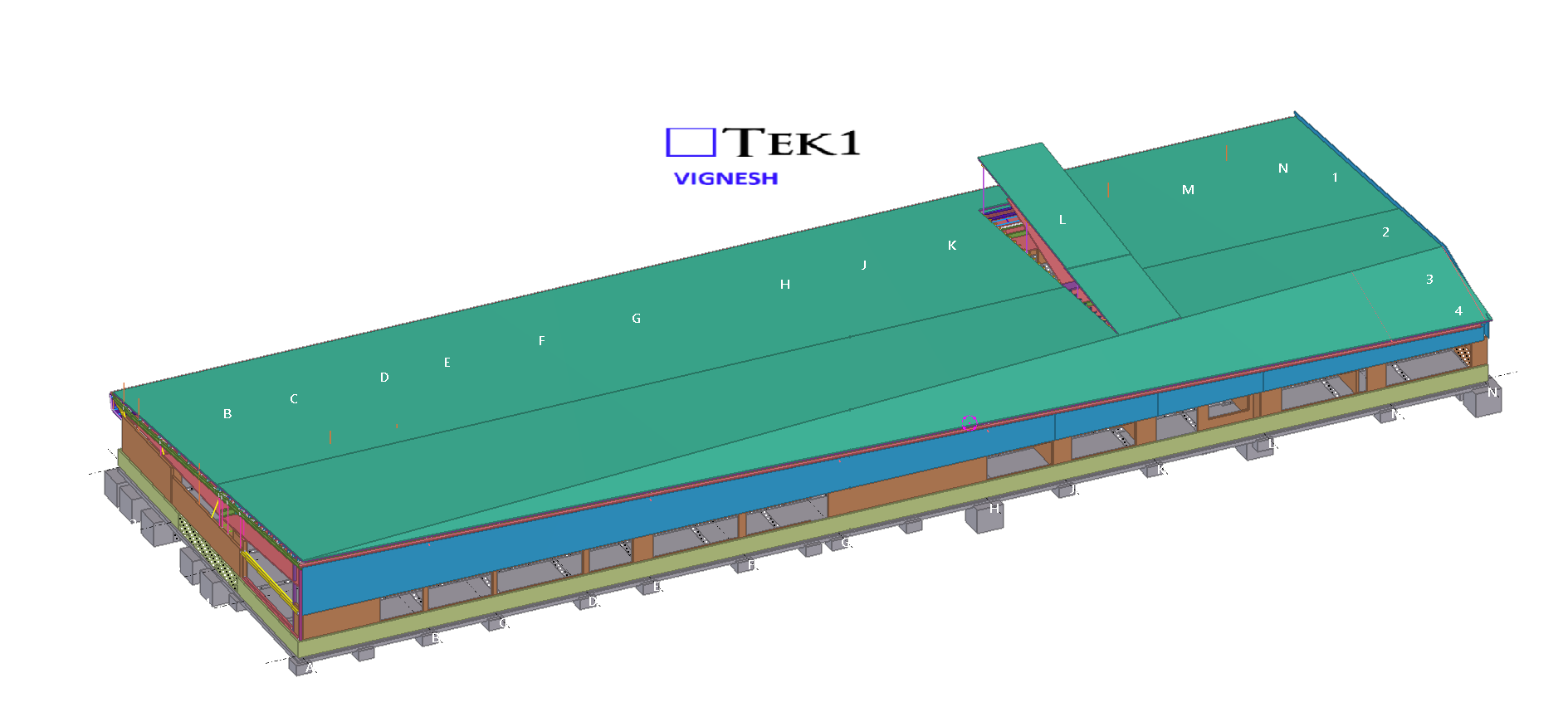
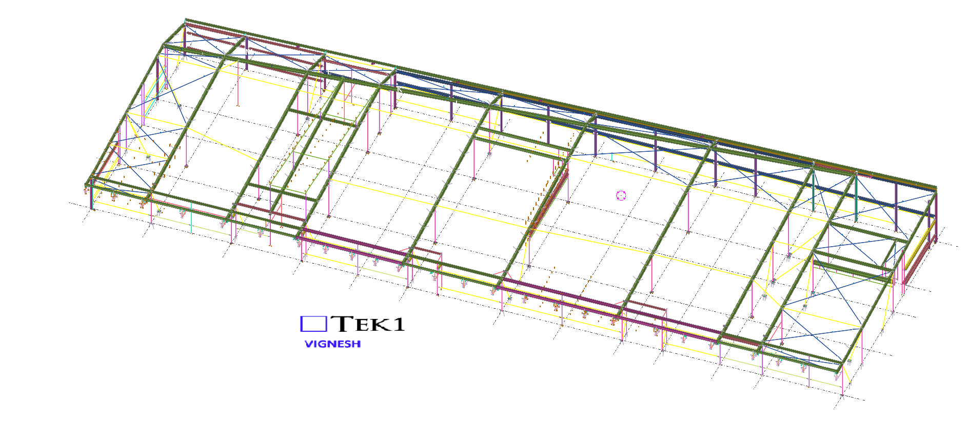
We are proud to be a part of the team in VSBA School-51 project.
Our detailing team worked closely with architects to ensure tolerances and offsets were met without compromising design intent With a limited fabrication and erection window, our detailing team adopted a fast-track workflow using Tekla Structures for 3D modeling.
This allowed us to provide early shop drawings for procurement and parallel review of sections still under coordination.
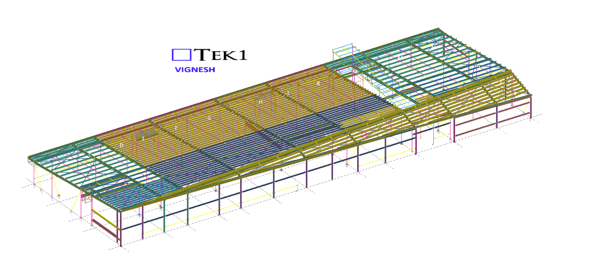
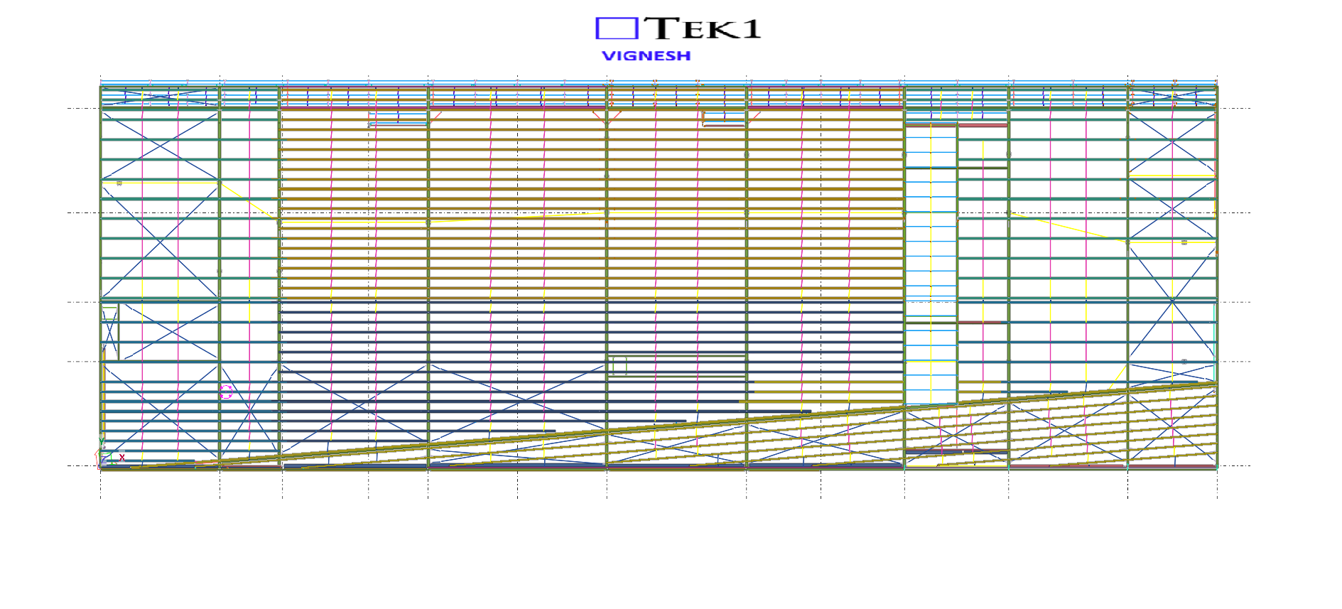
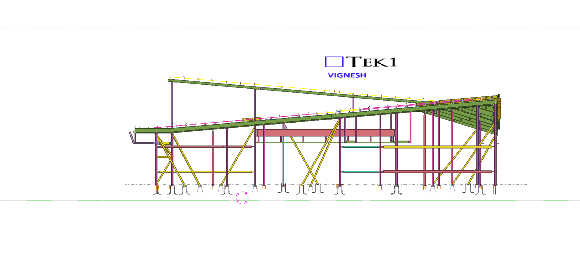
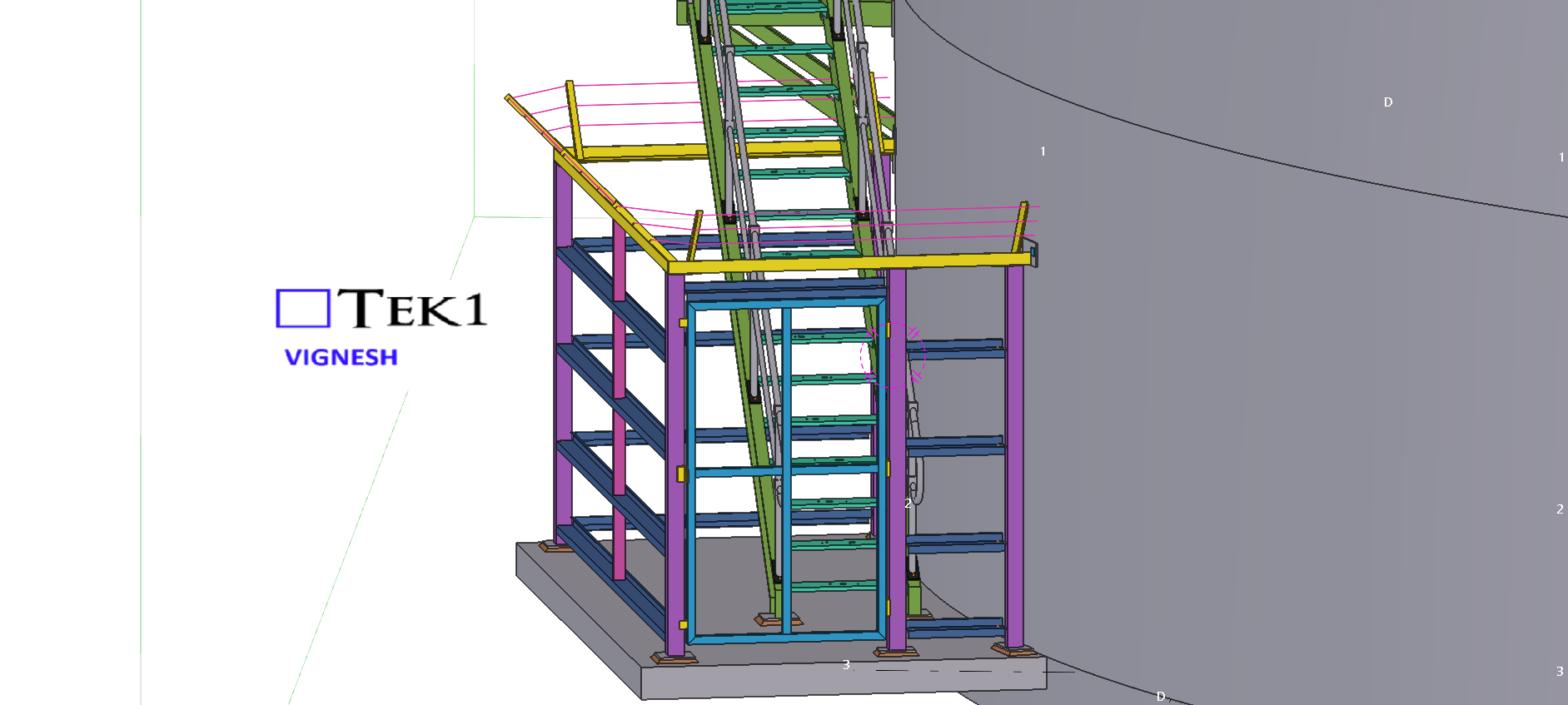
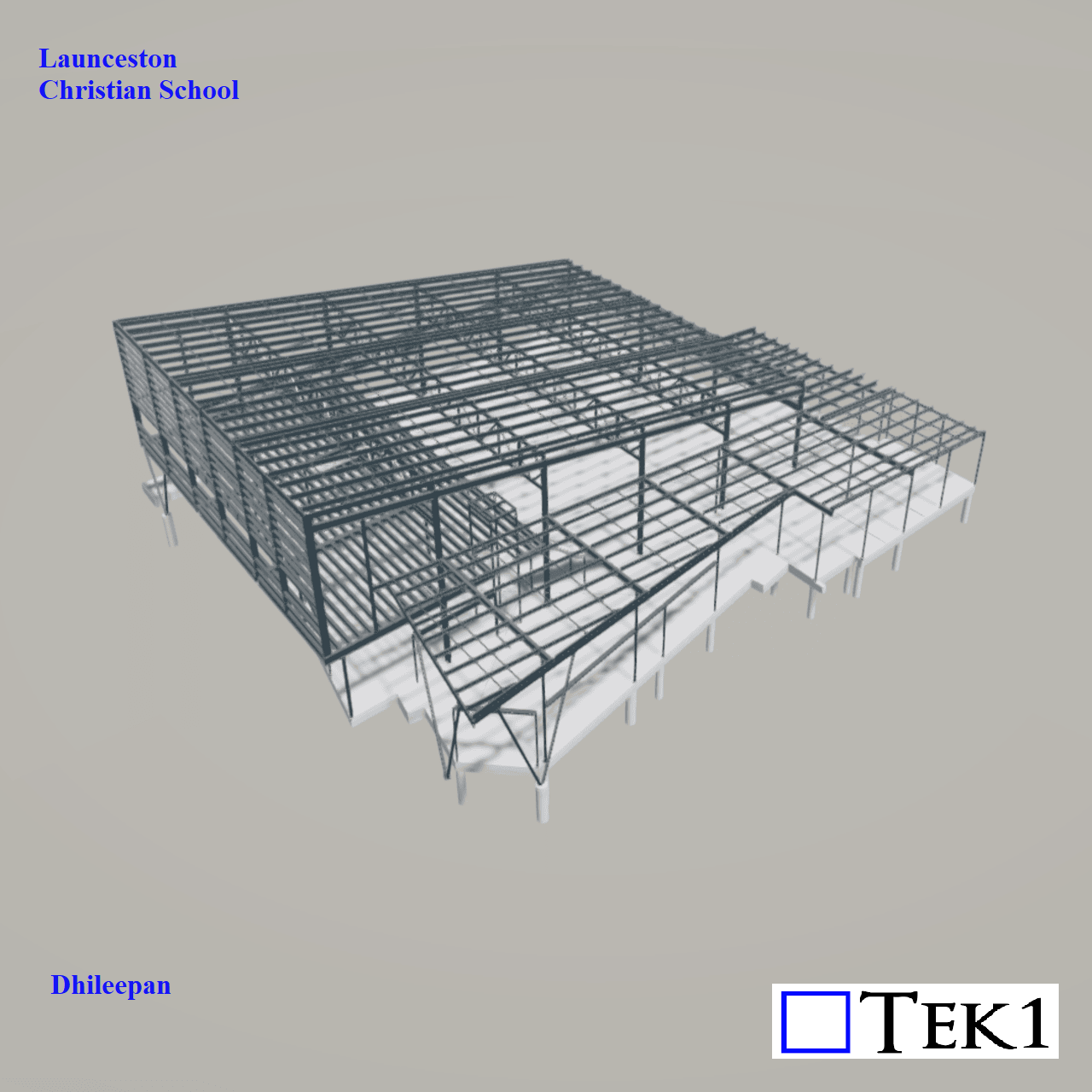
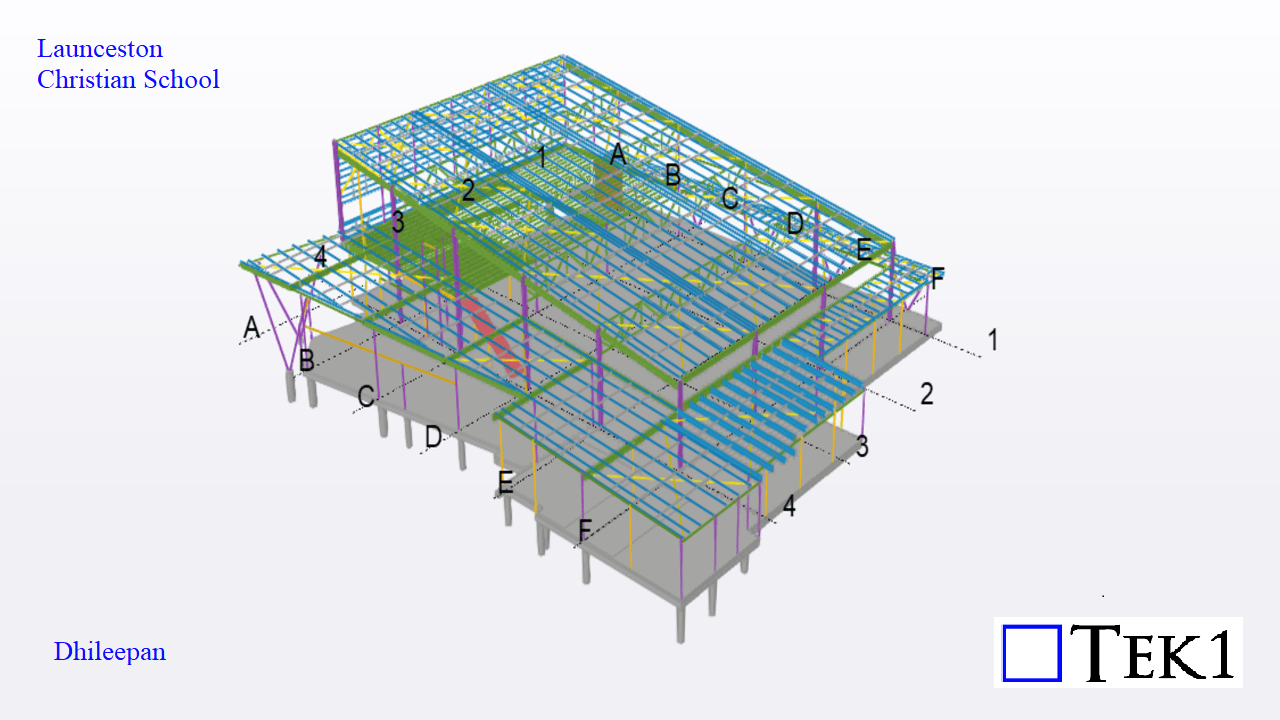
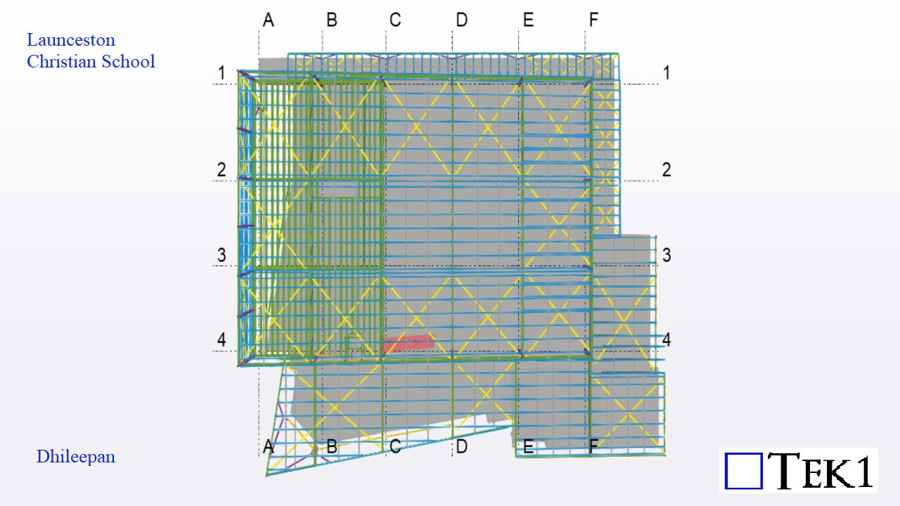
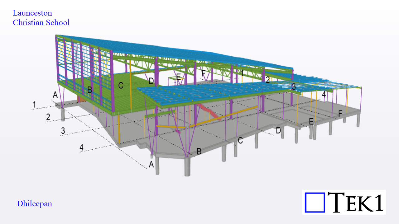
Let’s dive into the exciting expansion at Launceston Christian School in Tasmania—a thoughtfully designed new building covering an area of 1,440 square meters. This structure adds essential facilities to the campus, including classrooms, an auditorium, a storage room, and a library.
Challenges:
A key engineering challenge in this project was related to the cast-in base plates. These base plates had to be finalized and fabricated before the slab pour could begin. This required us to release accurate base plate fabrication drawings and exact location details early in the project timeline.
Since altering column positions later would not be feasible—especially if rafter alignments or other components demanded changes—we had to finalize all column locations at the earliest stage. This meant that the column modeling had to be both precise and quick.
Once the column layout was locked in, the modeling of the beams and girts progressed smoothly without any complications.
This project serves as a great example of how early coordination, clarity in design, and proactive decision-making contribute to successful structural outcomes.
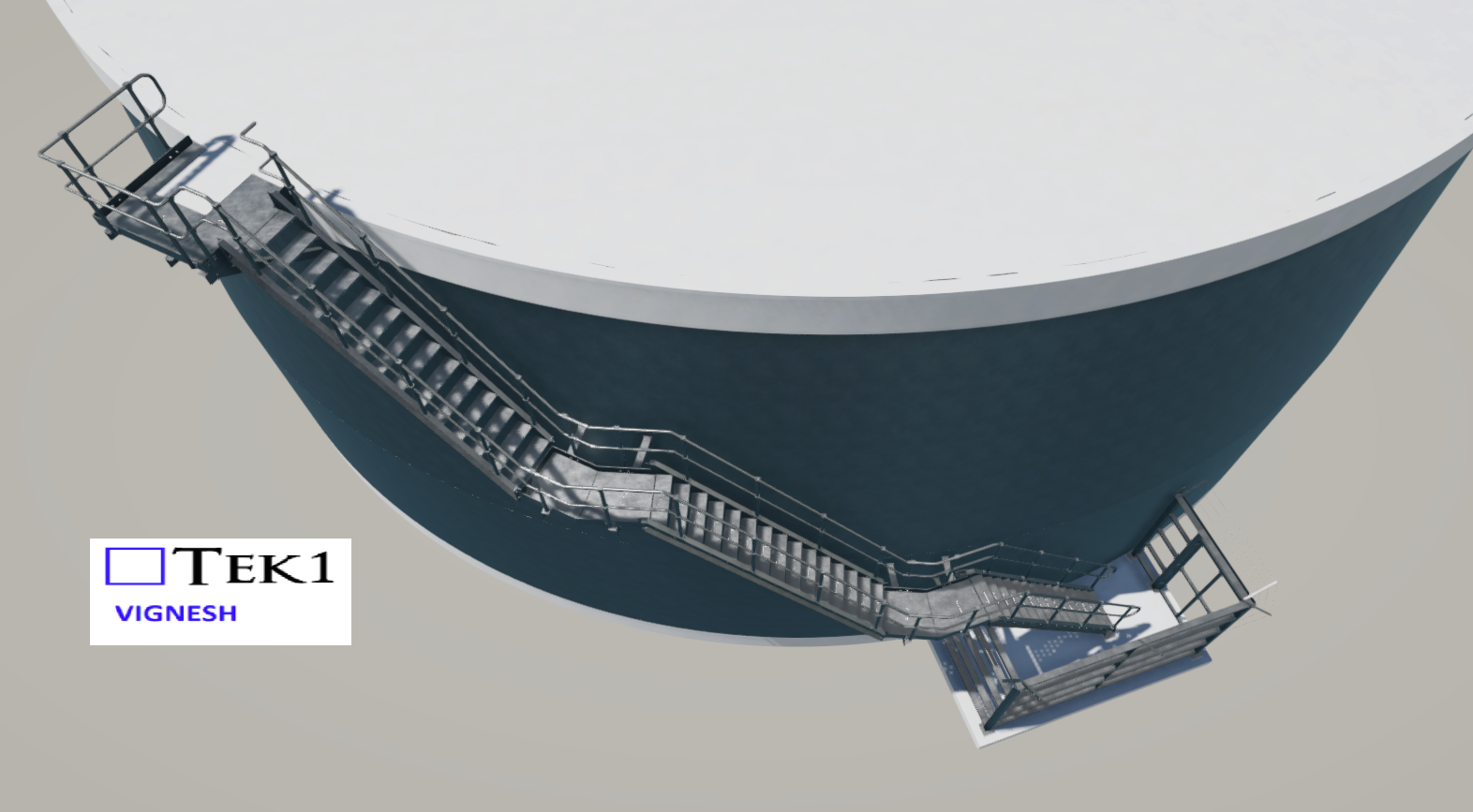
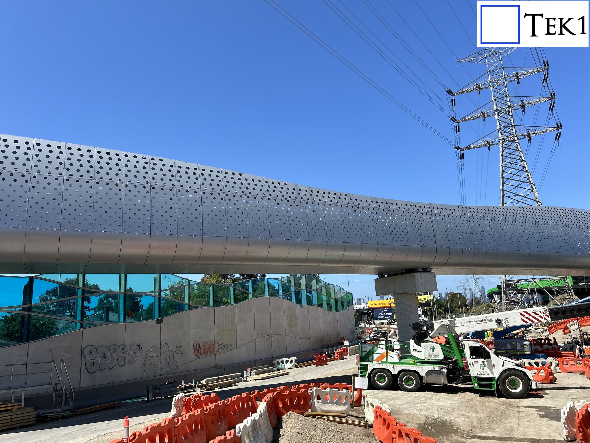
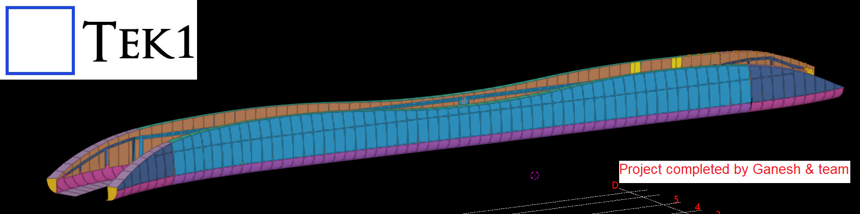
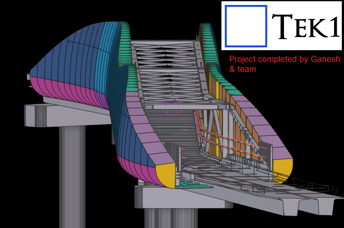
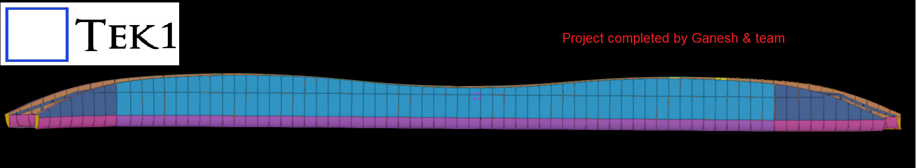
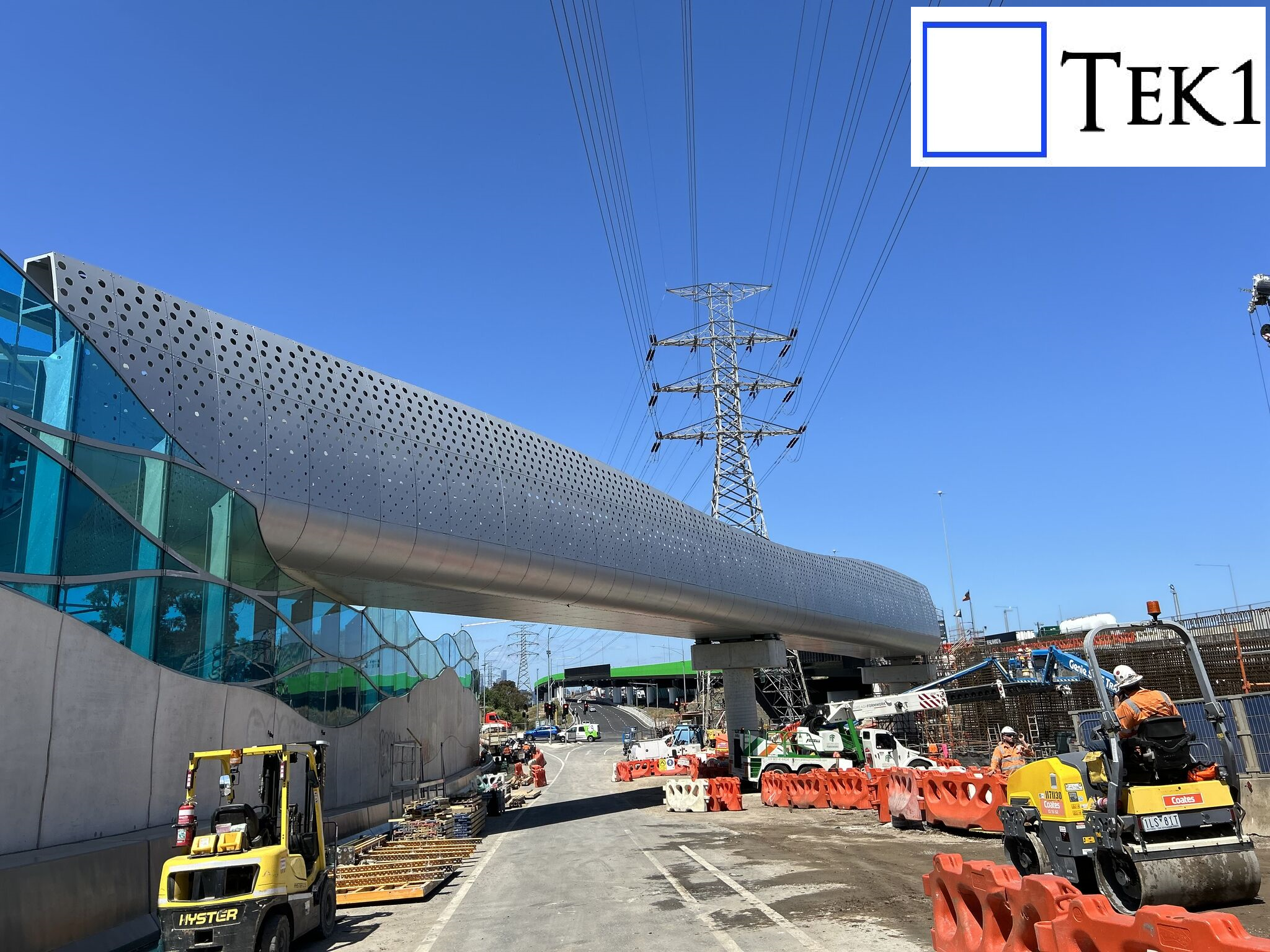
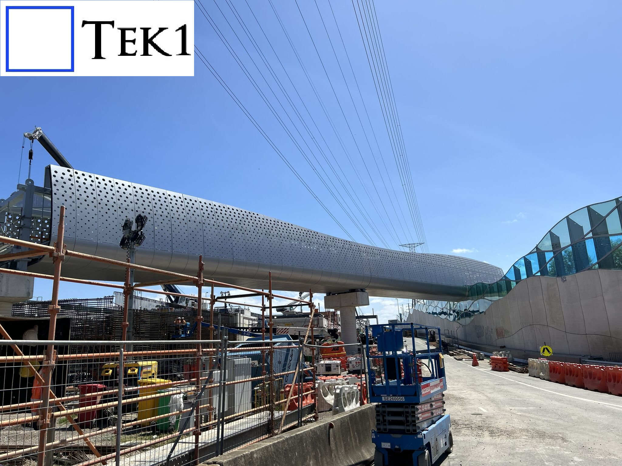
Tek1 recently completed a cladding project for a prominent organization in Australia. The project involved detailing cladding and its support system around a footbridge with unique challenges.
The footbridge featured curved ends, but these were not simple linear curves, making the design and detailing process particularly intricate.
Tek1 conducted numerous meetings with the client and engineers to finalize the cladding’s shape and ensure it met both aesthetic and structural requirements. This collaborative approach ensured the project’s success.