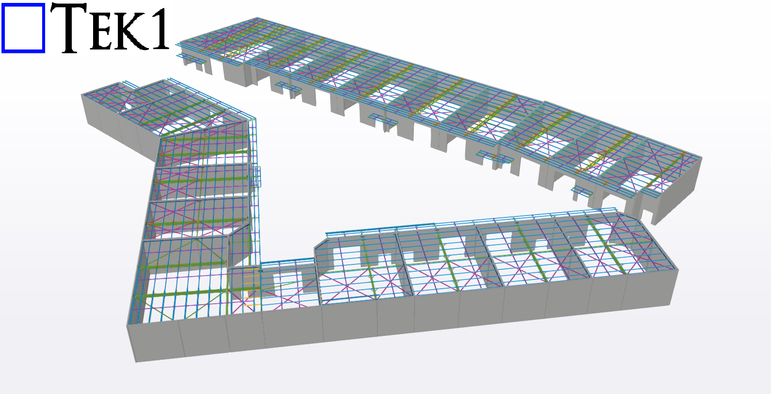
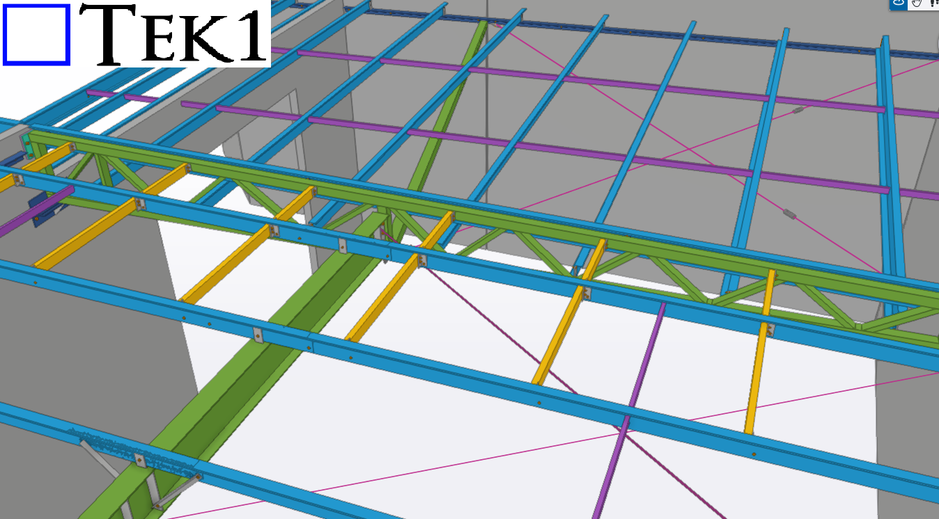
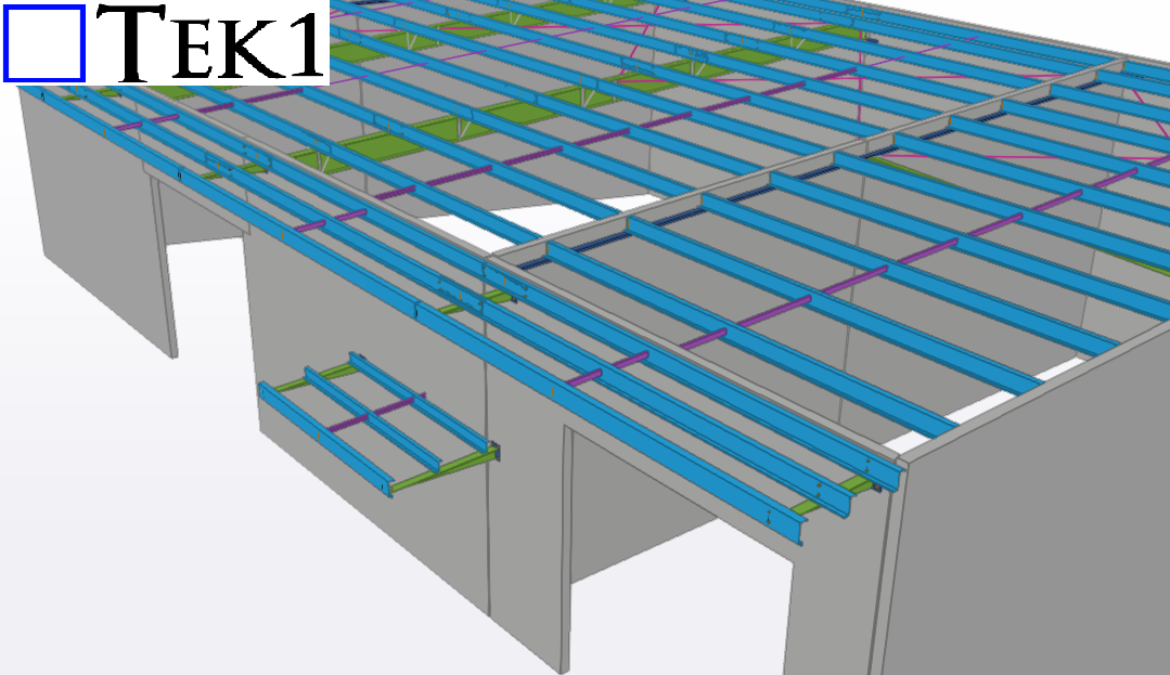
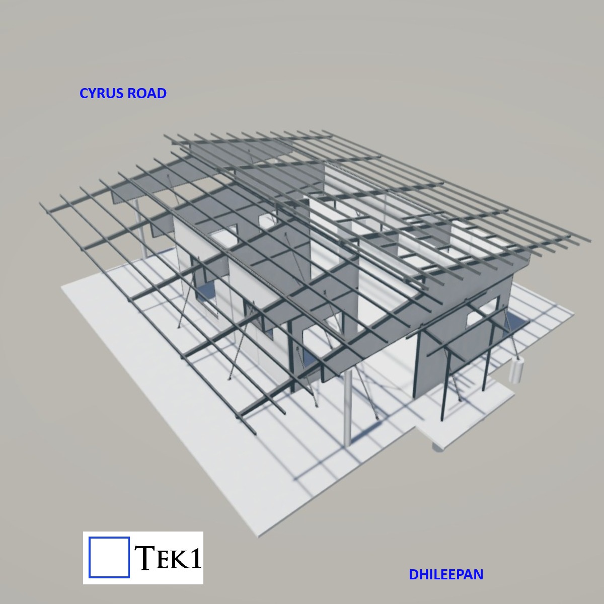
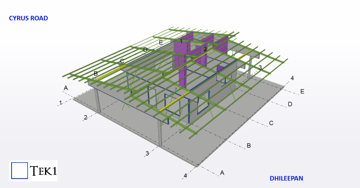
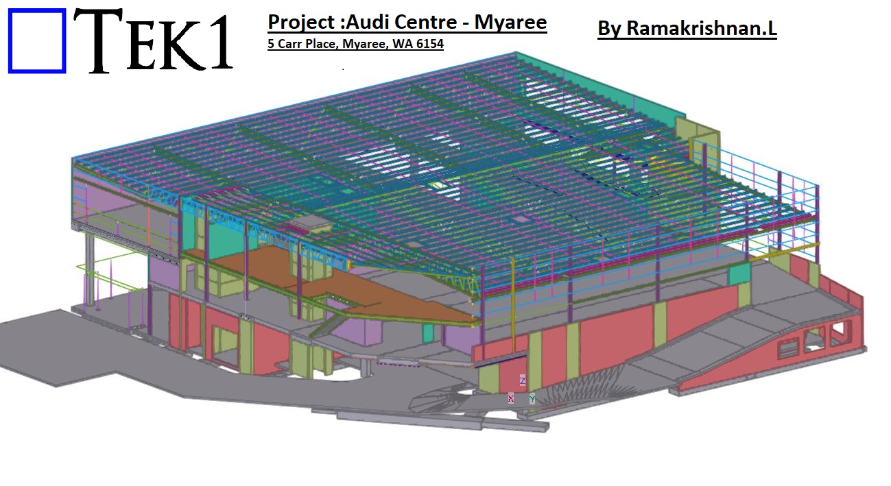
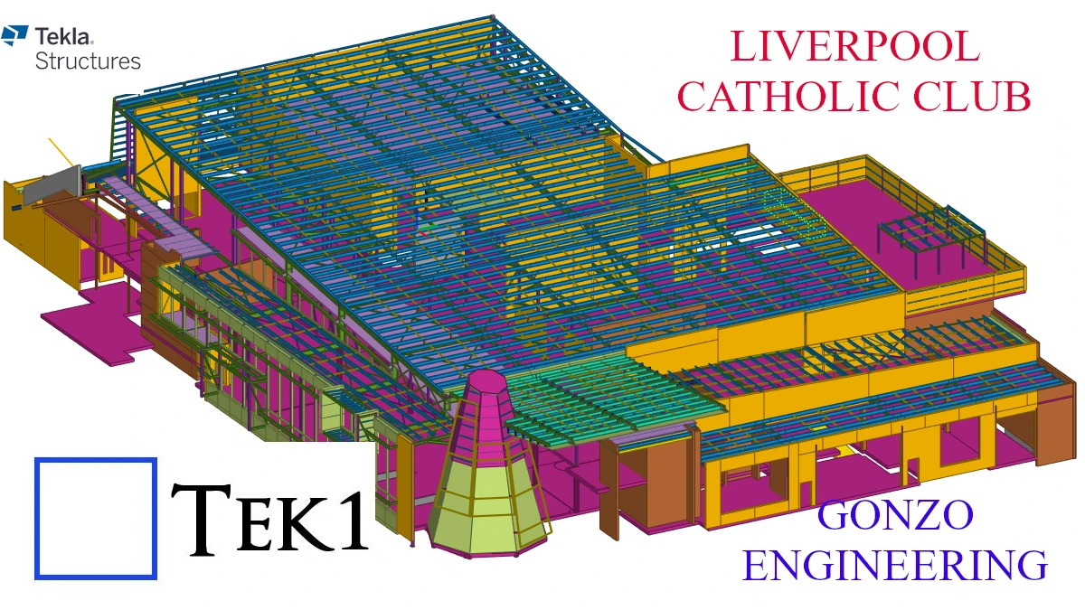
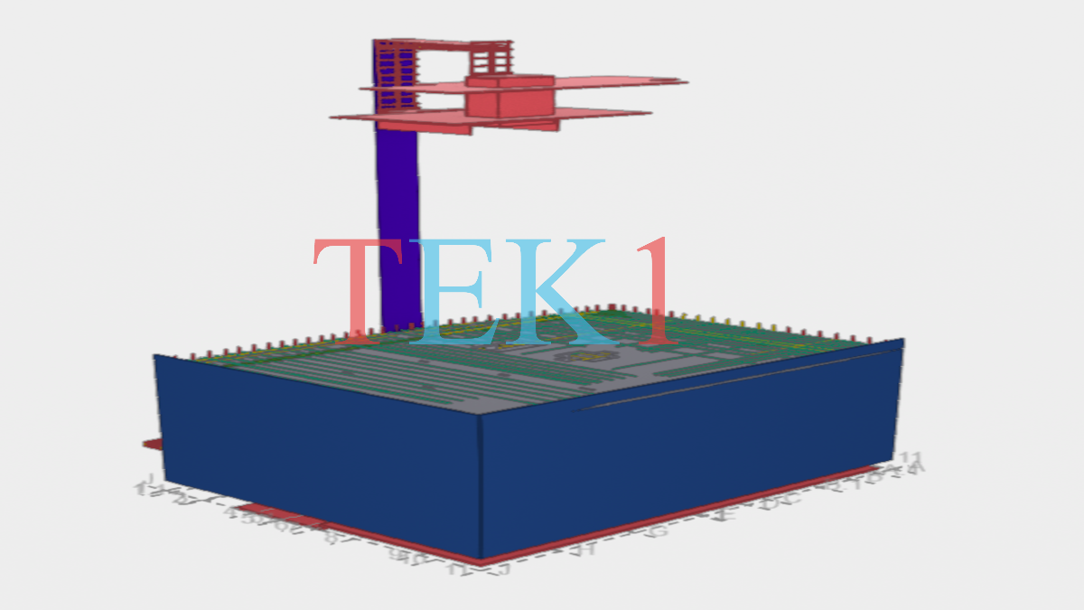
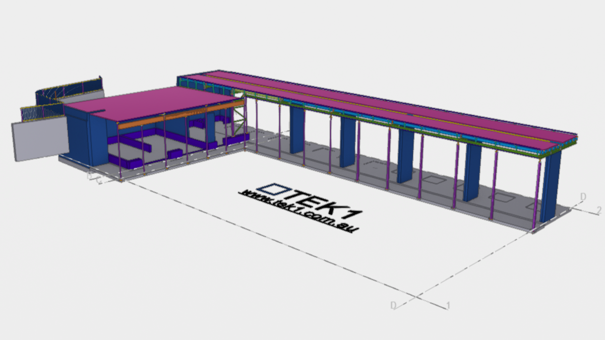
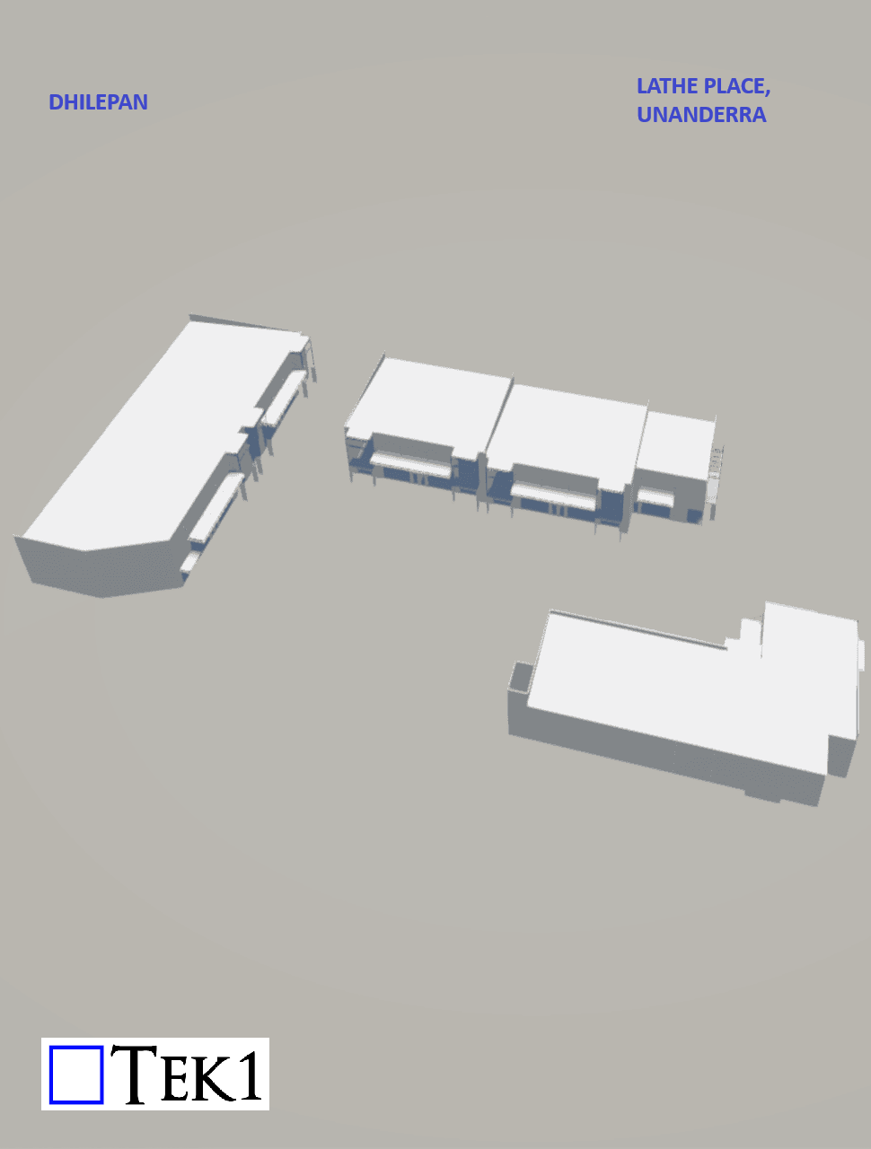
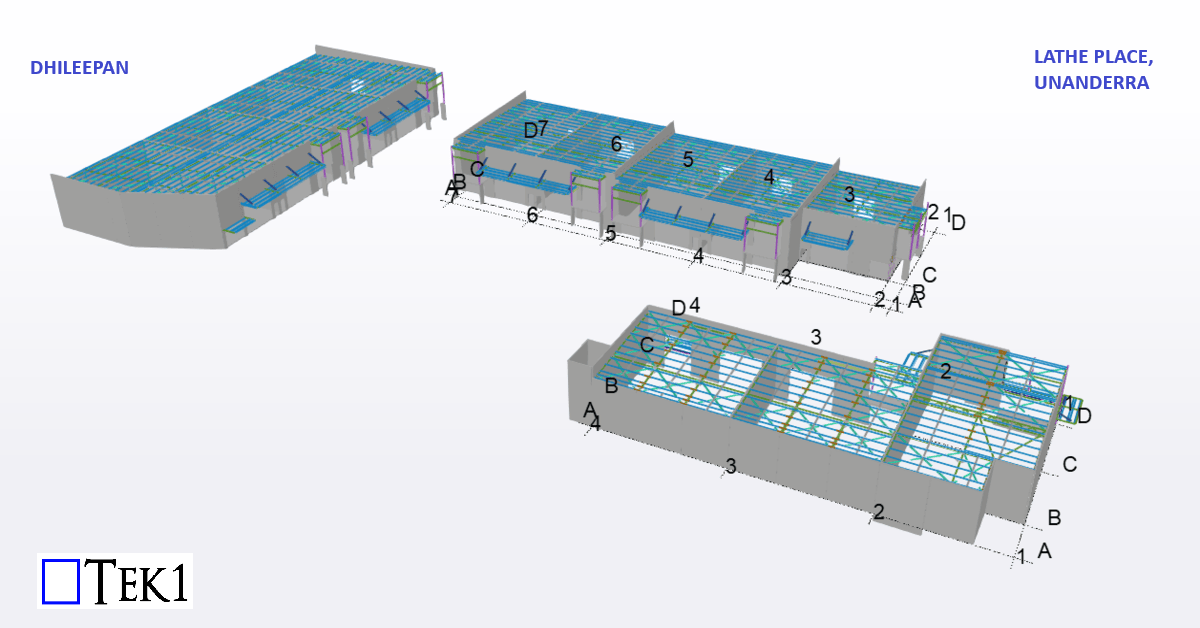
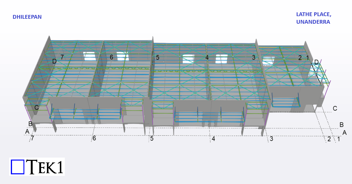
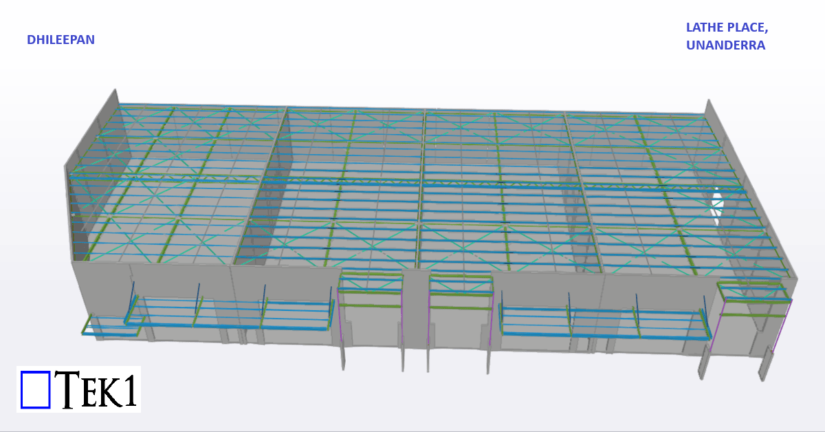
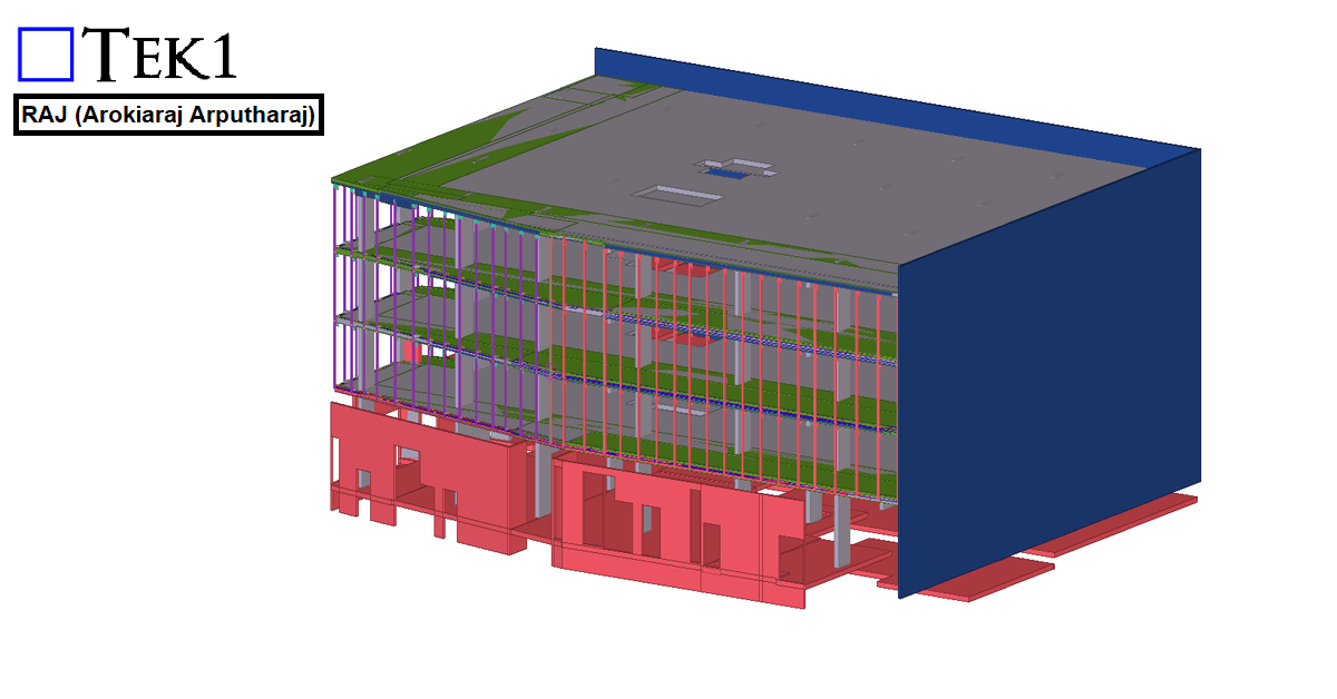
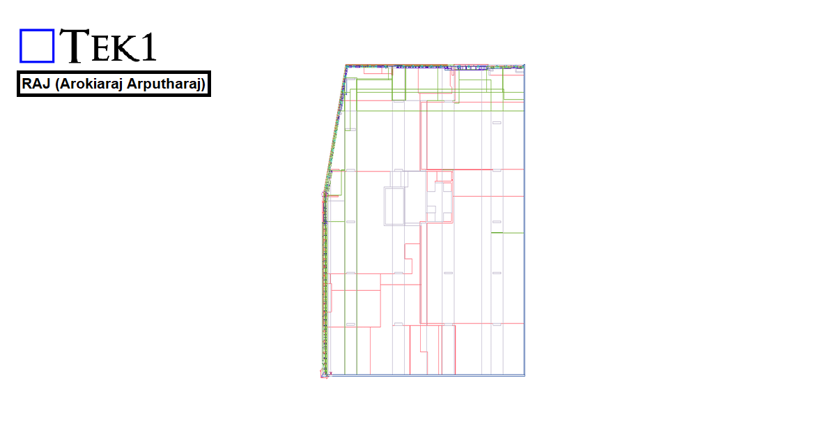
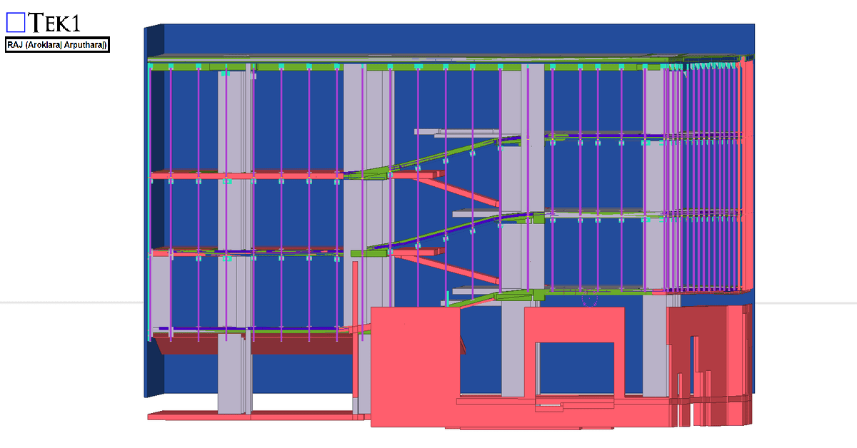
TEK1 completed a residential project for a prominent organization in Australia. Our primary scope was to provide the detailing drawings for the industrial units.
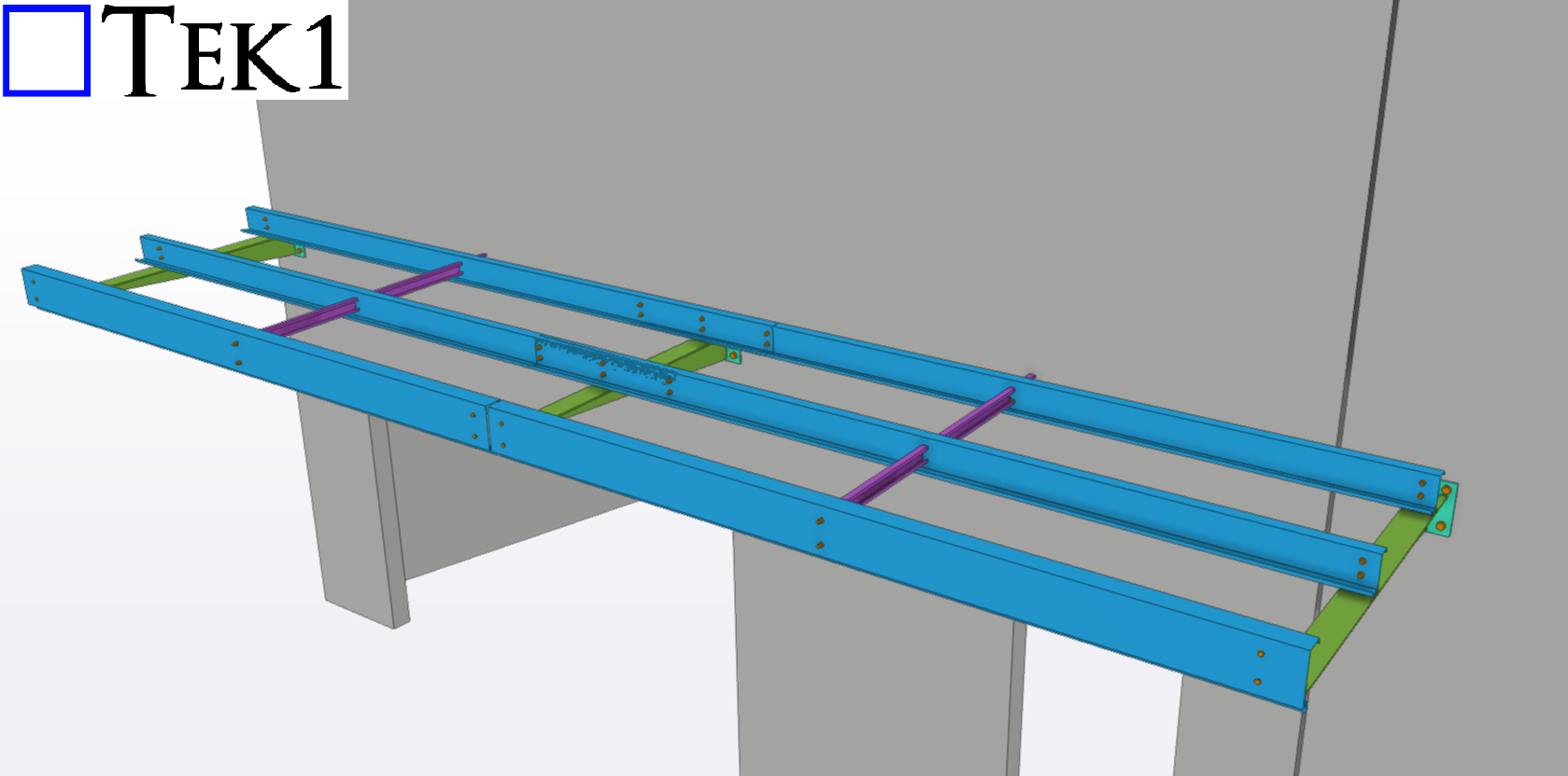
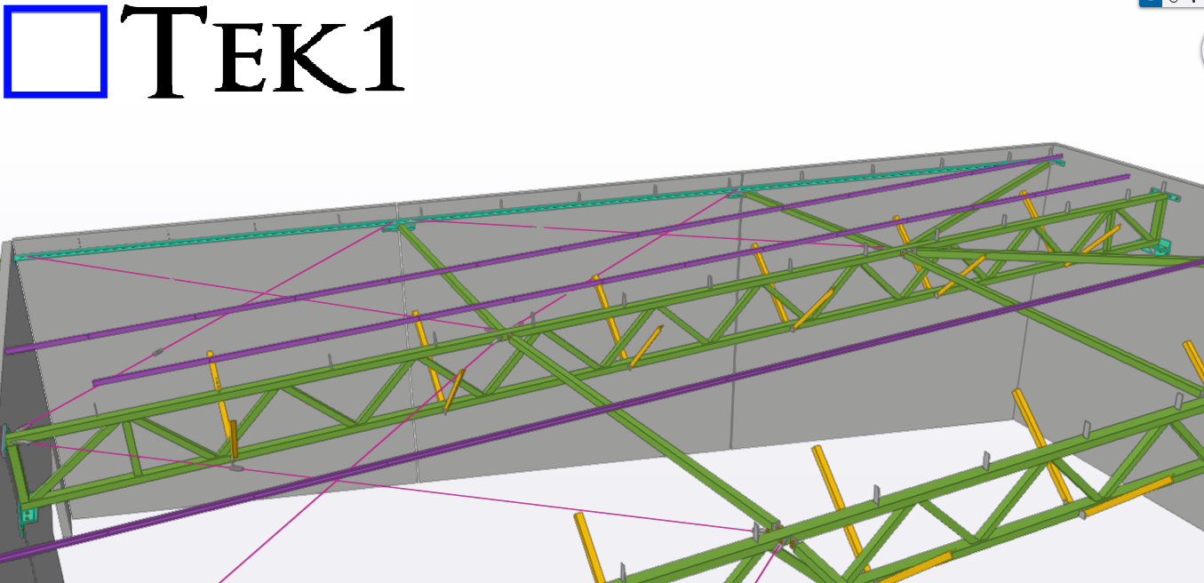
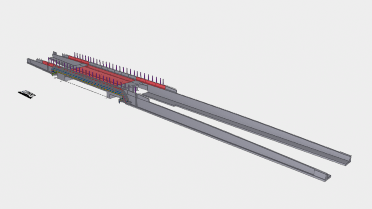
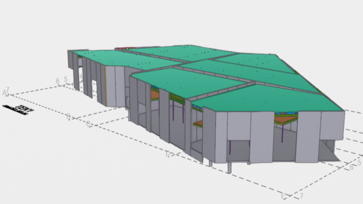
The project required close coordination with the precast detailer, as all the roof steel was supported by precast walls rather than conventional steel columns. This made accurate coordination critical to ensure all connections aligned correctly.
To achieve this, we conducted numerous coordination meetings with the client and the precast team, helping the project progress smoothly and minimizing the risk of site issues and rework.
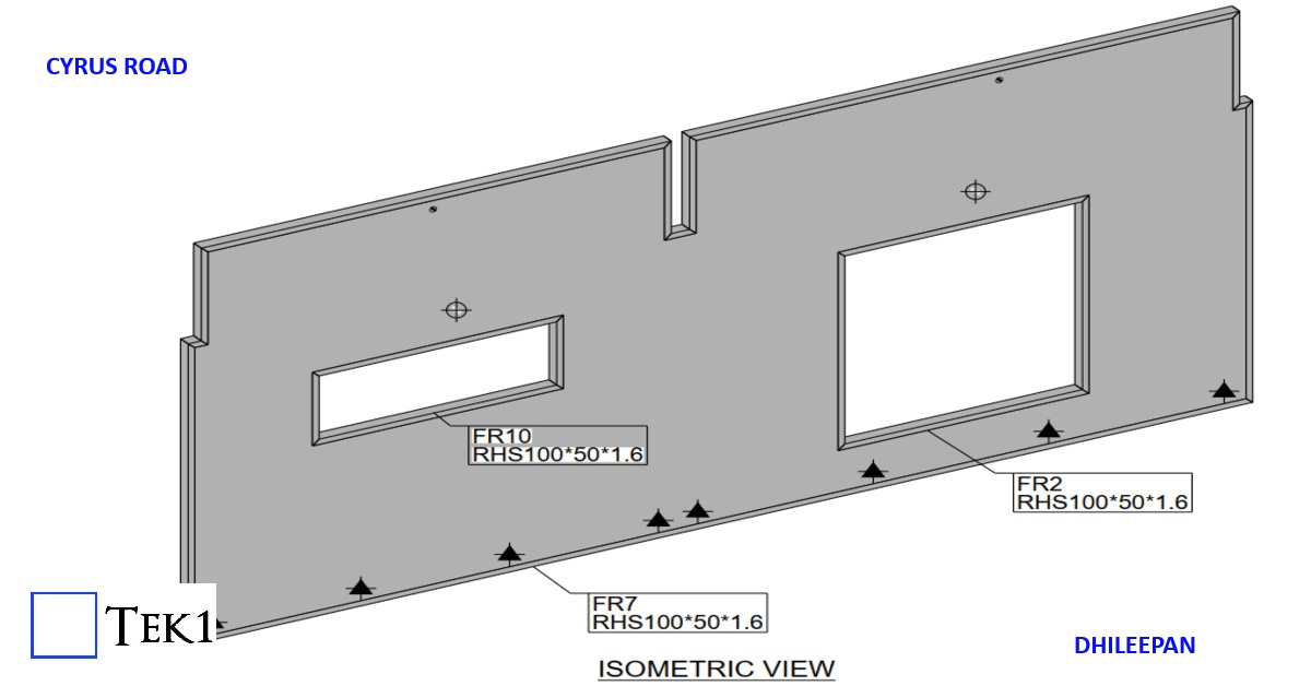
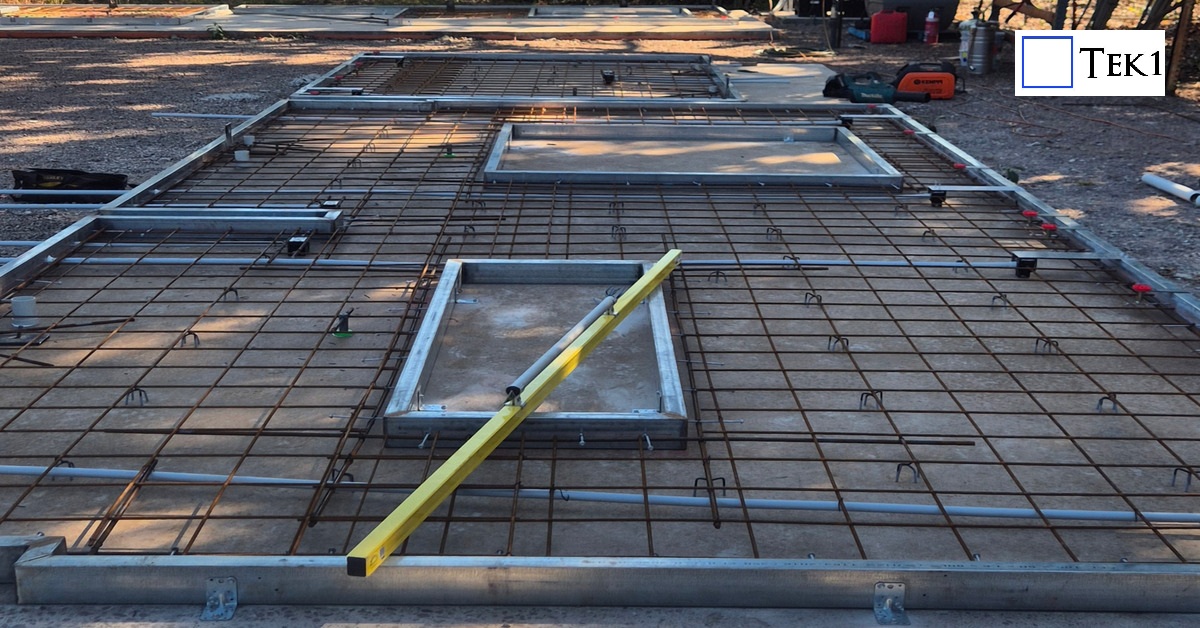
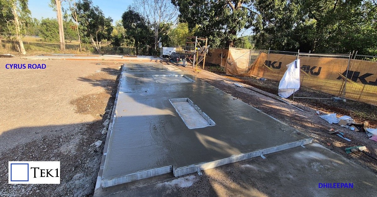
This residential project showcases an innovative hybrid construction approach, where the entire building is formed using just 11 precast composite panels and a few stud walls. Each panel consists of a fabricated steel perimeter frame filled with cast concrete, creating a strong, integrated structural unit. On site, the panels are positioned and welded together through their steel edges, forming a rigid, continuous structure.
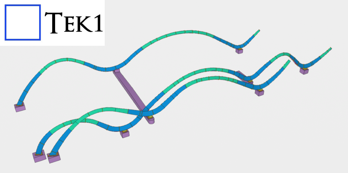
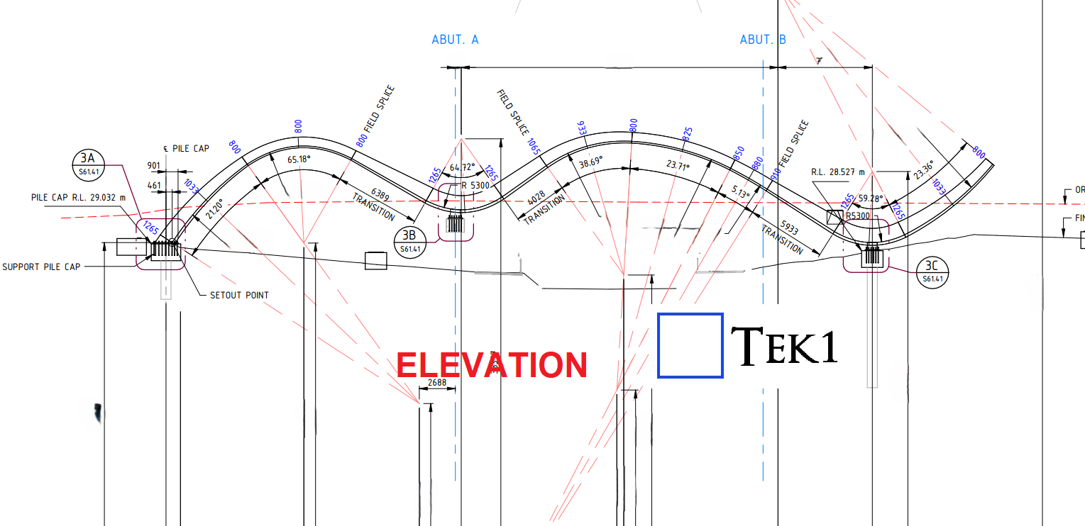
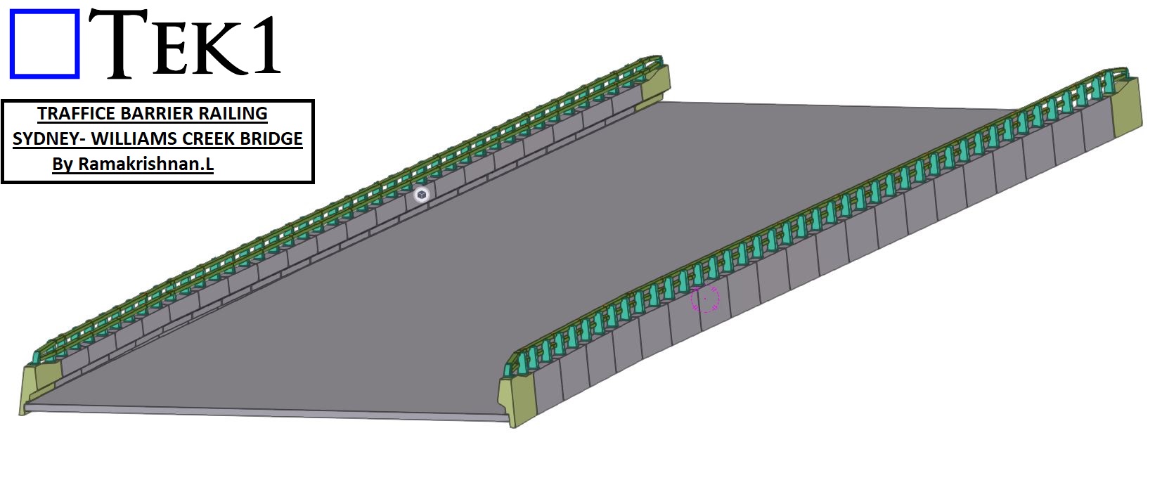
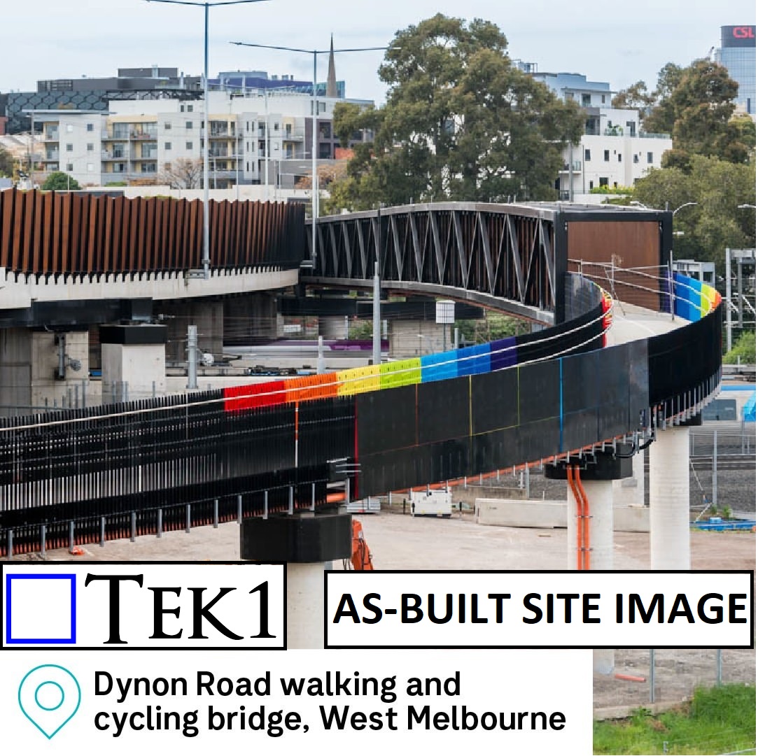
Recently, we were awarded a project to detail a curved section on the bridge for a reputed organization in Australia. The geometry involved presented some unique challenges.
From the elevation, the structure followed a non-linear zig-zag curvature, creating a dynamic and aesthetically driven form.
In this blog, we will look at how to create and share new materials in a Tekla model. By default, Tekla comes with a predefined list of materials stored in the system drive (C drive). However, in many projects, we often need to add custom materials based on project requirements. To add a new material, go to the Menu at the top left corner, navigate to Catalogs, and then open the Material Catalog. From there, select an existing material, right click & selct “Add Grade,” rename it as required, and assign the appropriate density. Once saved, the new material will be available in the model.
When sharing the model, especially using the db1 file to reduce file size, the newly added materials may not be available to the recipient. This is because custom materials are stored separately. To ensure the other user can access the same materials, you need to share the file named “matdb.bin” from the model folder. This file is created only when new materials are added and must be included along with the db1 file.
Alternatively, there is another method to share materials. In the Material Catalog, you can use the “Export” option available at the bottom to save the material data as a separate file. This file can then be shared, and the recipient can import it into their Material Catalog to access the same materials.
Watch the video below for a step-by-step demonstration of this process.
Cloning of Assembly Drawings in Tekla is the Smartest Way to Improve Detailing Efficiency
In structural steel detailing, efficiency and accuracy are critical to delivering projects on time. As projects grow larger and more complex, detailers must find smarter ways to manage repetitive components and maintain consistency across drawings. One powerful feature that helps achieve this in Tekla Structures is Assembly Drawing Cloning.
Cloning assembly drawings is a highly effective method that allows detailers to duplicate an existing assembly drawing and apply it to similar assemblies within the model. Instead of creating drawings from scratch every time, detailers can reuse a well-configured drawing layout, saving significant time while maintaining uniform standards across the project.
In steel structures, many assemblies such as beams, columns, bracing members, and connection components often share similar configurations. When these assemblies are modeled with comparable geometry and detailing requirements, cloning becomes an invaluable tool. By copying an existing drawing and adapting it automatically to another assembly, Tekla helps detailers maintain consistency in dimensions, views, marks, and annotations.
Another advantage of cloning is its ability to intelligently adapt to small variations between assemblies. Tekla automatically adjusts views, dimensions, and annotations to match the geometry of the new assembly. This allows detailers to reuse drawings even when there are minor differences in member length, hole positions, or connection details
Please refer to the video below, which elaborates on the cloning process and the working method in Tekla Structures
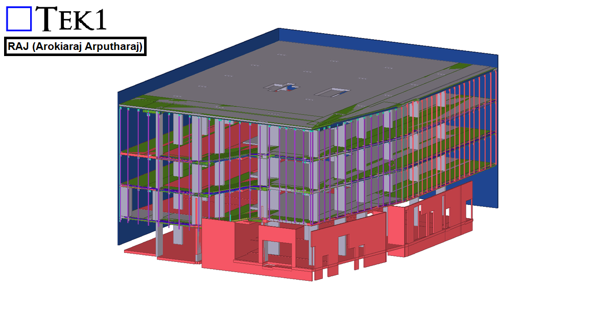
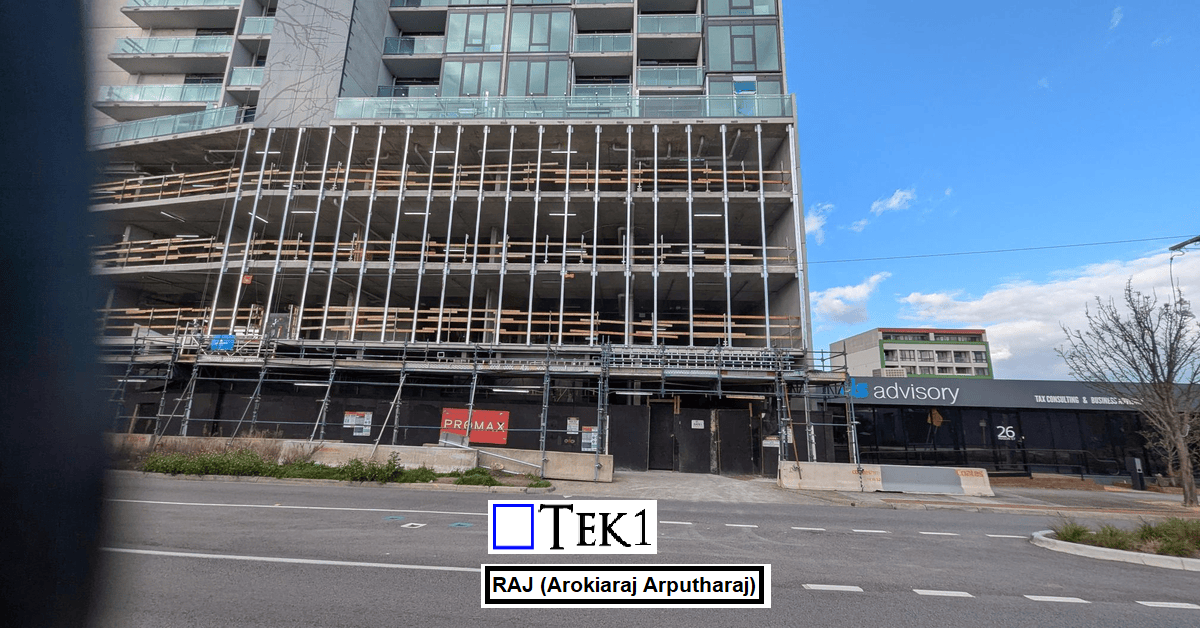
For the 27 Scott Street project, the client requested that the façade posts be installed with sufficient clearance so that the fixing anchors do not clash with the PT cable lines.
We carefully followed the client’s requirements and coordinated the design to ensure that the anchors clear the PT cable lines. The steel was successfully erected without any issues.
We would like to thank the client for giving us the opportunity to be part of this project.