Tag: steel detailing

  • Avoiding Errors In Updating Modified Drawings

    Avoiding Errors In Updating Modified Drawings

    When the model is amended after issuing the first set of drawings, the affected assembly drawings will appear as “Parts Modified” after numbering is completed. While updating such drawings, certain considerations are important to ensure effective and quick detailing.

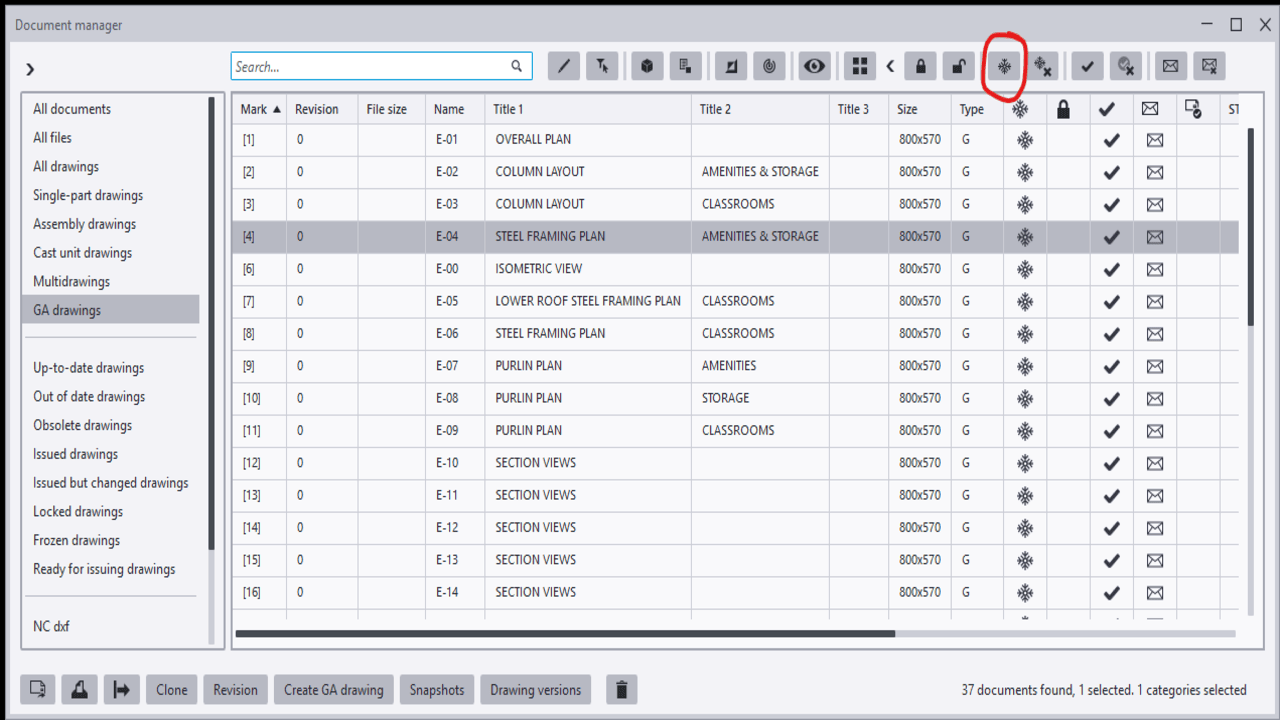
    1. Freeze Option

    When Freeze is OFF, Tekla automatically updates dimensions according to the movement of parts. While this may seem convenient, the decision to turn Freeze ON or OFF depends on the nature of the amendment.

    • If no new members are added to the assembly and only existing parts are moved, it is recommended to keep Freeze OFF, as Tekla will correctly update the dimensions.
    • If new parts are added to the assembly and Freeze is turned OFF, Tekla will automatically generate additional dimensions for the new members and may also alter existing dimensions. This can result in extra work to restore the original dimensioning arrangement.

    Guideline:

    • When no new parts are added, turn Freeze OFF.
    • When new parts are added, turn Freeze ON.
    2. Snapshot Option

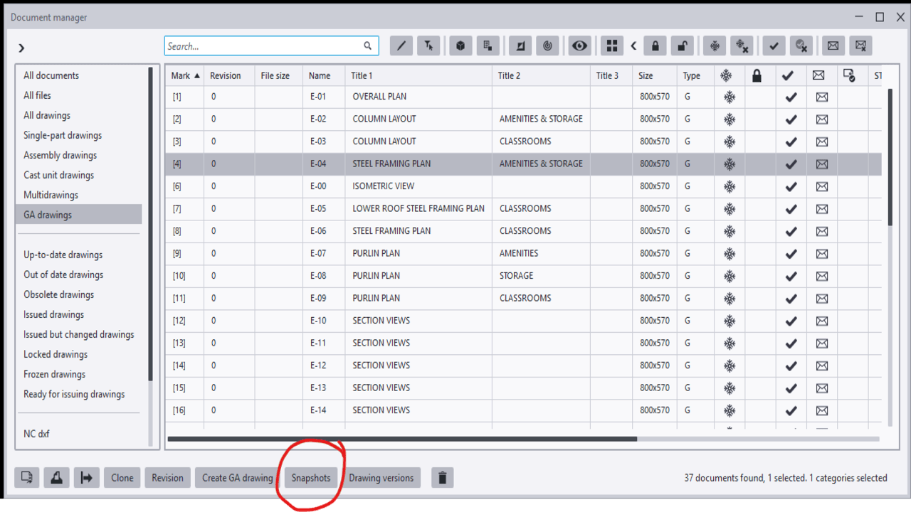
    Among the drawings marked as “Parts Modified,” not all drawings necessarily contain actual changes. Some assembly drawings may appear as modified because they share common connection components with other assemblies that were amended.

    In such cases, the drawing may not have any visible changes and may only require an open-and-close action. However, there is a risk that certain dimensions may be automatically deleted or altered by Tekla during the update.

    To avoid missing dimensions or unintended changes, the Snapshot option is highly useful. It allows detailers to compare the drawing before and after the update. By reviewing the differences, any unnecessary or unintended modifications can be identified and corrected, thereby minimizing the risk of errors.
  • Difference Between TEKLA “Export IFC” and IFC4

    Difference Between TEKLA “Export IFC” and IFC4

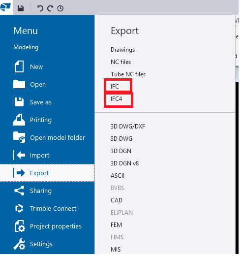
    When we export models from TEKLA Structures, we mainly see two options:

    • Export IFC (this mostly means IFC2x3 format)
    • IFC4 Export

    Both formats serve the same purpose—model interoperability—but they work differently, support different levels of data, and offer different quality of geometry.

    In this blog, we explore the key differences, benefits, and when to use each format.

    1. What is “Export IFC” (IFC2x3)?

    This is the old IFC format used by most companies for many years.

    Key points

    • Works in almost all BIM software
    • Shows Geometry is basic and sometimes rough
    • Limited property information
    • The File size is Bigger

    Best For

    ✔ General coordination
    ✔ Clients who request IFC2x3
    ✔ Old software compatibility

    2. What is “IFC4 Export”?

    This is the newer and more advanced format.

    Key Points

    • Geometry looks cleaner and smoother
    • Curved members (Hollow sections, pipes, elbows, etc.) look perfect
    • More detailed data (bolts, welds, assemblies)
    • Smaller file size in many cases
    • Better for new BIM tools

    Best For

    ✔ Modern BIM tools
    ✔ Better visual quality
    ✔ Detailed model sharing

    3. Quick Comparison

    FeatureIFC2x3 (Export IFC)IFC4
    GeometryBasic (Rough)Smooth & Accurate
    Curved ShapesApproximatePerfect & Precise
    File SizeLargerSmaller
    CompatibilityVery HighMedium
    Details LimitedMore Detailed
    convert IFC object to Steel MemberWork wellCan’t convert

    4. Which One Should You Use?

    • Use Export IFC (IFC2x3) if the client asks for it or if compatibility is important.
    • Use IFC4 if you want cleaner geometry and more detailed information.

    5. Final Summary

    • IFC2x3 (Export IFC) → Best for compatibility
    • IFC4 → Best for quality and smooth geometry

    If your client or BIM Execution Plan (BEP) does not specify the format, use IFC4 for best geometry

  • Hunter Street Ramps & Gates

    Hunter Street Ramps & Gates

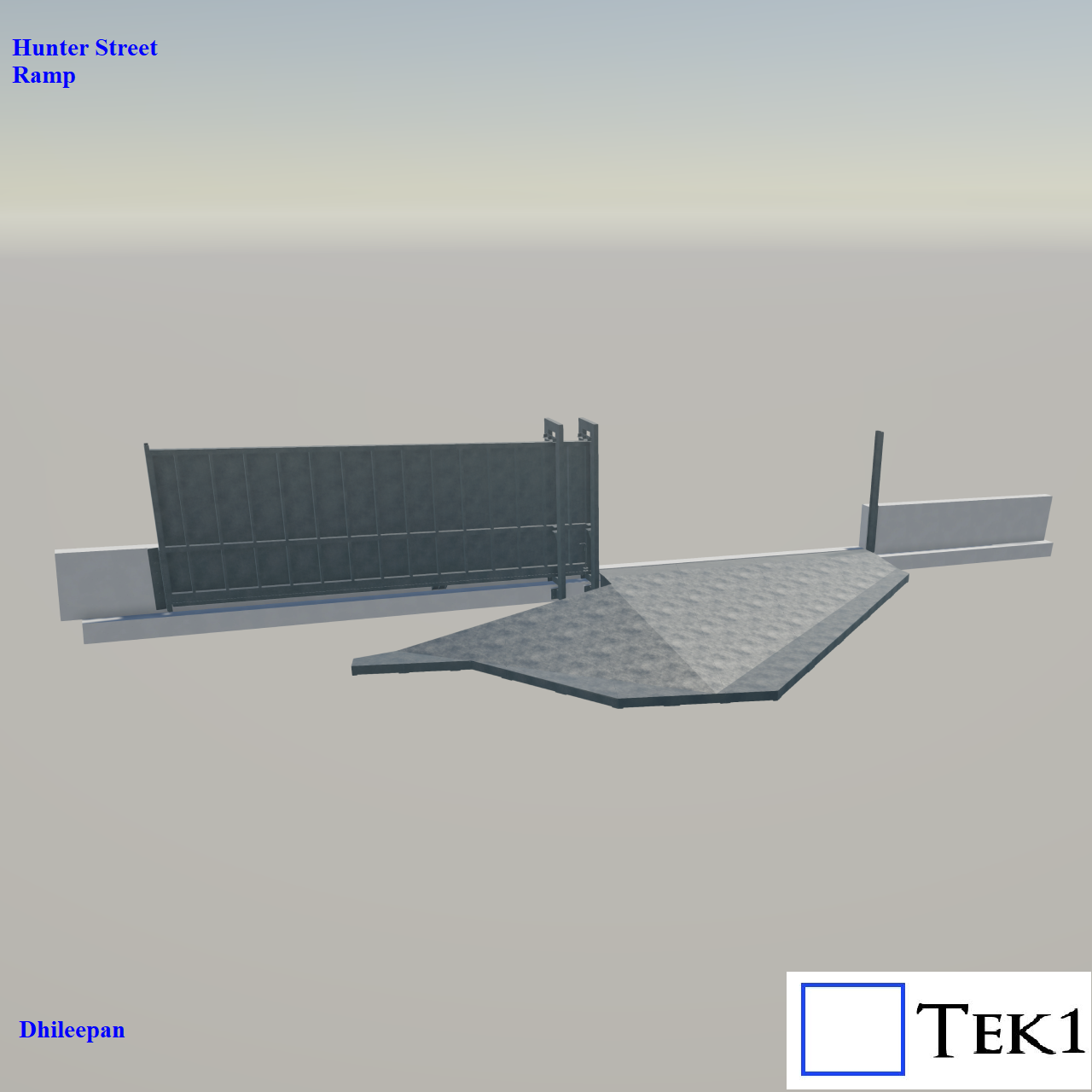
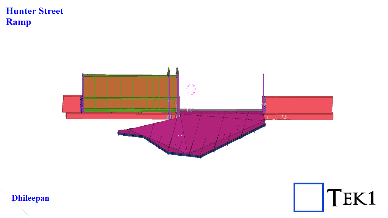
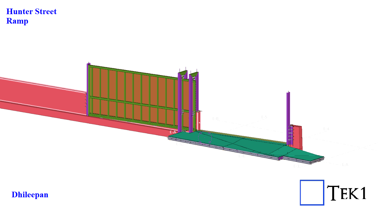
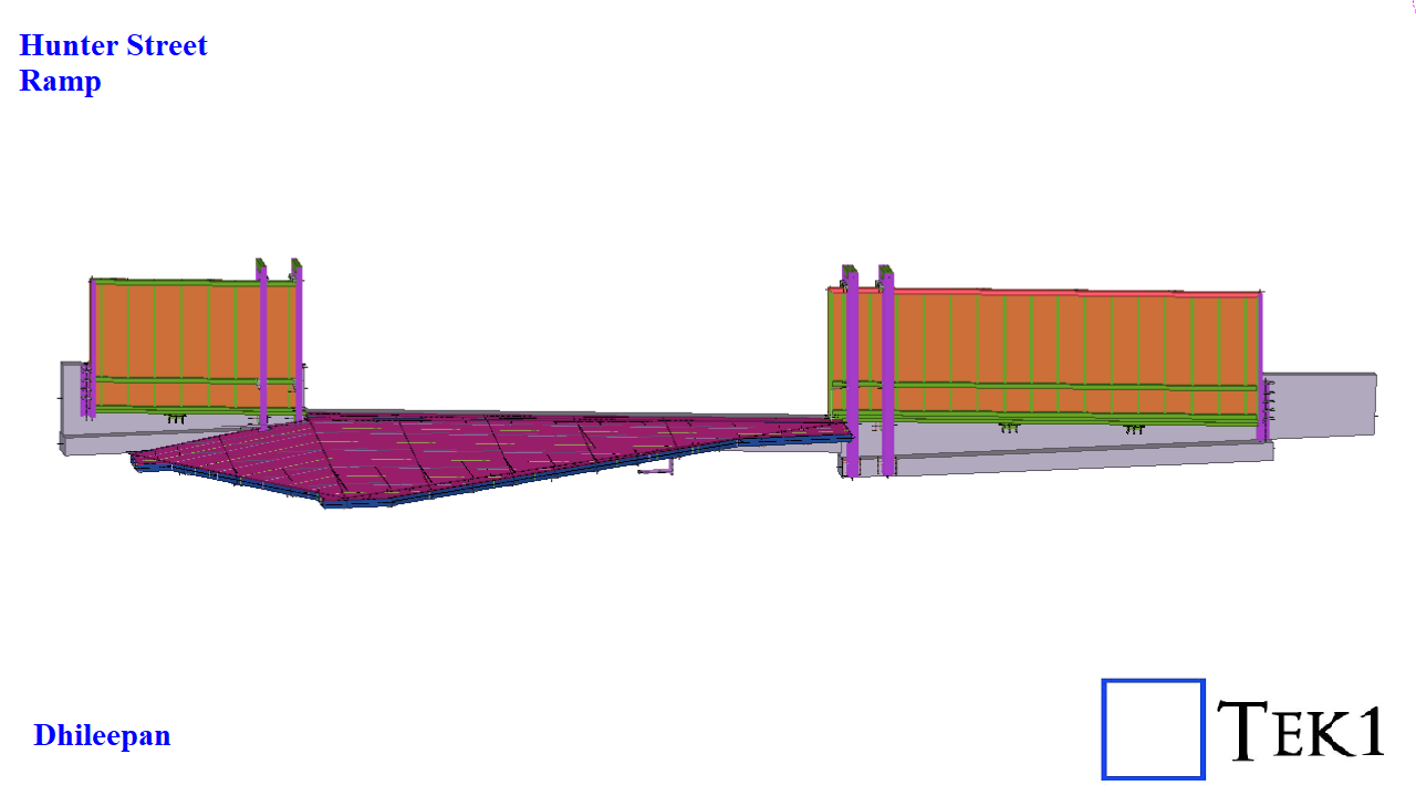
    The Hunter Street Project involves a total of three unique ramp and gate assemblies, each designed with a distinctive geometry and function.

    Unlike conventional ramps that slope in a single direction or follow a straight alignment, these ramps are far from ordinary. Each one features multiple slopes and apex lines, requiring precise modeling and coordination to achieve seamless transitions and accurate fitment on site.

    The associated gate systems include both single-leaf and double-leaf sliding gates, each integrated carefully with the ramp slopes to ensure smooth operation and proper clearances.

    Structurally, each ramp is composed of a series of 4 to 8 frames.
    Every frame includes:

    • A chequer plate deck at the top for slip resistance and durability.
    • A base plate at the bottom for connection and stability.
    • Waffle-type stiffeners sandwiched between, providing rigidity while minimizing weight.

    This setup requires engineering precision and modeling expertise. Tek1 had to provide inputs and suggestions to design the slopes in a way that ensures smooth operation of the sliding gates without imbalance.

  • TEK1’s Steel Detailing for Sydney Metro – Resolving Design Challenges – 5

    TEK1’s Steel Detailing for Sydney Metro – Resolving Design Challenges – 5

    We hope you found our previous blogs on the Sydney Metro project insightful. If you missed them, check them out.

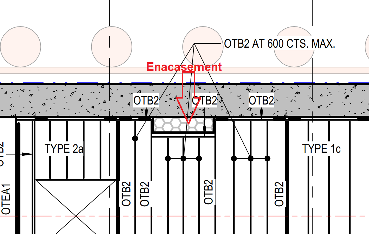
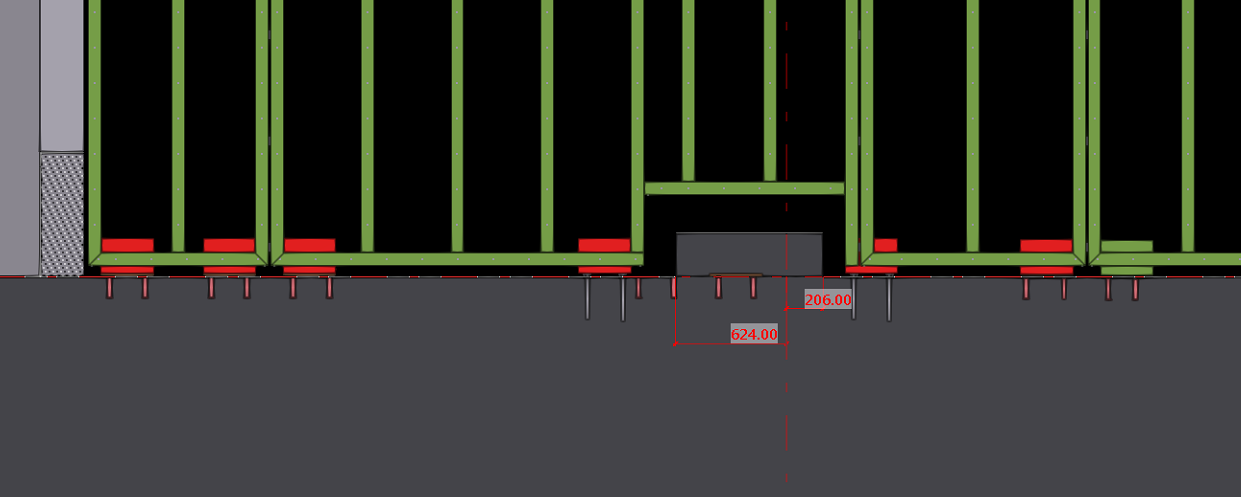
    In this blog, I’d like to share an important lesson about concrete encasement for conduits that every steel detailer should keep in mind.Normally, conduit encasement falls under electrical scope, so detailers don’t focus much on it. However, the encasement’s location and size can directly affect the steel layout — as we discovered in one of our projects.

    We detailed the steel as per design drawings, but on-site, the encasement dimensions varied. Some conduits were larger, others smaller, which caused clashes between the steel and the encasement, and in some areas, created unwanted gaps. This required on-site modifications to our steel.

    When detailing steel near conduit encasements, always verify the actual encasement size and location before releasing fabrication drawings. Small checks early in the process can prevent major issues and rework on-site.

  • TEK1’s Steel Detailing for Sydney Metro – Resolving Design Challenges – 4

    TEK1’s Steel Detailing for Sydney Metro – Resolving Design Challenges – 4

    We hope you found our previous blogs on the Sydney Metro project insightful. If you missed them, check them out.

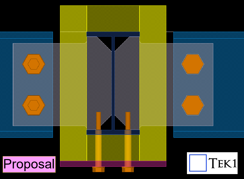
    In this blog, I’d like to share another connection detail we proposed to the structural engineer on the Sydney Metro project

    Since this is a metro project, fireproofing sheets are required on steel members as per the structural engineer’s specifications. However, the original connection details provided by the engineer were not feasible interms of installation of fireproofing sheets — they would make installing the fireproofing sheets difficult and time-consuming.

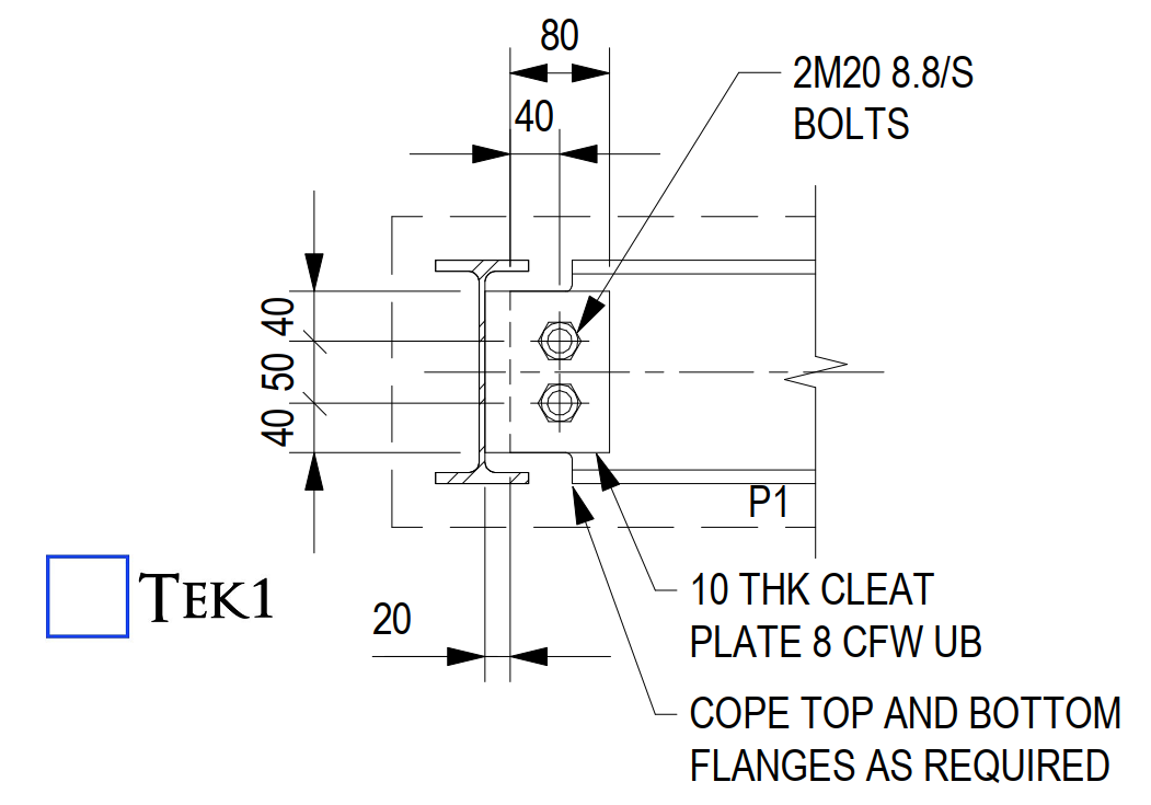
    Please see the connection details below. These are the standard connection details typically used for the steel members.

    However, applying these as-is may create difficulties during the installation of the fireproofing sheets.

    We identified this issue early in the detailing stage and proposed alternate connection details that would allow easier installation of the fireproofing sheets without compromising the structural requirement.

    The engineer reviewed our proposal, suggested a few adjustments like thickness changes, and then approved our updated connection details.

    Catching these issues early during detailing avoids major headaches later for installers and saves valuable time on-site

    Stay with TEK1 for more updates on this sydney metro project

  • How TEK1 Solved the Complicated Star Node Puzzle in Great EMU in the Sky

    How TEK1 Solved the Complicated Star Node Puzzle in Great EMU in the Sky

    At TEK1, we believe great detailing is more than just precision—it’s about understanding real-world challenges and turning complexity into clarity.

    The Challenge

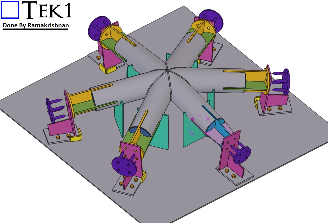
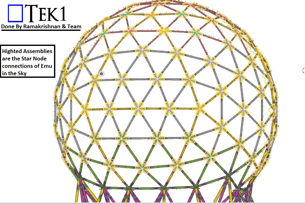
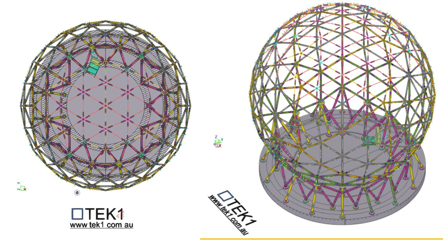
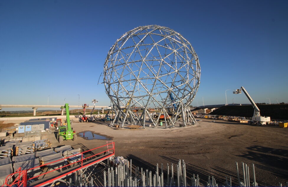
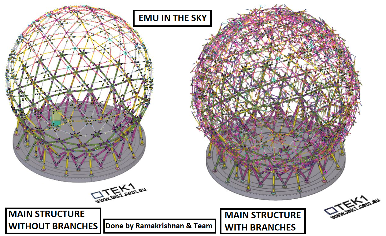
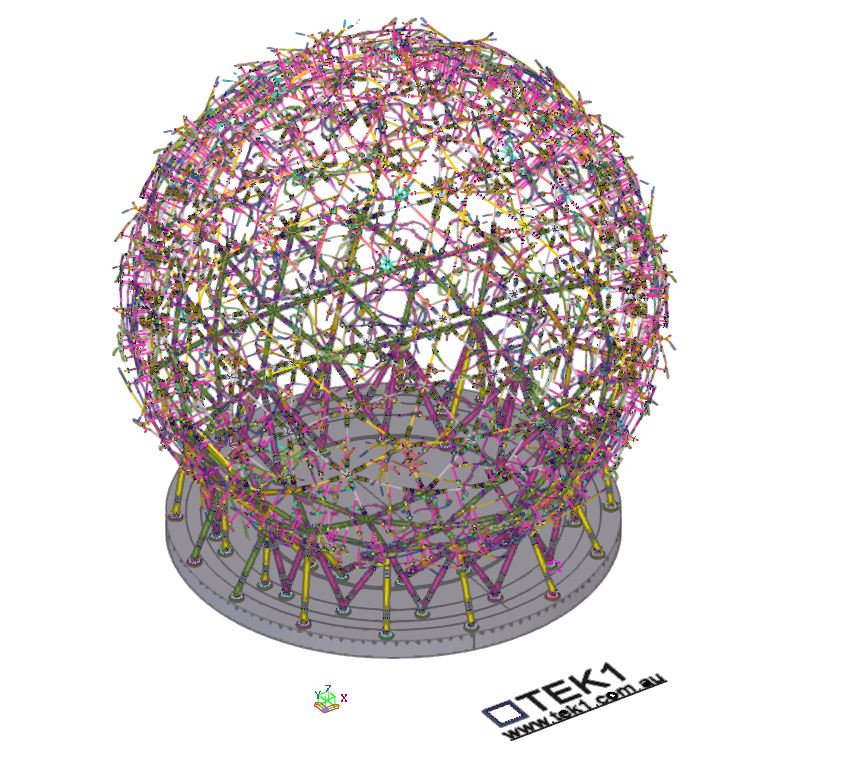
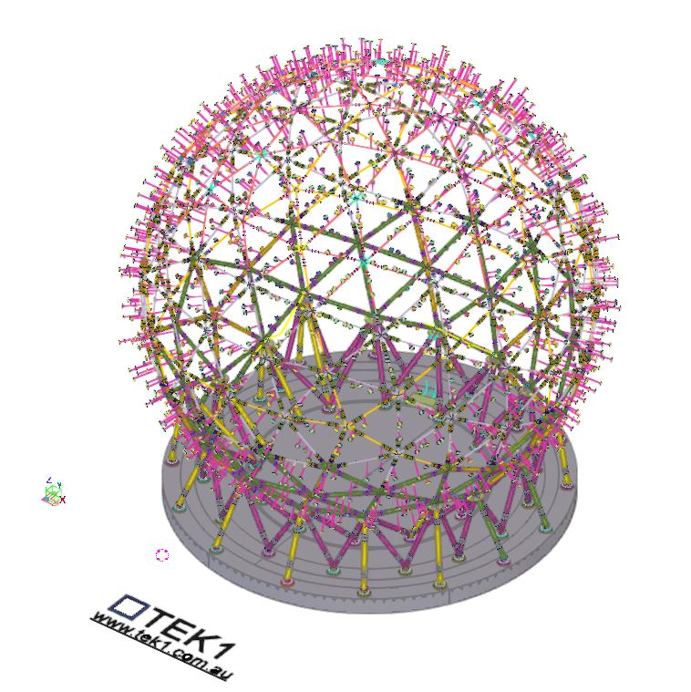
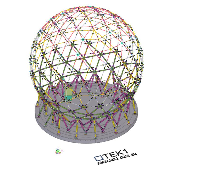
    The Great EMU in the Sky project presented one of the most unique and technically demanding structures we’ve ever worked on—a 30-metre-wide globe made up of 128 intricate “star nodes” connecting the bracing members.

    These nodes weren’t ordinary joints. Each featured 5 or 6 connection points and came in three different CHS sizes, with every arm set at unique, non-repeating angles.

    For the fabrication team, this posed a significant challenge:

    • 128 Complex Star Nodes, each with custom angles
    • Inconsistent geometries
    • Time-consuming and difficult to fabricate accurately

    Even with precise 3D modelling, the practicality of fabrication was proving to be a serious bottleneck. Something had to change.

    The Turning Point

    That’s when TEK1 took the initiative.

    Rather than simply delivering a model and walking away, we engaged directly with the fabricator to understand the issue from their perspective. We realized that even the most accurate detailing wasn’t enough—what the team needed was smarter, fabrication-friendly solutions.

    The Solution

    Our detailing team re-engineered how the star nodes were documented, presented, and ultimately fabricated. Key solutions included:

    • Custom fabrication jig design: We developed a dedicated jig that allowed star nodes to be fabricated with greater ease and precision, regardless of the angle configuration.
    • Standardized node sub-groups: We grouped similar nodes together to reduce variation and streamline production.
    • Detailed templates: For common angle types, we provided accurate templates to guide fabrication.
    • Visual fabrication aids: Clear drawings showing exact cuts, welds, and orientations for every node.

    The Result

    • Faster fabrication times
    • 🎯 Improved accuracy and alignment
    • 🔁 Reduced rework and error rates
    • 🤝 Stronger collaboration between design and workshop teams

    Most importantly, the fabricators were able to work with confidence, knowing each node would come together exactly as intended.

    Taking Detailing to the Next Level

    This project reinforced one of TEK1’s core values: true excellence in detailing comes not just from precision—but from empathy. When we truly understand the needs of the people building the structure, we unlock practical, buildable solutions.

    The Great EMU in the Sky is more than a globe—it’s a powerful example of what happens when detailers and fabricators work together as one team.

    📢 Call to Action:

    🚀 Have a complex structure or fabrication challenge? Partner with TEK1—where technical expertise meets buildability.

  • TEK1 Brings the ‘Great Emu in the Sky’ Sculpture to Life for Sydney’s M12 Motorway

    TEK1 Brings the ‘Great Emu in the Sky’ Sculpture to Life for Sydney’s M12 Motorway

    TEK1 is proud to be part of an iconic project—the ‘Great Emu in the Sky’ sculpture, a monumental 30-meter-high emu nest that will stand as a cultural landmark along Sydney’s M12 Motorway.

    A Symbol of Dharug Heritage

    The peanic structure celebrates the Dharug Community’s sacred creation story of the Great Emu constellation.

    A Landmark Visible from Land & Sky

    Positioned for maximum visibility, the sculpture will be seen by:

    • Road users
    • Pedestrians
    • Sydney Metro passengers
    • Even planes approaching and departing Sydney Airport

    Blending Art, Culture & Engineering

    The steel artwork will take on different forms depending on the time of day and viewing angles:We look forward to seeing this one-of-a-kind sculpture take its place in Sydney’s landscape, honoring history while welcoming the future.

    • By day, it will resemble an emu nest, crafted from signature steel “sticks” that reflect the natural landscape and traditional materials of the Dharug people.
    • By night, it will illuminate and reveal two emu forms, visible only from certain perspectives—mirroring the Great Emu constellation as it shifts throughout the six Aboriginal seasons.

    TEK1’s Role in Detailing the Sculpture

    A lot of technical challenges were navigated to ensure that this complex structure, could be fabricated and erected, cheaply and efficient. We will document this on our blog if you’re interested.

    Please refer to the below video which represents the various stages of on-going erection

  • SYDNEY METRO CITY & SOUTHWEST TUNNELGRC PANELS & ITS BRACKET

    SYDNEY METRO CITY & SOUTHWEST TUNNELGRC PANELS & ITS BRACKET

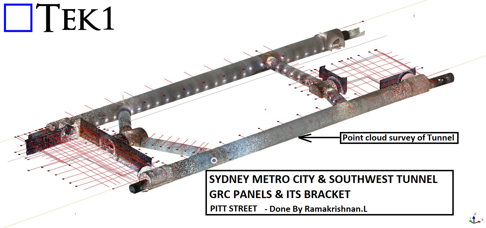
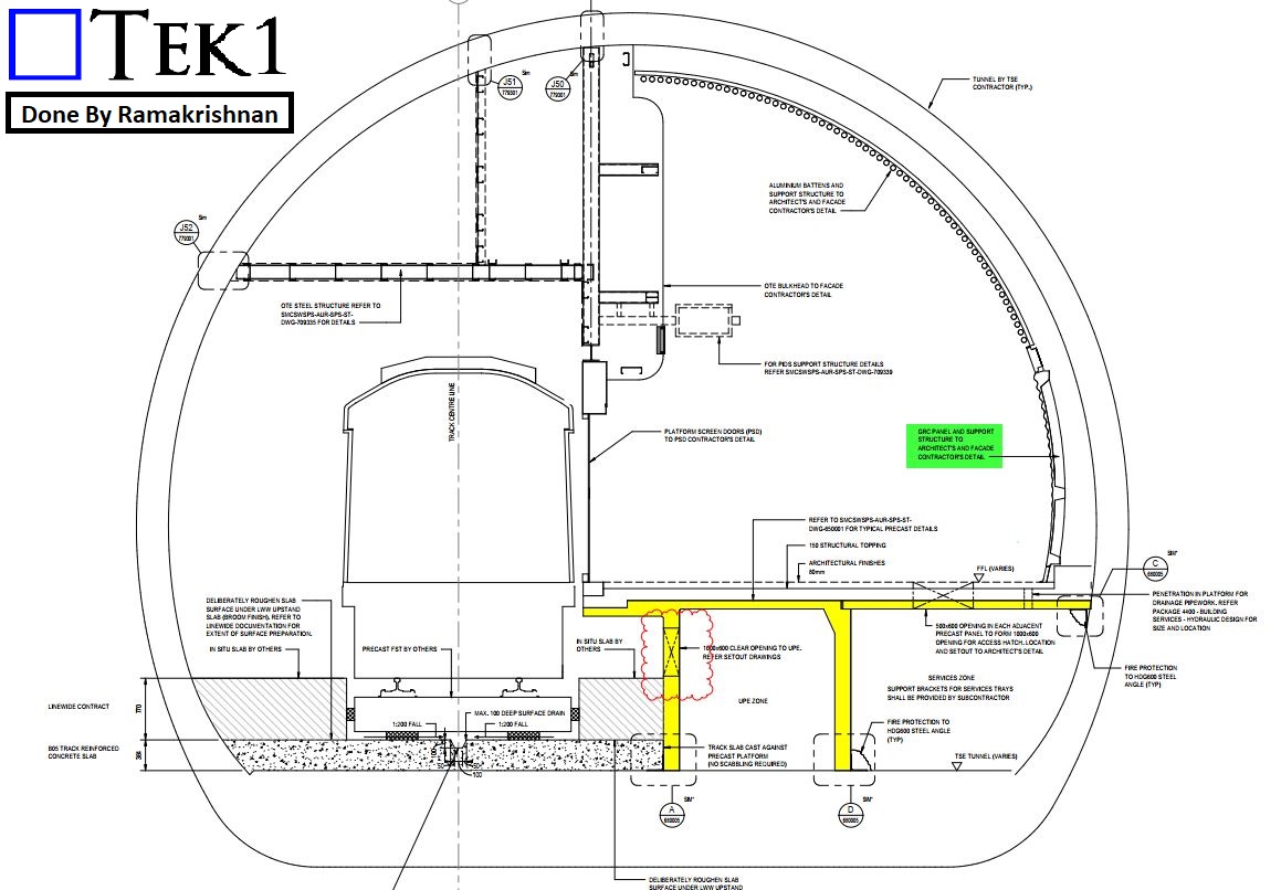
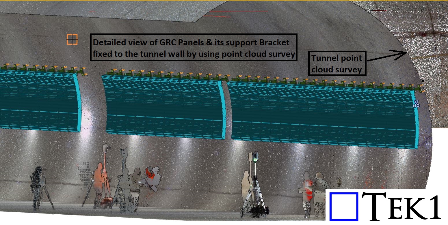
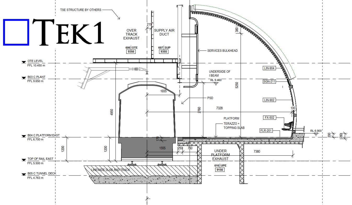
    TEK1, we recently had the opportunity to detail GRC panel brackets for a section of the Sydney Metro Tunnel, utilizing a point cloud survey to ensure precise alignment and installation.

    Project Overview

    The client provided a point cloud survey of the tunnel, allowing us to accurately determine the placement of GRC panels and their supporting brackets. Since tunnel walls are rarely perfectly straight—often featuring irregularities, ups, and downs—extra attention was required to ensure each bracket was positioned correctly for a seamless fit.

    Challenges & Solutions

    Efficient Coordination – By leveraging point cloud technology, we minimized potential site adjustments, streamlining the installation process for our client.

    As-Built Adjustments – The natural deviations in the tunnel wall’s shape meant that standard placements wouldn’t work. The point cloud data helped us fine-tune the bracket positions to match real-world conditions.

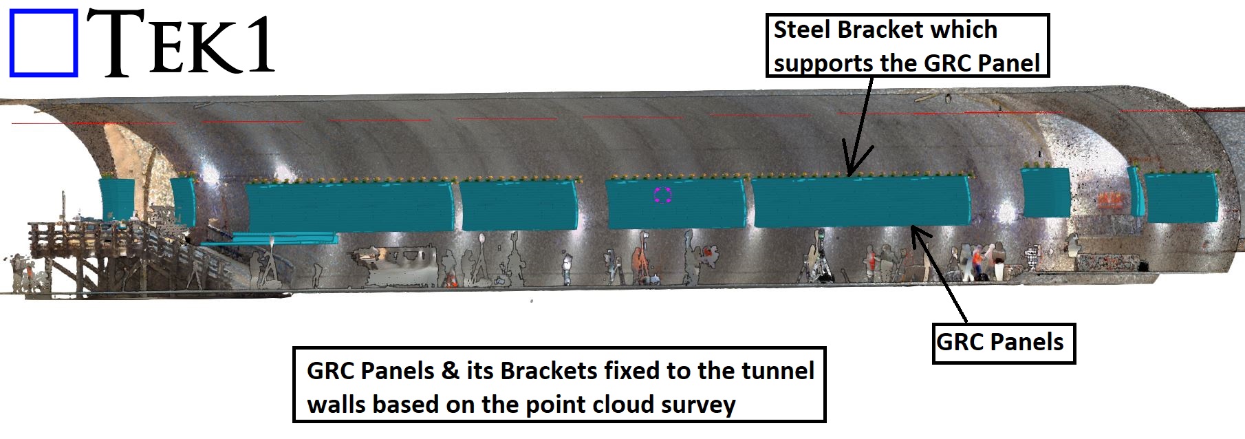
    Precision Detailing – Each steel bracket was meticulously detailed to accommodate the GRC panels, ensuring a secure and uniform installation.

    Conclusion

    Working with as-built tunnel walls requires high accuracy and adaptability, and this project was a great example of how TEK1 effectively integrates advanced technologies like point cloud surveys into our detailing process.

    Check out the snapshots below to see how the GRC panels are securely fixed to the tunnel wall using custom steel brackets.

  • Understanding PFC Shear Connection: A Practical Discussion

    Understanding PFC Shear Connection: A Practical Discussion


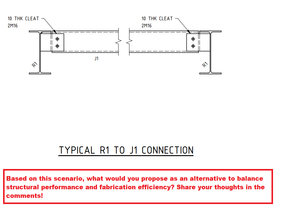
    Based on this scenario, what would you propose as an alternative to balance structural performance and fabrication efficiency? Share your thoughts in the comments!

    Introduction

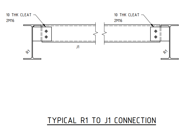
    Shear connections play a crucial role in structural steelwork, ensuring the stability and strength of a framework. One common method is the extended shear plate connection, as seen in the R1 to J1 connection detail. However, this method introduces bolt eccentricity, which could impact the overall efficiency of the joint.

    The Challenge

    In the given design, the PFC (Parallel Flange Channel) shear connection is detailed using an extended shear plate. While this is a standard approach, it inherently results in increased eccentricity due to the offset load transfer through the bolts. This can lead to additional bending moments in the connection, requiring careful consideration in the design phase.

    Possible Solution

    A potential improvement is to introduce a cope in the PFC section and utilize a simple shear connection instead. This modification would:

    • Reduce bolt eccentricity
    • Simplify force transfer
    • Enhance structural performance

    However, this approach was not accepted by the client due to fabrication ease considerations.

    Key Learning for Junior Engineers

    This case highlights a key engineering principle: design optimization vs. fabrication practicality. While structural efficiency is paramount, practical considerations such as ease of fabrication, cost, and site constraints often dictate final design choices.