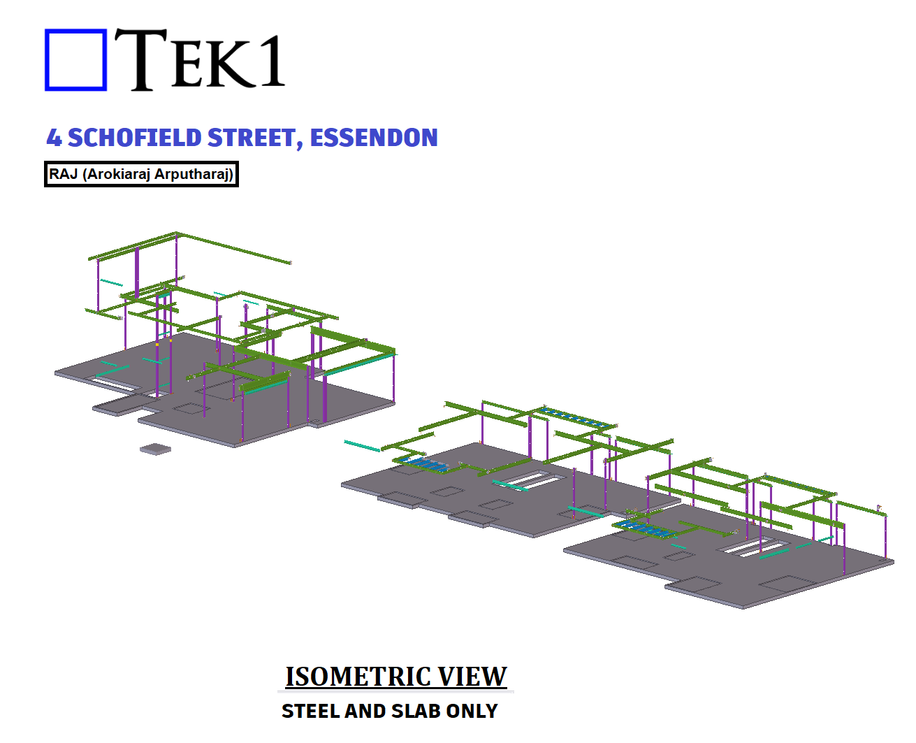

This article provides an overview of the important Australian Standards for steel detailing and serves as a practical guide for steel detailing projects in Australia.
Australian steel detailing requires more than accurately modelling beams, columns, plates and connections.
In addition, a professional steel detailer needs to understand the project documentation and the applicable Australian Standards.These standards provide an important technical framework for structural steelwork, fabrication, erection and access systems.
However, standards should always be considered together with the project’s structural drawings, specifications, contract documents and other requirements.
Therefore, understanding the applicable standards is an important part of producing accurate, coordinated and practical steel detailing documentation.
In particular, For steel detailing projects, several standards are particularly important, including AS 4100, AS/NZS 3678, AS/NZS 3679.1, AS/NZS 1163, AS/NZS 5131, AS 1657 and AS 1428.1:2021.
1. AS 4100 – Steel Structures
AS 4100 – Steel Structures is one of the primary standards used for structural steelwork in Australia. The current edition is AS 4100:2020.
Furthermore, standards Australia describes AS 4100:2020 as an important standard for the Australian steel sector and identifies it alongside AS/NZS 5131 as key guidance for structural steelwork.
In particular, AS 4100 is particularly important when interpreting structural design information.
Therefore, a detailer does not normally perform the structural engineer’s design, but needs to understand the design requirements sufficiently to produce accurate fabrication and erection documentation.
Typical detailing considerations include:
- Steel member sizes and grades
- Beam and column connections
- Base plates and holding-down bolts
- Bolted connections
- Welded connections
- Bracing arrangements
- Member orientation
- Connection clearances
- Structural tolerances
- Stiffeners and connection plates
- Shop and site weld requirements
In addition, the structural engineer’s drawings and specifications remain the primary design inputs.
Finally, the detailer’s responsibility is to accurately translate those requirements into constructible steelwork.
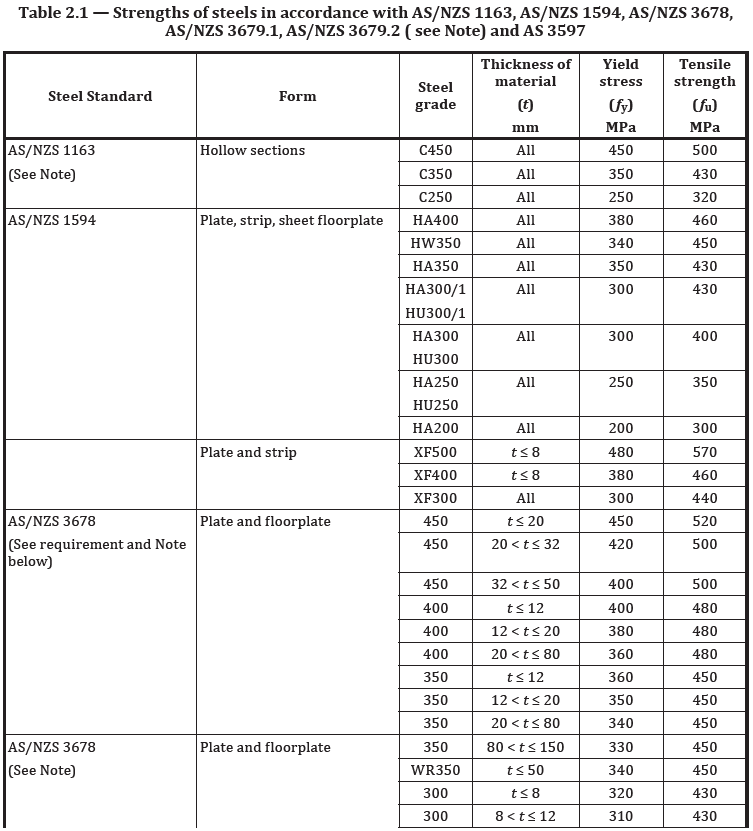
2. AS/NZS 3678 – Structural Steel: Hot-Rolled Plates
AS/NZS 3678 covers structural steel, including hot-rolled plates, floorplates and slabs.
Furthermore, standards Australia identifies it as one of the key structural steel standards published as part of its steel-sector standards work program.
In particular, This standard is important when specifying and detailing fabricated steel components such as:
- Base plates
- End plates
- Gusset plates
- Connection plates
- Stiffener plates
- Brackets
- Cleats
- Column cap plates
- Floor Plate
- Custom-fabricated steel components
When preparing shop drawings, the steel grade specified by the engineer should be clearly identified.
In addition, the detailer should also ensure that the material description used in the drawings and MTO corresponds with the project requirements.
For example, a plate shown as a particular grade on the structural drawings should not be changed to another grade simply because the alternative material is readily available.
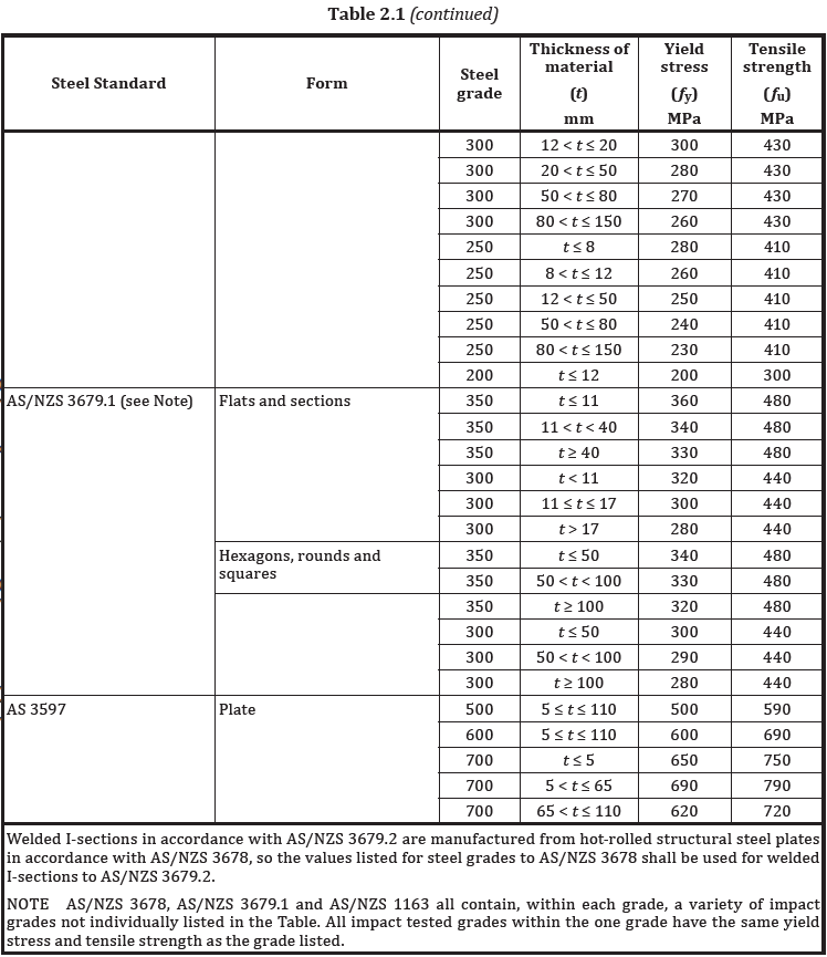
3. AS/NZS 3679.1 – Hot-Rolled Bars and Sections
Australian steel projects commonly use hot-rolled sections such as universal beams, universal columns and angles.
AS/NZS 3679.1 – Structural steel, Part 1: Hot-rolled bars and sections is therefore highly relevant to steel detailing.
During modelling and detailing, the detailer should verify:
- Correct member designation
- Section size
- Steel grade
- Member orientation
- Length
- End cuts
- Coping
- Notches
- Connection requirements
- Splices
- Stiffeners
- Fabrication requirements
Furthermore, accurate member identification is especially important in Tekla Structures because incorrect profiles or grades can flow through to fabrication drawings, NC files, MTO reports and material schedules.
4. AS/NZS 1163 – Cold-Formed Structural Steel Hollow Sections
Hollow sections are widely used in Australian construction for columns, beams, frames, handrails, balustrades and miscellaneous steelwork.
In particular, AS/NZS 1163 covers cold-formed structural steel hollow sections.
Common hollow-section profiles include:
- SHS – Square Hollow Sections
- RHS – Rectangular Hollow Sections
- CHS – Circular Hollow Sections
During the detailing process, it is important to correctly represent the section size and wall thickness specified by the engineer.
For example, an SHS column specified as SHS150 × 6 should not be modelled as SHS150 × 9 unless the change has been formally approved.
Furthermore, this is particularly important when steel members are connected to windows, doors, precast elements, concrete walls or architectural features where dimensional clearances are critical.
5. AS/NZS 5131 – Fabrication and Erection of Structural Steelwork
One of the most important standards for the fabrication and erection stage is AS/NZS 5131 – Structural steelwork – Fabrication and erection.
Furthermore, standards Australia explains that AS/NZS 5131 covers areas including fabrication, bolting and welding, surface preparation, corrosion protection, painting, galvanizing, site erection and modification of steelwork.
In particular, this standard is particularly relevant to the information shown on shop drawings.
Therefore, A professional steel detailer should consider fabrication and erection requirements when producing drawings, including:
Fabrication
Firstly, Drawings should provide sufficient information for the fabricator to manufacture the component correctly.
This may include:
- Plate dimensions
- Section lengths
- Hole sizes
- Hole locations
- Weld information
- Bolt information
- Cutting details
- Coping and notching
- Assembly information
- Part marks
Erection
In addition, Steelwork must also be practical to assemble on site.
Detailers should consider:
- Site access
- Erection sequence
- Bolt access
- Connection clearances
- Temporary erection requirements where specified
- Member identification
- Field welds
- Site connections
- Installation tolerances
However, a connection that looks acceptable on a computer model may still be difficult or impossible to install on site.
Therefore, Good detailing requires an understanding of both fabrication and erection.
6. AS 1657 – Fixed Platforms, Walkways, Stairways and Ladders
AS 1657 is particularly important for industrial steelwork, access platforms, stairs, ladders, walkways and handrails.
The standard addresses fixed means of access and safe working areas, including platforms, walkways, stairways and fixed ladders.
For steel detailers, this can affect many components, including:
- Stair stringers
- Stair treads
- Landings
- Handrails
- Guardrails
- Balustrades
- Toe plates
- Access platforms
- Walkways
- Fixed ladders
When detailing stairs and handrails, the detailer must carefully check the project requirements and applicable standard requirements rather than relying on assumptions from previous projects.
Important items to verify include:
- Stair geometry
- Handrail height
- Guardrail arrangement
- Openings
- Toe plate requirements
- Intermediate rail arrangement
- Clearances
- Landing dimensions
- Ladder configuration
- Connection details
The architectural drawings, structural drawings, specifications and project requirements should all be coordinated before finalising the detailing.
7. AS 1428.1:2021 – Design for Access and Mobility
AS 1428.1:2021 provides design requirements for access and mobility in new building work. In particular, it covers requirements that can affect accessible paths, ramps, stairs, landings, handrails, circulation spaces and other accessibility-related elements.
For steel detailers, this standard can be relevant when detailing commercial building stairs, ramps, handrails, balustrades, platforms and other steelwork that forms part of an accessible path of travel.
During the detailing process, the architectural and engineering drawings should be checked carefully for accessibility requirements. For example, dimensions, clearances, handrail arrangements, ramp and landing requirements may need to be coordinated with the structural steelwork.
In addition, the detailer should coordinate the steelwork with architectural layouts and project specifications to avoid conflicts with doors, walls, finishes and other building elements.
However, the steel detailer should not independently determine accessibility compliance. Instead, the applicable project requirements, architectural documentation, NCC requirements and relevant engineering information should be followed.
Therefore, where AS 1428.1:2021 applies to the project, its requirements should be considered during the steel detailing and coordination process.
8. AS/NZS 5131 and the Importance of Steel Detailing
Australian steel detailing is closely connected to fabrication and erection.
Before finalising the steelwork, several practical questions should be considered:
- Can this member actually be fabricated?
- Is the connection suitable for welding or bolting as detailed?
- Will the fabricator have sufficient access to complete the weld?
- Can the erector install the bolts safely and efficiently?
- Is there sufficient clearance around the connection?
- Have all site welds and site bolts been clearly identified?
These questions can prevent costly fabrication changes and site modifications.
AS/NZS 5131 provides a framework for fabrication and erection practices, making coordination between engineering, detailing, fabrication and erection particularly important.
9. Australian Standards and Tekla Structures
Modern steel detailing is often completed using 3D modelling software such as Tekla Structures.
However, software does not automatically guarantee compliance with Australian Standards.
For this reason, The detailer still needs to interpret the project documentation and apply the correct requirements.
A typical workflow may include:
Structural Drawings → Architectural Drawings → Specifications → Engineering Information → 3D Model → GA Drawings → Shop Drawings → MTO/BOM → NC Files → Fabrication → Erection
At every stage, coordination is important.
For example, if the architectural drawing shows a window in the same location as a structural column, the conflict should be identified and raised as an RFI before fabrication.
Similarly, if a structural drawing requires a particular connection but the connection cannot be fabricated or erected as shown, the issue should be referred back to the engineer rather than resolved through an unauthorised design change.
10. Coordination Between Architectural and Structural Drawings
One of the most common challenges in Australian steel detailing is the difference between architectural and structural information.
Typical discrepancies include:
- Different dimensions
- Different floor levels
- Missing structural members
- Different opening sizes
- Different wall locations
- Architectural elements not shown on structural drawings
- Structural members conflicting with windows and doors
- Missing site survey information
Therefore, the steel detailer should identify these discrepancies during the checking stage.
An effective RFI should clearly state:
- What the drawings show
- What the conflict is
- Why it affects the steelwork
- What information is required
- The proposed solution, if appropriate
As a result, this approach reduces assumptions and helps maintain a clear record of design decisions.
11. MTO and Material Identification
Australian steel detailing is not complete when the 3D model is finished.
In addition, The model must also produce accurate fabrication information and material quantities.
The MTO/BOM should correctly identify:
- Member marks
- Part marks
- Section sizes
- Plate sizes
- Steel grades
- Quantities
- Lengths
- Weights
- Bolts
- Miscellaneous steel
- Coatings or finishes where required
However, incorrect modelling can result in incorrect MTO quantities and fabrication information.Therefore, model checking should be performed before issuing the final material report.
12. Common Steel Detailing Mistakes
Some common problems encountered in Australian steel detailing include:
Incorrect steel grade
Firstly, using the wrong material grade can create fabrication and compliance issues.
Incorrect member size
Similarly, a small difference in section size can affect connections, clearances and structural performance.
Missing connection information
In addition, Connections must be clearly detailed in accordance with the engineer’s requirements.
Poor bolt access
However, a connection may be geometrically possible but impossible to install because the erector cannot access the bolts.
Architectural conflicts
Furthermore, columns, beams and bracing may conflict with doors, windows, services or architectural finishes.
Missing site information
Without accurate site measurements or survey information, existing conditions can be difficult to verify. Therefore, accurate site information is important when finalizing the steelwork.
Unapproved design changes
Finally, a steel detailer should not make structural design changes without appropriate engineering approval.
13. The Role of a Professional Australian Steel Detailer
A professional steel detailer acts as an important link between engineering design and steel fabrication.
Therefore, the role involves much more than simply drawing steel members.
For this reason, A competent detailer should be able to:
- Read structural and architectural drawings
- Interpret engineering specifications
- Understand relevant Australian Standards
- Model steel accurately
- Prepare clear GA and shop drawings
- Identify design conflicts
- Raise RFIs
- Coordinate with engineers and architects
- Prepare accurate MTO/BOM reports
- Consider fabrication requirements
- Consider erection requirements
- Check connections and clearances
- Maintain revision control
- Deliver accurate fabrication information
Conclusion
Australian steel detailing requires a combination of technical knowledge, practical fabrication experience, attention to detail and understanding of Australian Standards.
In Particularly the Standards such as AS 4100, AS/NZS 3678, AS/NZS 3679.1, AS/NZS 1163, AS/NZS 5131, AS 1657 and AS 1428.1:2021 provide important references for different aspects of structural steelwork.
However, standards should not be viewed in isolation.
Therefore, The successful steel projects depend on coordination between the structural engineer, architect, steel detailer, fabricator and erector.
The goal of professional steel detailing is simple:
Create accurate, clear and buildable steelwork information that can be safely fabricated, delivered and erected on site.
Finally, for current editions and official information, always refer to the applicable project specifications and the official Standards Australia catalogue rather than relying on outdated or unofficial copies of standards.