Tag: #TEK1-RAMKRISH-PROJECTS
-
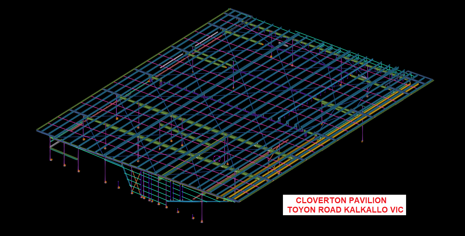
CLOVERTON SPORTS PAVILION. TOYON ROAD KALKALLO VIC.


CLOVERTON SPORTS PAVILION project successfully Done by TEK1 PTY LTD successfully completed this pavilion project with nil error. Wonderful Feedback received from our client.
-
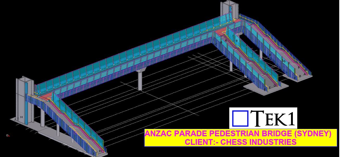
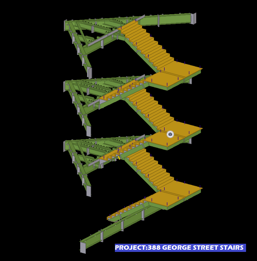
ANZAC PEDESTRAIN BRIDGE (SYDNEY). MOORE PARK, NSW.

This Anzac Pedestrain Bridge is succesfully detailed by TEK1 pty Ltd with out an error.
For FLY-OVER Video please refer attached link https://www.youtube.com/watch?v=O_Q-2eaINgU
-
Purlin Bundle Report.
What is Purlin bundle report & why its required?
A report which lists Bundles numbers and purlin numbers under it. When the purlins are delivered to site, they come in packs & located exactly in the areas as noted in the Marking plan.A set of purlins are grouped together as bundle & are delivered to site. While purlin erection, the erector refers only the Bundle mark in the marking plan & erects the corresponding bundle. Otherwise they have to segregate all the purlins & it would demand some extra efforts to erect.
If we provide this bundle report it would be easier for the erector to bundle the purlins & erect. Also it would give some additional value to our work.
For Report & Marking plan details. Please refer below snaps.
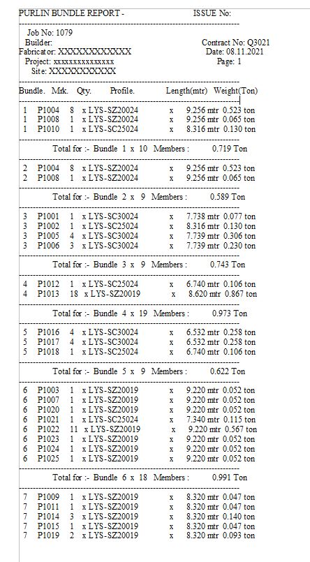
Please refer Below snap which shows the Purlin Bundle details in our Purlin Marking plan

-
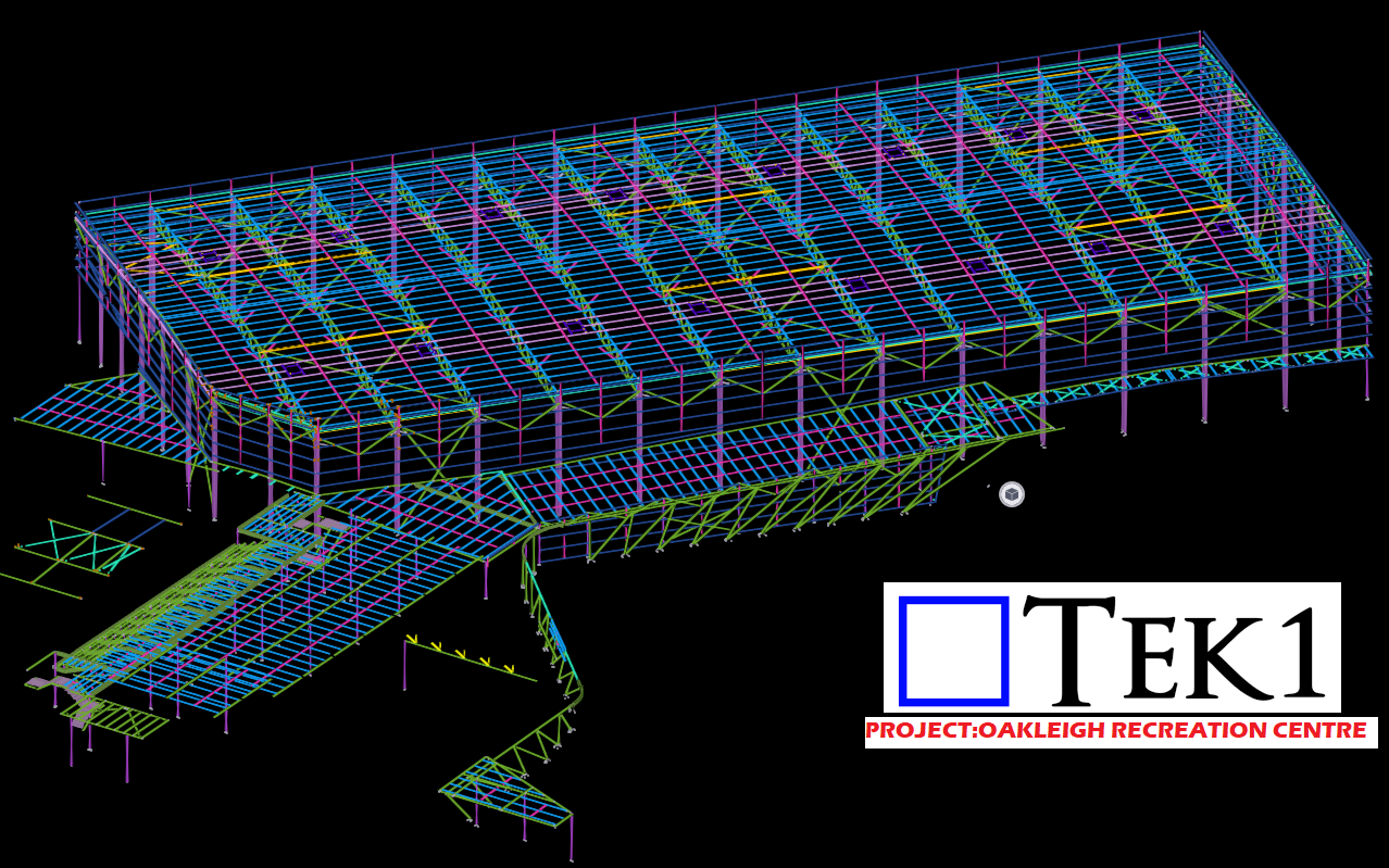
Project :OAKLEIGH RECREATION CENTRE – TEK1

TEK1 Steel Detailing Company Provides high-quality Miscellaneous Steel detailing Services internationally.
We have the best engineers and they all are professional and highly qualified in this field. they normally deal with columns of various shapes, sizes, , and miscellaneous steel parts.
We have successfully provided miscellaneous steel detailing services to all our esteemed clients by adhering to all the necessary codes and standards.
connect with us today regarding your queries related to miscellaneous steel shop drawings and we will get back to you with the answers shortly.Why Choose us:-
Quick approvals by clients.
Simple and Easy design modifications.
Easy and better client communications.
Team of more than 40+ engineers, designers, and drafters
Assurance of data security and confidentiality.
Completed more than 1000+ projects.
Accurate and result oriented delivery of the work.For More Details
Please Contact Us at :- koshy@tek1.com.au
Website:- https://www.tek1.com.au
-
Liverpool Catholic club
Liverpool Catholic Club is in Hoxton Park Road, Liverpool West NSW 2170
Author: Ramakrishnan L
Tek1 has completed this rather complicated project “Liverpool Catholic club”, for Gonzo Engineering, Simon Hatton as the Lead Estimator for Gonzo Engineering & the builder in this instance was Kane Constructions
The project was complex demanded a very high level of detailing Knowledge. We have put our best guys on this job. They have done wonderfully well in completing this project without a hitch.
If you want steel shop drawings for a project you are working on, please feel free to call Koshy on: (03) 9560 6397 / +61 3 9560 6397
For erection video please chk below
A post shared by Liverpool Catholic Club (@liverpoolcatholicclub)
Some of the erection pics & model snaps for this project is given below, Kindly have a look

LIVER POOL CATHOLIC CLUB SITE ERECTION PIC-01 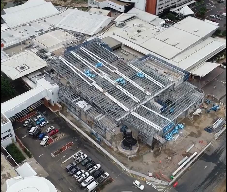
LIVERPOOL CATHOLIC CLUB SITE ERECTION PIC-02 
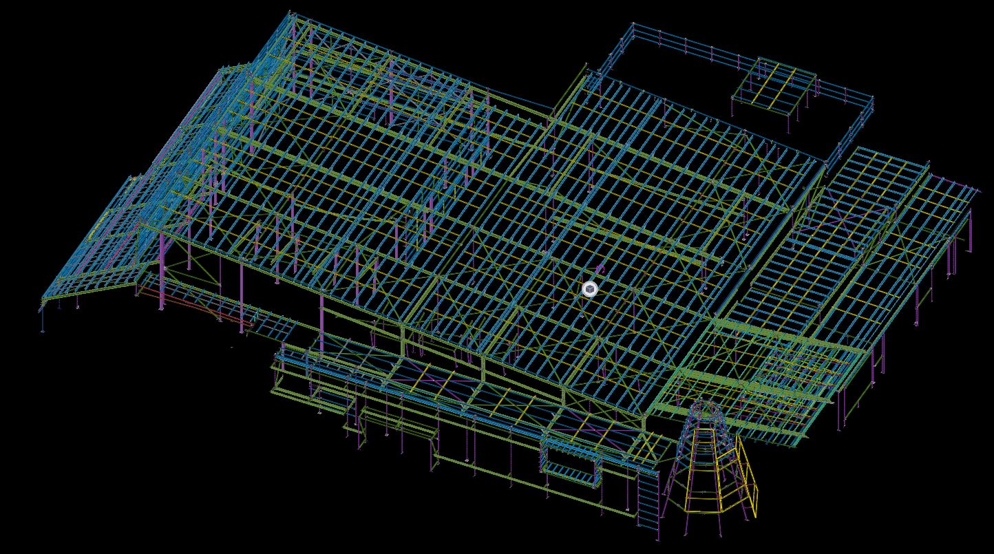
TEK1 MODEL SNAP 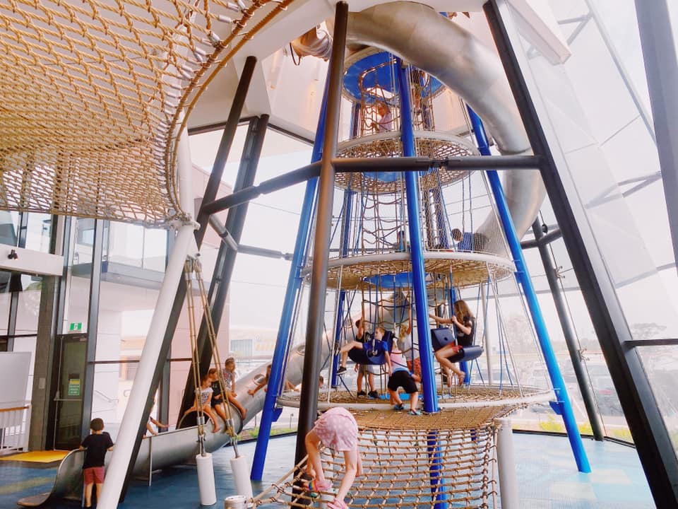
KIDS PLAYING CENTRE CONICAL SECTION 
-
STEEL MODELER ATTENTION – DEALING WITH CAMBER
TEK1 worked in a railway foot over bridge with 2 lifts, 2 ramps, 2 stairs connecting platform and overpass, a canopy and 7 platform stairs. The main challenge is the over pass. As per design, the steel truss after erection must be cambered to different millimeters at different intervals. There were two terms “Residual camber” and “Reference Profile” in the structural drawing. Many do not that what these mean. Any misunderstanding about these terms would result in redoing the entire overpass. But TEK1 had good understanding of these terms and avoided heavy rework.
This blog is to educate the modelers regarding residual camber and reference profile. Kindly refer the camber diagram below.

The residual camber at the south end is 67mm and reference profile at the same end is 62mm. Residual camber is the camber value which must be given in the steel assembly drawings which the steel detailer supply. Whereas reference profile is the camber value which the structure attains after applying all the dead loads. Here the dead loads are concrete load and self weight of the steel.Hope this helps you. Thanks for reading.
Ramakrishnan.L
TEK1. -
CHECK TRANSPORTATION FEASIBILITY WHILE WORKING IN AN EXISTING STRUCTURE
The conventional maximum transportation size for an assembly is 12m x 2.5m x 2.5m. This value is not applicable for all the conditions.
TEK1 executed an alteration work inside Canberra airport. Everything that enters an airport must go through the checking / screening area. As per design, the size of assemblies were more than 9m & we were not sure whether these assemblies could be transported into the Airport. So, TEK1 raised a query regarding this. The client agreed to reduce the size of transported assemblies.
Lesson: Whenever a work is carried out inside an existing building, consideration must be given for taking in the assemblies i.e. door/entrance size is mandatory. Since a completed airport terminal is a closed roof structure, cranes cannot be used for erection. Here the erection is done with the help of genie lifts. Weight carrying capacity of the erection machinery must also be taken into consideration.
See below design snap & TEK1 proposal markup for splice location.
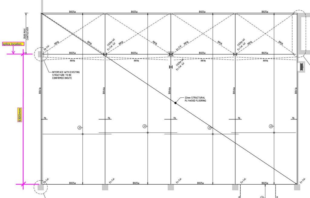
ABOVE SNAP TAKEN FROM STRUCT DESIGN. SHOWN ASSEMBLY SPLICE LOCATION AS 9300 mm.
PLEASE REFER BELOW SNAP WHICH SHOWS PROPOSAL MADE FROM TEK1 & THAT WAS APPROVED BY STRUCT ENGINEER.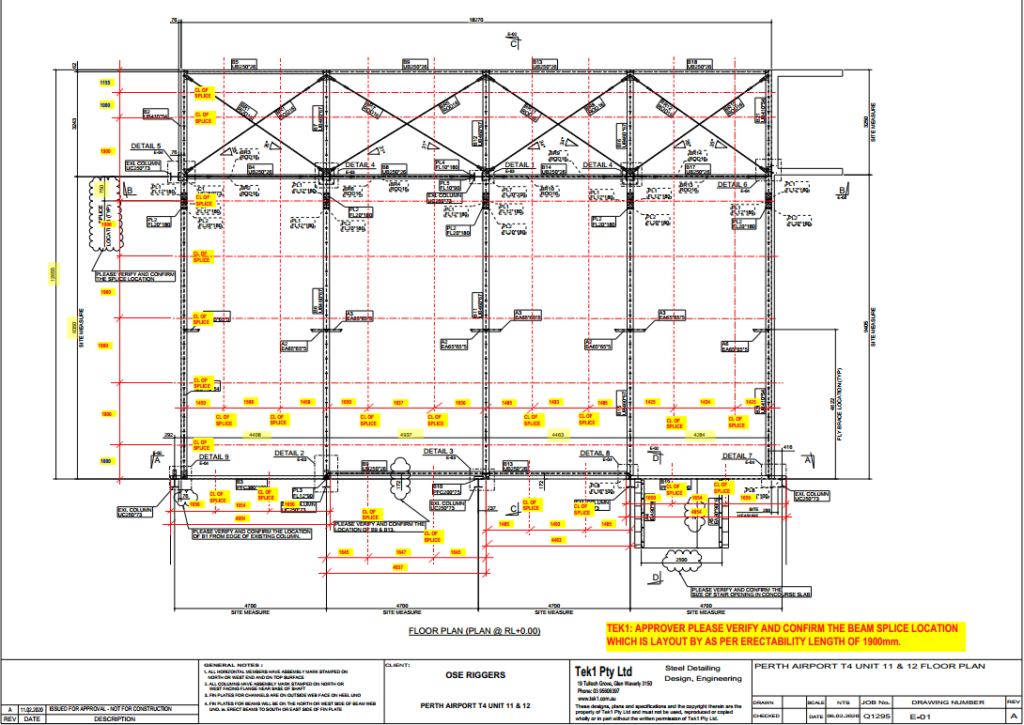
-
ISSUES OF EXPORTING DSTV TO DXF WITH CSK BOLTS IN TEKLA MODEL
Wherever Countersunk bolts are provided in a model, it is advised not to send NC DXF files to the client for the corresponding plate/shaft. This is because the hole dia in the generated NC & DXF file is not the actual bolt dia but it is the dia of the countersunk head. Therefore, the hole dia in the plate/shaft is much higher than the actual value. Hence, it is advised not to send NC DXF files for plates/shafts which has countersunk holes.
But, when the client demands for NC DXF files even for plate/shaft with CSK bolts, the generated NC DXF files must be manually edited such that the CSK hole dia in the NC DXF files is bolt dia + 2mm(Tolerance).
Also the tolerance for CSK bolts must be 2mm everywhere irrespective of the members the bolt is connecting i.e, whether it is steel to steel connection or steel to concrete connection the tolerance for CSK bolts must be 2mm.
By Ramakrishnan.L
TEK1