Sometimes we have a need to identify – and quickly – lines which are open and lines which are closed – especially prior to running any operations on those lines involving regions.
Here is a demo of a little plugin I wrote.
It goes through the modelspace and finds all the line segments which are connected to each other. It further goes on to query which line segments are closed and which are open.
Getting AutoCAD to do this quickly was quite a task. But am very pleased with the speed – only 1-2 seconds when you’re iterating through a few thousand lines. Not bad.
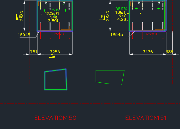
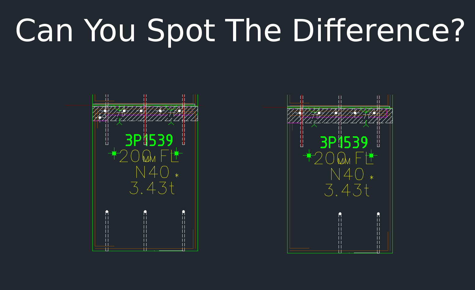
When drafting for precast panels, there is need to check differences with different versions of the shop drawing. Manual checking a bit difficult. Automation tools help
This tool compares panels and imports differences. Yet another reason why Tek1 is leading the world in precast panel drafting. Shop drawing / Layout panel discrepancies are a thing of the past.
Suppose someone makes a change in the layout but forgets to do so in the shop drawing (and vice versa). If you move a cast in plate, and if it’s actually produced and taken to site, then you have a big problem, and a big cost. How are you going to identify the differences which exist in the thousands of panels that you make? What if you had a tool which allowed you to easily identify differences between the two drawings?
This is what this Panel Comparison tool does. It gives you confidence that somebody hasn’t made a boo-boo. And moreover, if somebody has made one, then this tool identifies sloppy shop drawing practices.
Here is the demo. I hope you enjoy it!
Gif Demo with User Interface:
Now we have a user interface which allows us to click on items in a window and access them easily in AutoCAD. Written by Ben Koshy.
It can work for all clients with only very minor modifications. Very well abstracted out in the code.
It is super fast. Comparing the thousands of elements in each drawing takes a bit of computing power – but with smart algorithms, you can cut down the time.
It works for all sorts of edge cases – what if the panel was made up of arcs, polylines and straight lines – this plugin can handle all sorts of things. It can also handle voids in the panel?
What if an item is on the edge of a panel line – it can handle that was well.
Every single panel that we draw will go through the above practices. It should give you a lot of confidence that we’ll get the drawings right. Yet another tool in the Tek1 arsenal that allows this firm to lead the industry in Precast Panel drafting.
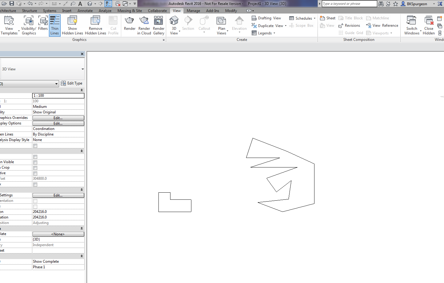
Demonstrates the ability to transform 2D AutoCAD files into a native Revit format.
This is a demo of my latest plug-in which demonstrates a proof of concept – i.e. a MVP (Minimum Viable Product). The programming was a little trickier than normal – because we are not using the .NET API, but the COM Interop API and the Revit API – something which I have not really explored prior to this post.
What does it do?
If you have drawn some panels in AutoCAD, this plugin allows you to quickly and accurately convert those panels into Native Revit walls. You can then give Architects and builders those Revit files – otherwise it will be very difficult for them to work with AutoCAD files.
This gives you a competitive advantage over your competition, because you can quickly and easily do it – and it makes the job of architects and builders easier – especially given the rapid push everyone’s making into BIM technologies.
(I’ve made the command so that it works even when you have AutoCAD open. This allows detailers to quickly switch to Revit and AutoCAD and to delete and restart if need be. Also requiring that AutoCAD be open ensure that detailers know exactly what file they are working with and what files they are converting. It eliminates a whole lot of errors.)
It’s not very often that I write something on the Autocad .net API, so here’s something which you, I suppose, will need one day:
If you want to compare two lines, with a tolerance, in a collection then you’d need a LineComparer. The MSDN guide says that one should inherit from EqualityComparer, so unquestioningly, I did their bidding. The results are as below.
Take careful note of the Hashcode. You want lines that are similar – and are within the tolerance to return the same hashcode. If they are outside the tolerance then the chances of two different lines returning the same hashcode is minimal.
Lines are equal if their start and ends points are equal (or vice versa). They are also more or less equal if they return the same hash code. In such cases, then the equals method is run.
understand the importance of putting holes in the beams in order to allow for the erection of stud walls.
What is a stud wall?
A stud wall is made up of:
A frame (in our situation this frame will be a steel frame) and
timber members which go in between the steel frame and
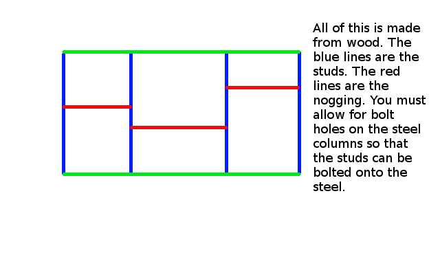
a covering of 13 mm plaster board to cover the frame. The plaster board covering is not shown in the diagram below.
In steel stud walls, light steel pressed members or standard steel studs (mostly standard steel studs) are used instead of timber.
Please view the diagram below.
Shows what stud and nogging members are.
What is nogging?
Do you see the horizontal 90 x 45 timber pieces – the short red horizontal timber members? These short timber members are called nogging.
The nogging members of a stud wall are usually smaller in size than the main vertical members.
Nogging members run horizontal and give some strength to the wall.
Inside of the wall is empty space. Insulation material can be put in there.
Cross pieces are called NOGGING.
The Key Point of this lesson:
It is important that you provide dia 14 holes on the steel beams and columns so that the timber pieces can be bolted to the steel pieces. Imagine you have some steel beams/columns and also some timber. How will the timber columns be attached to the steel columns so that the structure doesn’t move? Holes need to be drilled so that the timber pieces can be bolted to the steel beams. You need to provide holes in the steel so that the timber members can be bolted to the steel.
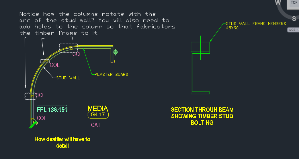
You need to rotate and orientate the beams so that its face runs with the stud wall face.
A stud wall cannot stand in the wall without some connection.
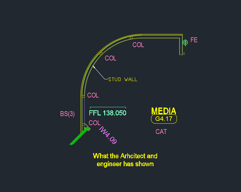
Please see the below diagram to show you how things are drawn in the engineering and architectural drawings:
What the engineer etc typically show. You must not shop draw to this exact design.
Now see below how you will need to detail the above design:
Shows how you will need to detail the design. Rotate the columns and also add bolt holes in the right places.
See here as well:
Showing the changes – clouded.
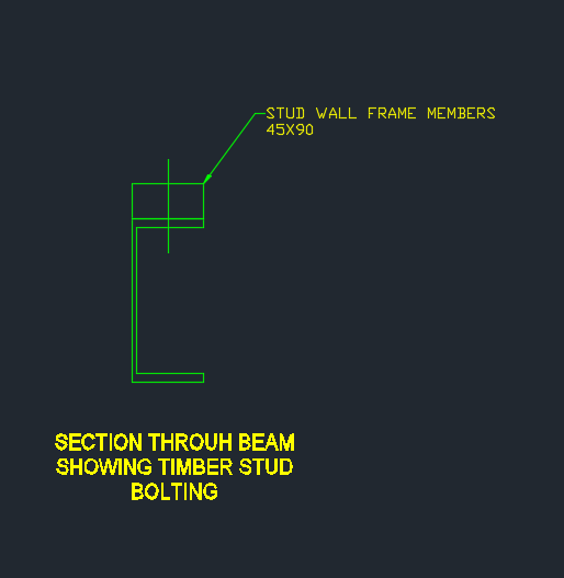
And a section view:
Shows a section view of the steel column and the stud.
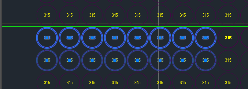
Overkill command was not working on these panel voids. Why do you think this is the case?
As you can see in the above picture, the top row of panel voids were doubled and in some cases tripled up. Obviously we don’t want this. Ordinarily, when such drawings are passed on to us we employ the overkill command. But for some reason it wasn’t working. And I couldn’t for the life of me figure it out.
That was until our lead Bubble Deck detailer suggested that the insertion points of the block references were not all on the same plane – some of them were in the Z plan – if that’s the case, then overkill would not recognise them as being the same block – and will allow them to continue to co-exist in the same drawing.
Solution:
Check that all similar items have similar insertion points. If they’re different – that’s why overkill might not be working for you.
Showing a sample revision cloud created in AutoCAD from the .net API.
It seems a common scenario that folks want certain polylines/curves etc to turn into a revision cloud.
How do we do this?
At the end of the day, the revision cloud is nothing but a polyline. You could roll your own polyline which handles the bulges and vertices so that it looks like a revision cloud – but that takes a lot of effort – the quick and dirty way of doing so involves creating the polyline programmatically and then calling an AutoCAD command on that Polyline.
There are a few ways you can call commands:
Using SendStringToExecute
Using Editor.Command();
I prefer the latter, because it is more flexible. SendStringToExecute operates after the command is completed – which may not suit your needs.
Here is a simple implementation – It should convert the circle into a RevisionCloud circle. Of course, you can tweak it to your own needs.