How to avoid grating and chequred plate errors being wrong , due to the view being wrong.
We have a copped a few of these errors where the chquered plate (or grating) was drawn upside down.
How to counter measure: add orientation part cut on the plate
The way to counter measure this error is to put an orientation part cut on the plate. Make sure on the part drawing the full lines of the cut is shown. Cut will have to be on the top surface of the plate and must not penetrate to the other side.
We want to dimension certain objects in the drawing.
First we need to identify the objects that we want to select. Since the Tekla Closed Open API doesn’t have much of a picker exposed, we would be forced to select the objects we need before running our command. We can do so with a pick first selection (to use the AutoCAD terminology).
(Unfortunately it’s not a block table record dictionary definition – but it kind of is :))
Some how or other all the block definitions associated with a drawing were not defined on layer zero – this is less than ideal. I guess it goes right up there with another instance I heard about: (i) about drawing everything in paper space, or layer zero, for example.
Accordingly, it feel to me to change all the block definitions. I could foresee that there might be some other requirement associated with changing all the block definitions, so I thought it apposite right now to employ the strategy pattern to solve the problem.
Here is the code in its entirety. I like using LINQ, it’s concise and efficient, so I beg the patience of those whose views differ:
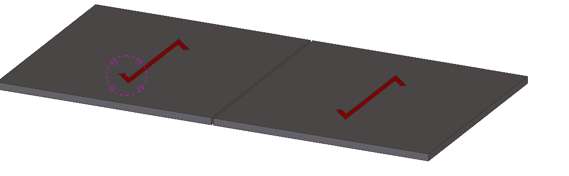
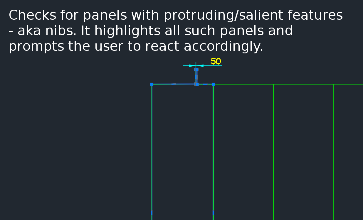
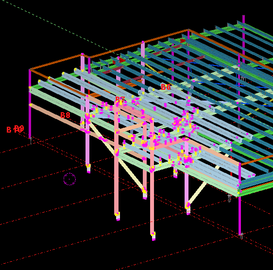
A gif showing how easy it is to check for nibs on bubble deck slabs using my command. There are certain panels which we have that have protruding elements – salient features. These can be problematic if they go to production unnoticed. Given there are entire teams of people doing things, it can be hard to track – people forget that they cannot draw a panel with such a dimension.
This is a plug in which enables one to easily identify all such panels with nibs like this:
There is a need to identify panels with protruding features because they could be problematic if fabricated.
Please see a generic time sheet solution below which I’ve developed – please use it for the time being before I develop a more robust solution.
Please fill this out honestly – 1 hour is one diligent hour of hard work. If you work slowly and take two hours – you can only write one hour on your time sheet. So it is in your interests to work as hard and as efficiently as possible. If you can think of a way of doing something faster and/or better, please go ahead and do so – while communicating this to your team leads and Koshy as well.
Tekla Structures is wanting features in detailing plate work. Here is a video showing how Advance Steel handles Plate work. This type of cuts are not possible with Tekla Structures. I think it is mainly because of the data structure of Tekla. Of late Tekla has changed their data structure to deal with these type of situations. But I have not seen any videos from them.
It’s not easy to find which bolt has a tolerance of 10 when you have 1000s of them in your model. You can really only do that type of thing with a tool.
This is a repost from our sister site – I needn’t repeat it here, but it’s something that I’ve worked on, and which we hope to utilize to a greater degree when working with Tekla. Anyways, you can get the full blog post if you click this link here. Thank you for stopping by.
We can easily select objects as an input – objects which was can iterate over and apply a series of operations or checks out. But how do we return a selection of objects back to the user?
Background: What are we trying to do?
We have programmatically identified some model objects that we want to select in the model – to attract attention to the user and to allow her to easily identify all such objects. In this particular case we will be creating some beams. And then, we will select those beams in the model. Here is a code snippet to get you started:
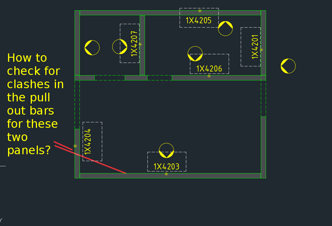
How are you going to ensure that the starter bars do not clash? You’ve got 1000s of panels to detail and a dozen detailers working on different projects. How are you going to manage this?
What is the problem?
Consider this situation – you’re got a marking plan in front of you. You want to make sure that the ferrules in corner panels do not clash. How are you going to do that?
How would you solve the problem?
You’d have to find the corner panels, and then go to the appropriate drawing – both of them mind you – and you’d have to make sure that they are at different heights. That can get very tedious and it’s very time consuming, and more than likely, you’ll make some mistakes – because the panel elevations might not be adjacent to each other.
It’s not the easiest thing to see and compare in AutoCAD.
What is a better way to solve the problem?
But now you have a tool which allows you to easily compare the heights of the ferrules in two panels, straight from the marking plan.
There’s a lot of code and logic which goes with this. Perhaps I will outline it in another blog post.
Code Synopsis
For a very, very brief description of the overall route used, you can check out the code synopsis from my sister blog here. There I post the base class and interfaces used to derive the result – but have excluded all the implementation details.
Video Demonstration
Here is the video demonstration – and yet another example of the type of technologies and innovations you will have at your disposal if you work with us: