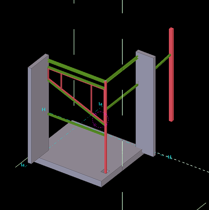
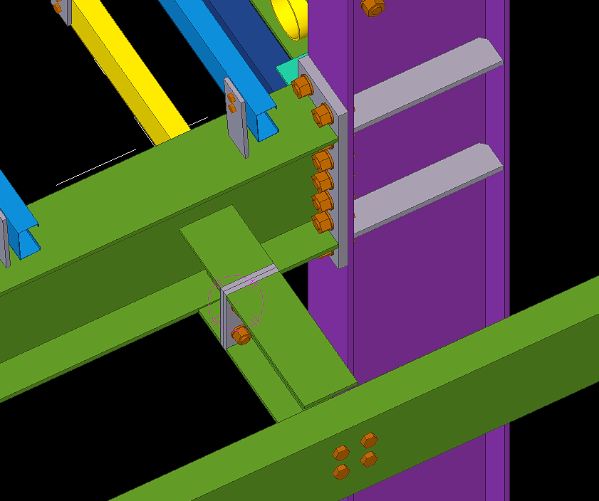
When modelling Steel members with existing steel always be aware to get the site measurement to avoid conflicts during the erection of drawings.
Blog by Bharath – Tek1.
Visit www.tek1.com.au for further enquiries.
When modelling Steel members with existing steel always be aware to get the site measurement to avoid conflicts during the erection of drawings.
Blog by Bharath – Tek1.
Visit www.tek1.com.au for further enquiries.


Blog by Bharath – Tek1.
Visit www.tek1.com.au for further enquiries.


Blog by Bharath – Tek1.
Visit www.tek1.com.au for further enquiries.
When modelling big projects. Do not waste time in modelling all the entities provided in the sample drawing this could waste lot of man hours. Draw only the members that are attached or could affect the steel members.
By following this we could save lot of man hours and also maintain the accuracy with faster submission of projects.


Blog by Bharath – Tek1.
Visit www.tek1.com.au for further enquiries.
The standard truck dimension for transporting steel members in Australia is 12m x 2m x 2m. Any member greater in length has to be informed in prior to avoid extra charges that occur in transportation.
Sometimes when we encounter a member more than 12m long we can mark-up and inform the Project manager regarding this see below snip as an example.
We have also a used a custom profile in this model based on client requirements which deviates from the standard profile. See below the snip of the profile used.


Blog by Bharath – Tek1.
Visit www.tek1.com.au for further enquiries.


Blog by Bharath – Tek1.
Visit www.tek1.com.au for further enquiries.
Why Bim 360 Docs?
Bim 360 is Construction project management software created by Autodesk. The main intent of using Bim 360 Docs will resolve the following thing
Steps for Creating Project in Bim 360 Docs (Before these steps, log in to the Autodesk account you created in the Bim 360 and select the docs. Click “try now” after that you will see the images shown below
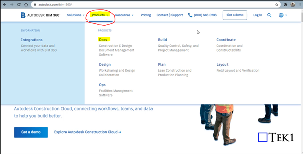
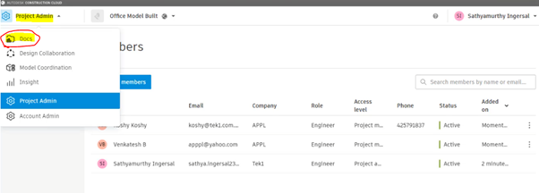
Step 1: Select the “Docs” Dropdown box on the top left corner of the Bim 360 Docs
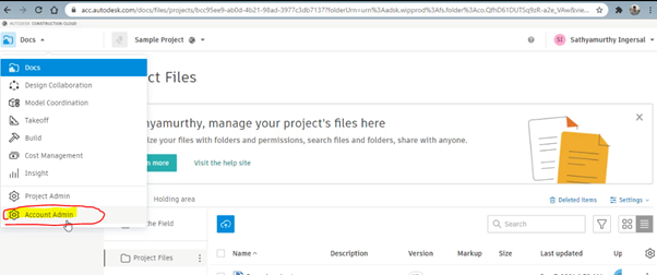
Step 2: Click on the Account Admin to create a new project
Step 3: Click on to “ Create Project”
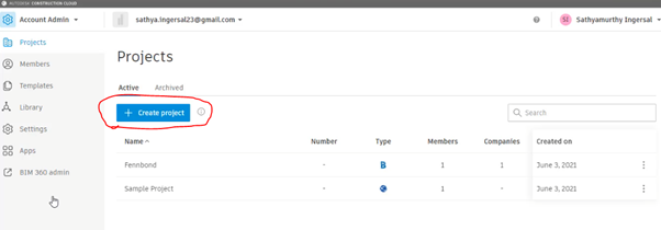
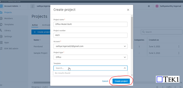
Step 4: Fill the Project Details and Particulars with your Autodesk Email ID and click Create Project
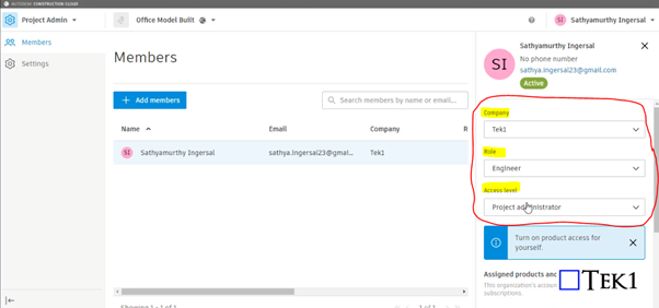
Step 5: Provide your information such as role, access level, and organization on the right-hand side
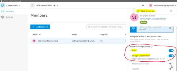
Step 6: Please Turn on the products to be used by moving the scroll down. So that Turned on feature can be accessed as shown in Step 10
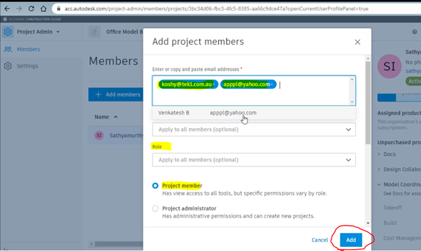
Step 7: Click on to Add member to assign the members who are going to involve and access the files in this project
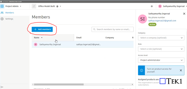
Step 8: Assign the members by adding their Autodesk email with organization name and their role and select as project member and click Add
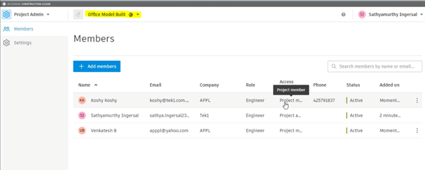
Step 9: After adding the member you can see their active status and details under the project we assigned
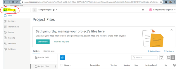
Step 10: As we turned on the following highlighted things in step 6. So that now we can access the following by Selecting the Dropdown and click on the docs to upload the file
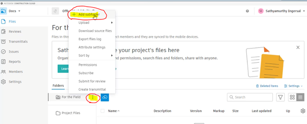
Step 11: To create Subfoler and folder click on to the highlighted below and select Add subfolder
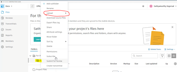
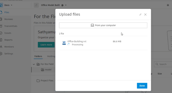
Step 12: After creating and naming the folder right-click to it and click on the upload and file. then drag the file and start upload
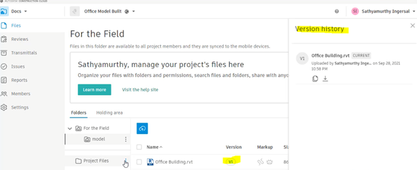
Step 13: The file with its details and version, Mark-ups status will be displayed once the above steps are done
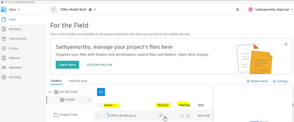
By clicking on to version you can review the history of the file from start to upload till revised. The file model can be review online itself by clicking on Filename
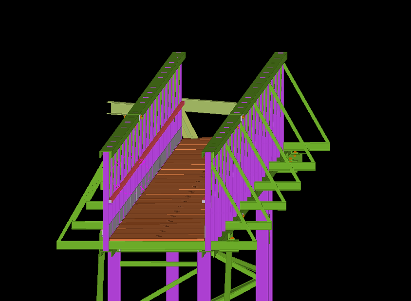
Foyer-Stair is one of the simple structure detailed by Tek1.
Find below list of short notes for modeling and detailing stair.
Two common code books followed are:
AS1428 – Commercial Structure
AS1657 – Industrial Structure
Also keep a note on the nosing point must fall on same slope to stair.
The thread and riser must be of same length and height else could cause the user to stumble when accessing the stair.


Blog by Bharath – Tek1.
Visit www.tek1.com.au for further enquiries.
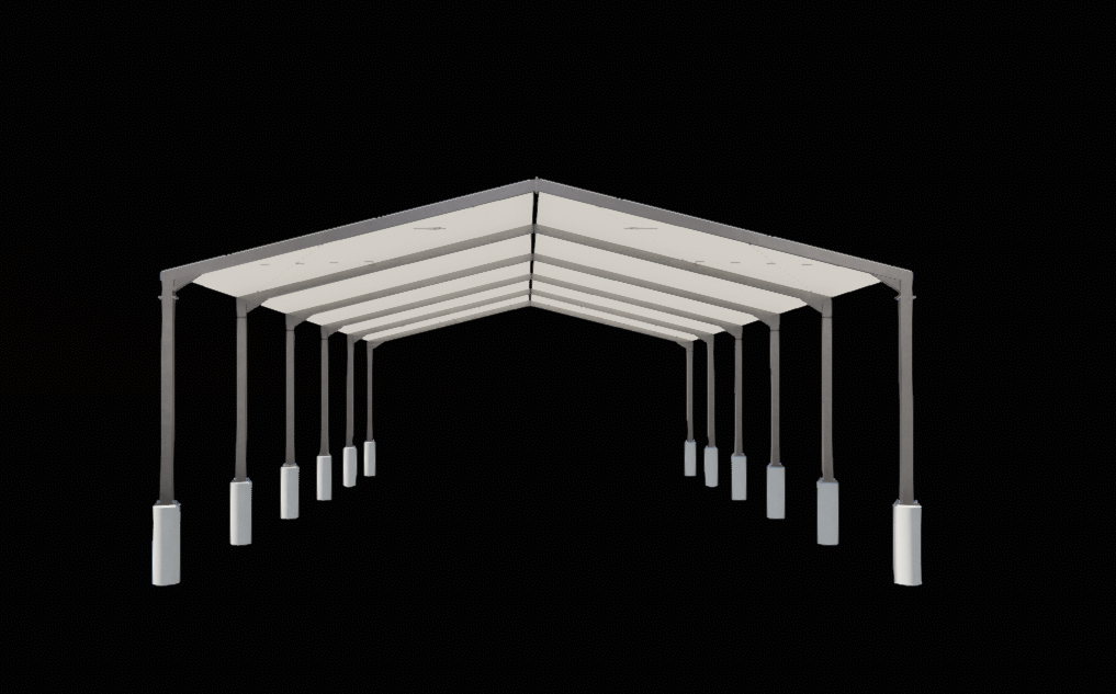
Richmond Cinemas is one of the simple structure detailed by Tek1.
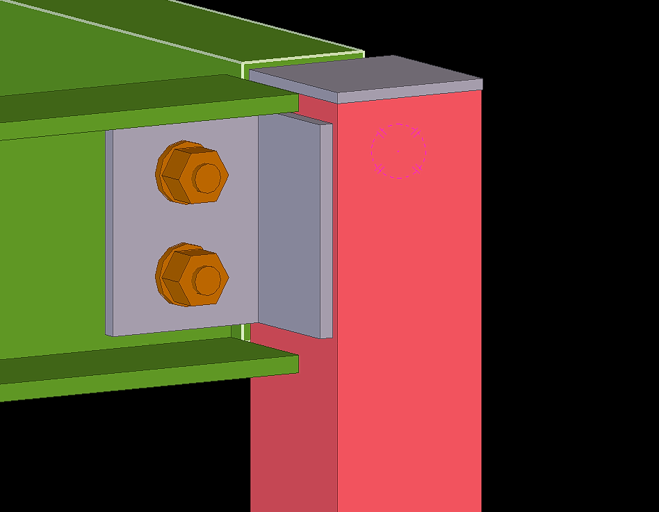
Tekla could deliver you the design with highest accuracy possible. Any error due to fabrication or in members effected by external factors like weather etc. could be resolved by giving a tolerance to the structural members. This could also save the Erector during erection, saving a lot of time and money resolving this issue. Too much tolerance on members like plate could also have adverse effect.


Blog by Bharath – Tek1.
Visit www.tek1.com.au for further enquiries.