If you are dealing with the Tekla API, you have to watch out for the following gotchas:
Anamolies in the way Tekla handles Rotations from Tek1 on Vimeo.
If you are dealing with the Tekla API, you have to watch out for the following gotchas:
Anamolies in the way Tekla handles Rotations from Tek1 on Vimeo.
We are looking for a business partner of a commission sales agent in the USA We have already set up a shelf company in Nevada.
We are looking for a business partner who can bring in business in precast, steel and rebar detailing
Our current status.
Steel Detailing team – 35 strong – Very highly skilled and brilliant. Our recruitment process weeds out pretenders and people who run around with an engineering degree certificate but knows nothing about engineering.
We have an unmatched training program. Certainly not matched anywhere in India. I can tell with reasonable confidence that even elsewhere in the world, it will be extremely expensive to provide the quality and type of training we provide. Hence the people who work on projects know what they are doing.
No pirate software
We make sure we don’t use any pirated software of any sort. Hence no project will be in jeopardy because of anyone coming and shutting us down.
Precast Detailing team
25 strong precast detailing team – Tool used is Autocad. Again highly experienced.
Rebar detailing team – Non-existent right now
We are developing rebar tools based on an IntelliCAD system. It will be 6 months before we develop this tool to a state where it can be used internally with efficiency. At that point, we will recruit a few experienced rebar detailers and then train at least 10 fresh guys under them.
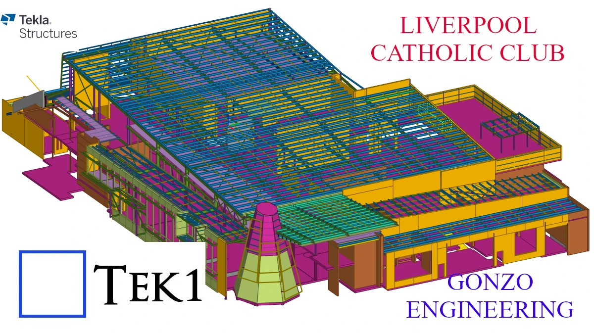
This is the first project we have detailed for Gonzo Engineering many years back.
Gonzo is still one of our top clients.
Many sydney fabricators have put their trust to use tek1 for their major projects
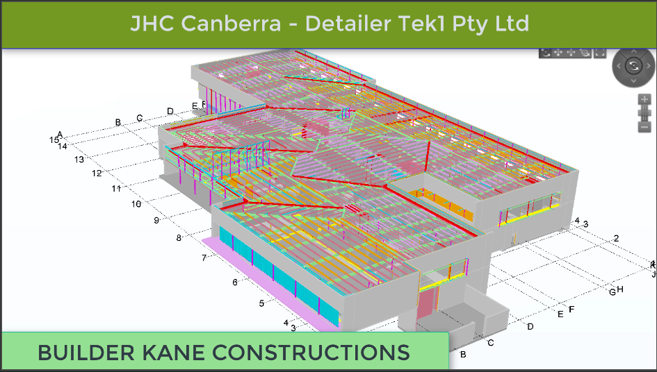
View this article to see the Emu In the sky, detailed by Tek1 for a major Sydney fabricator
Tek1 has completed this rather complicated project with support from a brilliant detailing team. The project was complex demanded a very high level of detailing knowledge. We have put our best guys on this job. They have done wonderfully well in completing this project without a hitch. The builder in this instance was Kane Constructions. The fabricator Gonzo engineering.
You may visit our Services page for more information for the type of work we doe
WORKING WITH EXISTING STEEL
We continue our blog post series.
Consider the details below. It’s time for a pop-quiz: what issues can you see here?
The structural engineer provided the gusset connections with a 10mm erection clearance (see the snap above). But as a steel detailer we must provide a standard min erection clearance for all the connections. (We shouldn’t follow blinding, but we have to think before using their details.).
We must need to provide 15mm min as erection clearance. (because the weld takes up to 8mm). If we give 10mm clearance then the connection plate will hit the weld. It makes erection issue at site. Erection issues are costly and time consuming: resources will need to be occupied on site. Labour is expensive in Australia – and time is expensive anywhere. These sorts of issues need to be absolutely avoided with good detailing practices.
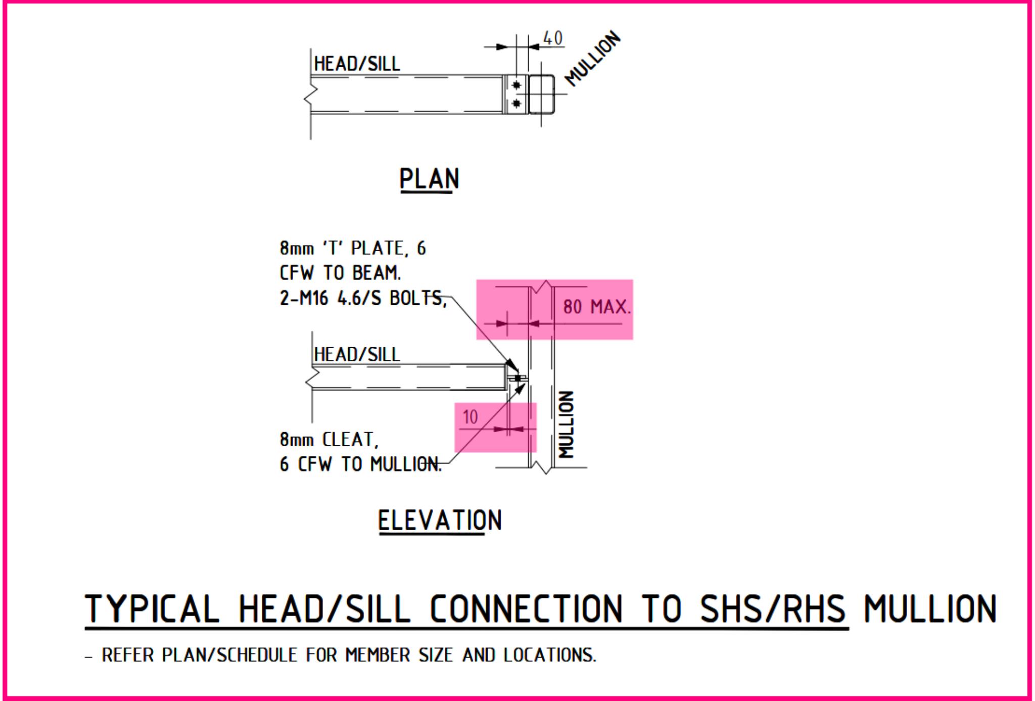
Please refer to the snap below snap: it shows an example of site issues due to insufficient erection clearance. Also we have attached our sketch shows our standard typ connection details.
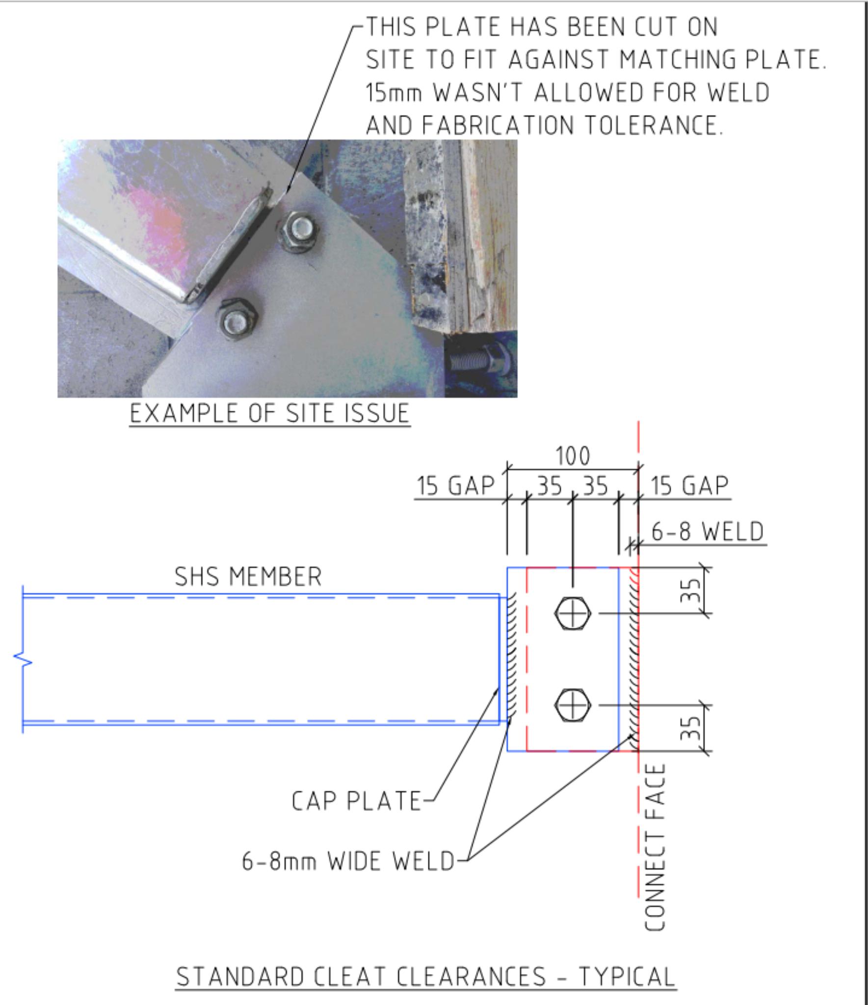
What further issues can you see above?
Answer: The plates are of a non-standard size. This means that the fabricator needs to custom make a plate. That involves extra labour, for something that is entirely unnecessary. Plates need to be custom made only when absolutely required.
Detailed Instructions:
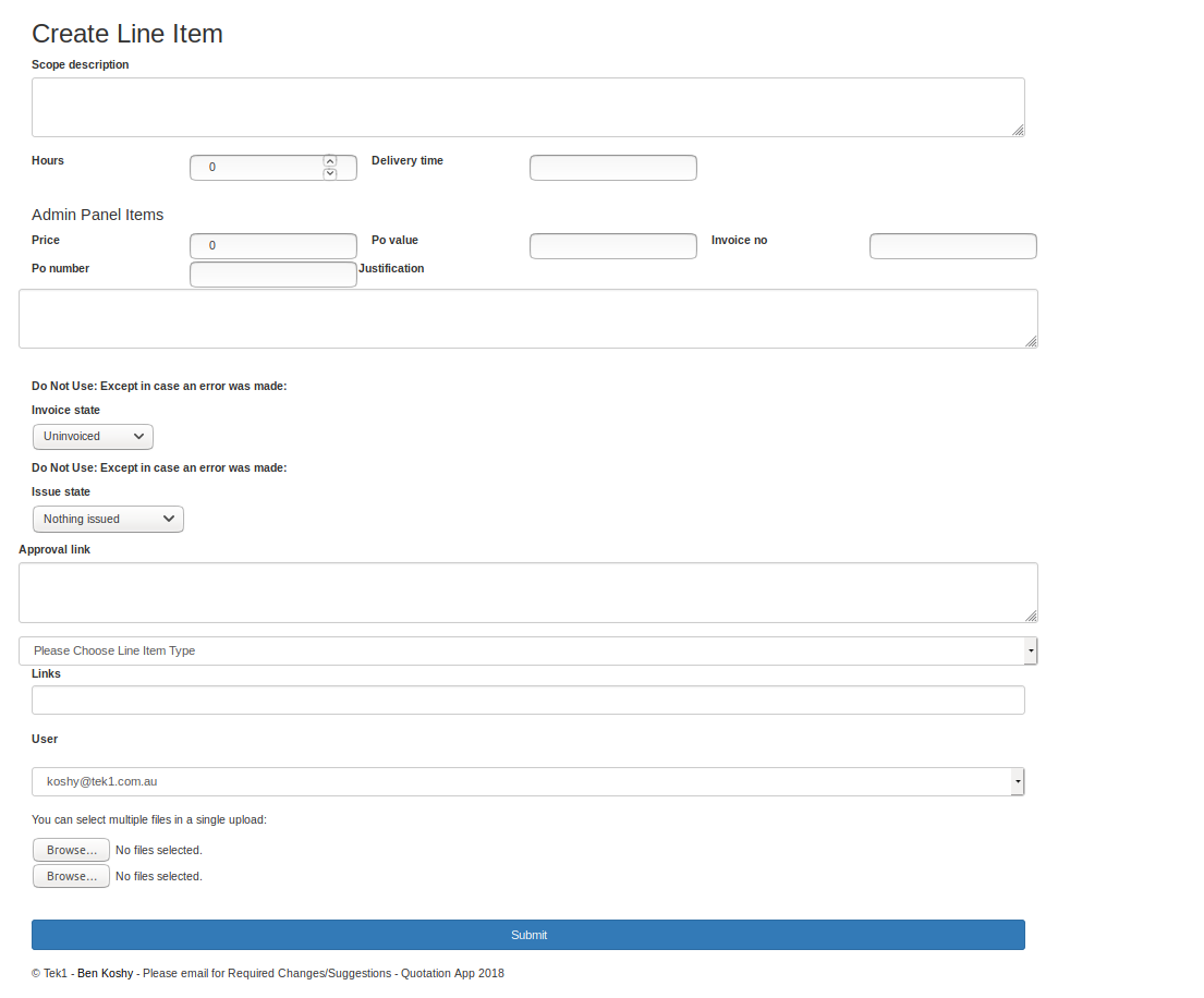
We have casual jobs for styling forms and reports on Ruby on Rails platform
If you have experience as web developer Ruby on Rails experience, with bootstrap, we have some amount of work available for the next 6 months.
Please contact us so that we can discuss this. This is not a full time position. It is a casual position at this stage.
You must have a good grasp of rails running on Ubuntu (Not Windows) and must know bootstrap pretty well.
Kudos to the engineers and architects on this project. Their support had been brilliant. We have never come across another engineer or architect who had been so prompt in resolving issues on this project. We were able to complete this project very quickly mainly because of the super support i
n resolving RFIs from the engineers architect and the builder. The builder is Kane Constructions.
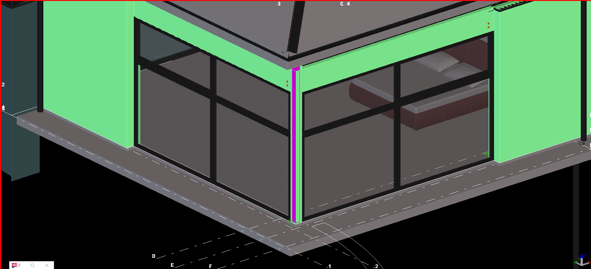
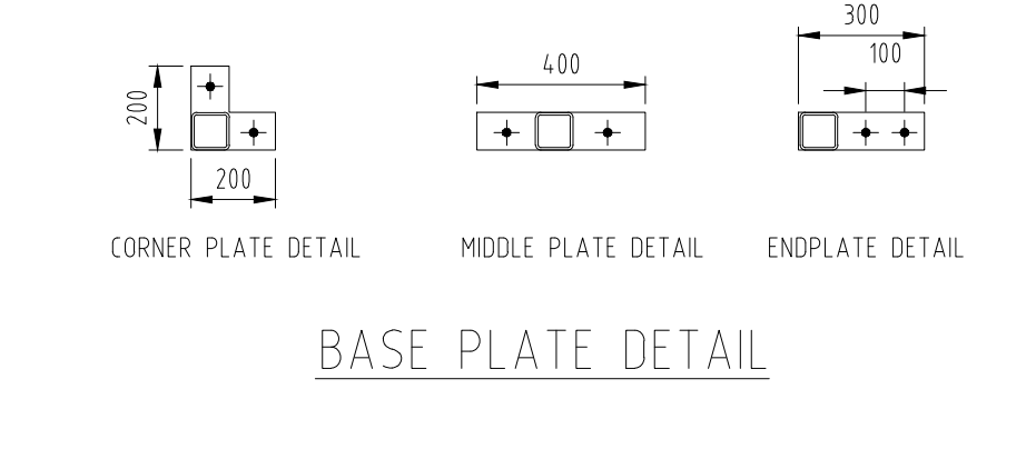
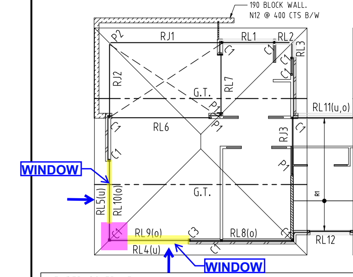
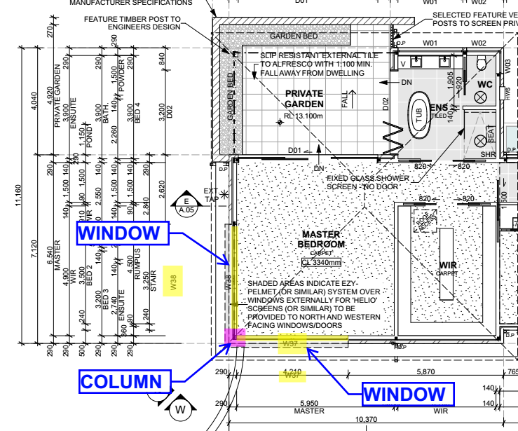
The design drawing requested one column at the wall corner. Also both sides of the corner wall had windows that stand from the finished floor level.
In this instance, we couldn’t follow the structural engineer’s recommended base plate details, because the base plate and anchors will interfere with the window clear open area.
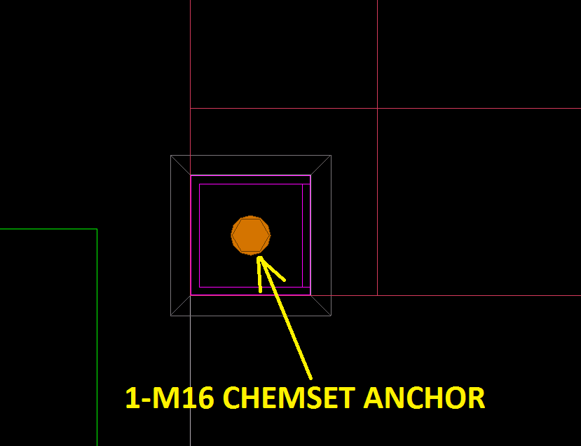
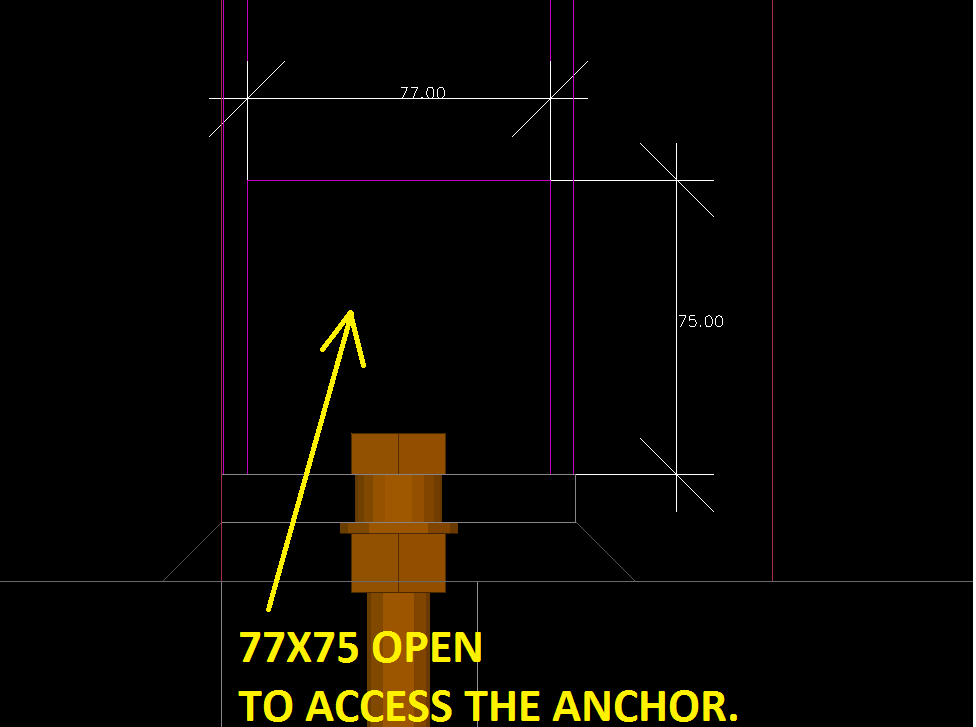
So we suggested the single anchor at the center of the column and make with one access hole in the column web.
The client accepted our suggestions for this case. See the attached snap to understand the issue, and try to spot the problem, and try to solve the problem as if you were facing it for the first time.
See the structural design drawings:
The architectural design:
The Proposed Solution: