Please see a generic time sheet solution below which I’ve developed – please use it for the time being before I develop a more robust solution.
Please fill this out honestly – 1 hour is one diligent hour of hard work. If you work slowly and take two hours – you can only write one hour on your time sheet. So it is in your interests to work as hard and as efficiently as possible. If you can think of a way of doing something faster and/or better, please go ahead and do so – while communicating this to your team leads and Koshy as well.
Tekla Structures is wanting features in detailing plate work. Here is a video showing how Advance Steel handles Plate work. This type of cuts are not possible with Tekla Structures. I think it is mainly because of the data structure of Tekla. Of late Tekla has changed their data structure to deal with these type of situations. But I have not seen any videos from them.
It’s not easy to find which bolt has a tolerance of 10 when you have 1000s of them in your model. You can really only do that type of thing with a tool.
This is a repost from our sister site – I needn’t repeat it here, but it’s something that I’ve worked on, and which we hope to utilize to a greater degree when working with Tekla. Anyways, you can get the full blog post if you click this link here. Thank you for stopping by.
We can easily select objects as an input – objects which was can iterate over and apply a series of operations or checks out. But how do we return a selection of objects back to the user?
Background: What are we trying to do?
We have programmatically identified some model objects that we want to select in the model – to attract attention to the user and to allow her to easily identify all such objects. In this particular case we will be creating some beams. And then, we will select those beams in the model. Here is a code snippet to get you started:
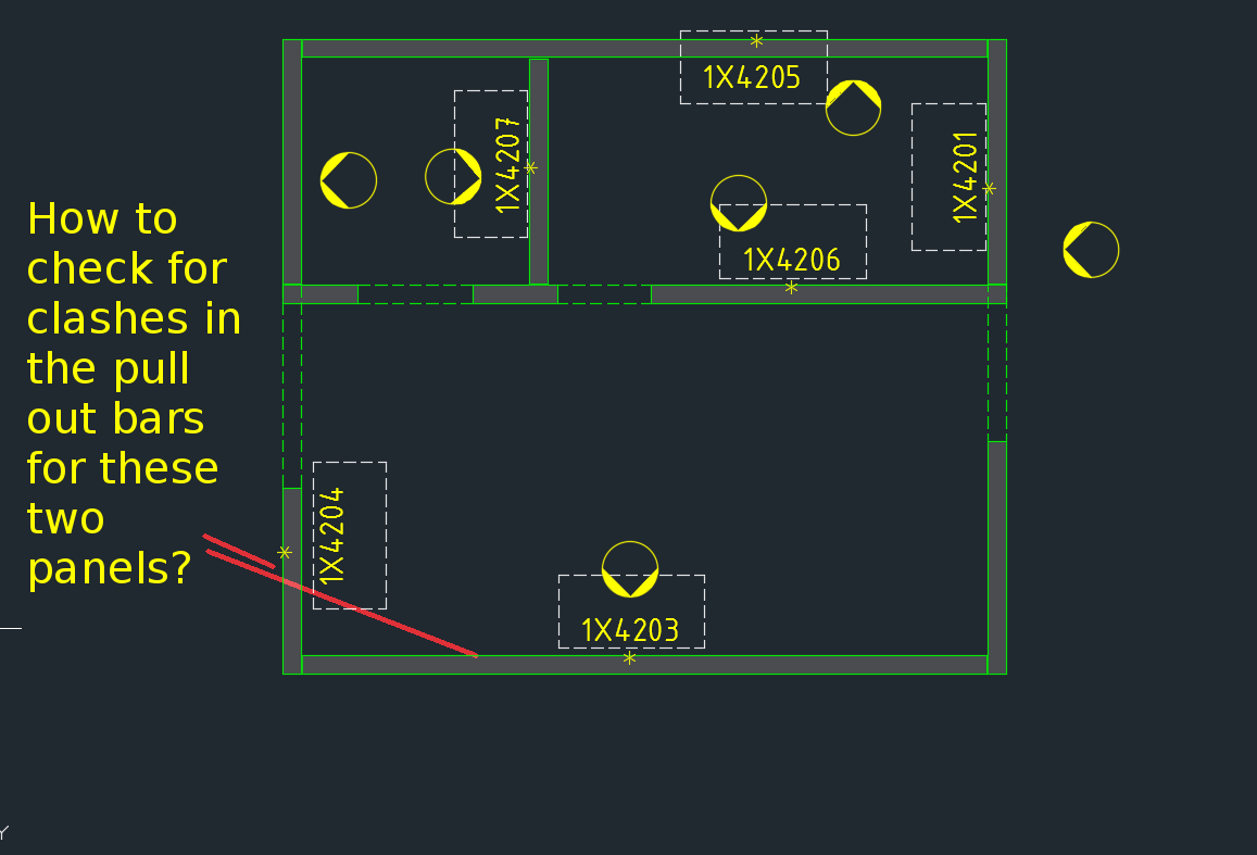
How are you going to ensure that the starter bars do not clash? You’ve got 1000s of panels to detail and a dozen detailers working on different projects. How are you going to manage this?
What is the problem?
Consider this situation – you’re got a marking plan in front of you. You want to make sure that the ferrules in corner panels do not clash. How are you going to do that?
How would you solve the problem?
You’d have to find the corner panels, and then go to the appropriate drawing – both of them mind you – and you’d have to make sure that they are at different heights. That can get very tedious and it’s very time consuming, and more than likely, you’ll make some mistakes – because the panel elevations might not be adjacent to each other.
It’s not the easiest thing to see and compare in AutoCAD.
What is a better way to solve the problem?
But now you have a tool which allows you to easily compare the heights of the ferrules in two panels, straight from the marking plan.
There’s a lot of code and logic which goes with this. Perhaps I will outline it in another blog post.
Code Synopsis
For a very, very brief description of the overall route used, you can check out the code synopsis from my sister blog here. There I post the base class and interfaces used to derive the result – but have excluded all the implementation details.
Video Demonstration
Here is the video demonstration – and yet another example of the type of technologies and innovations you will have at your disposal if you work with us:
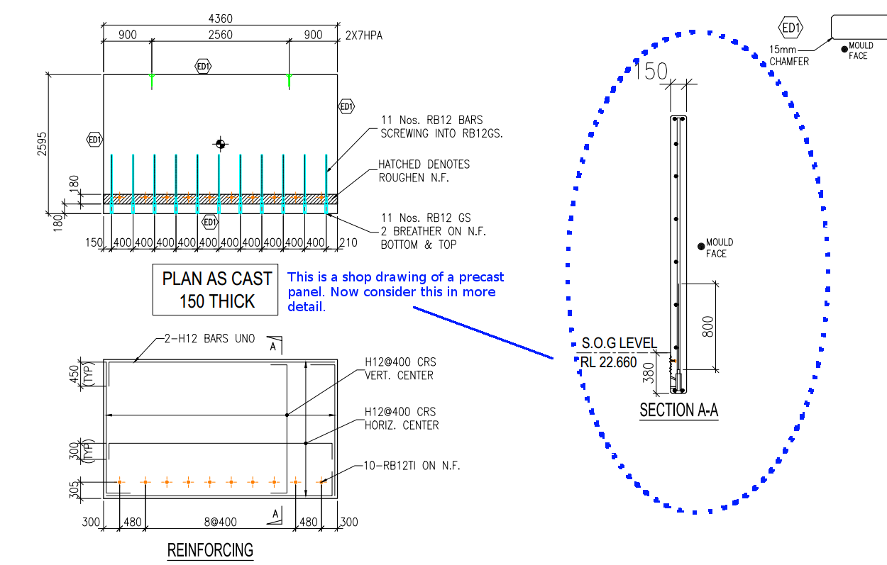
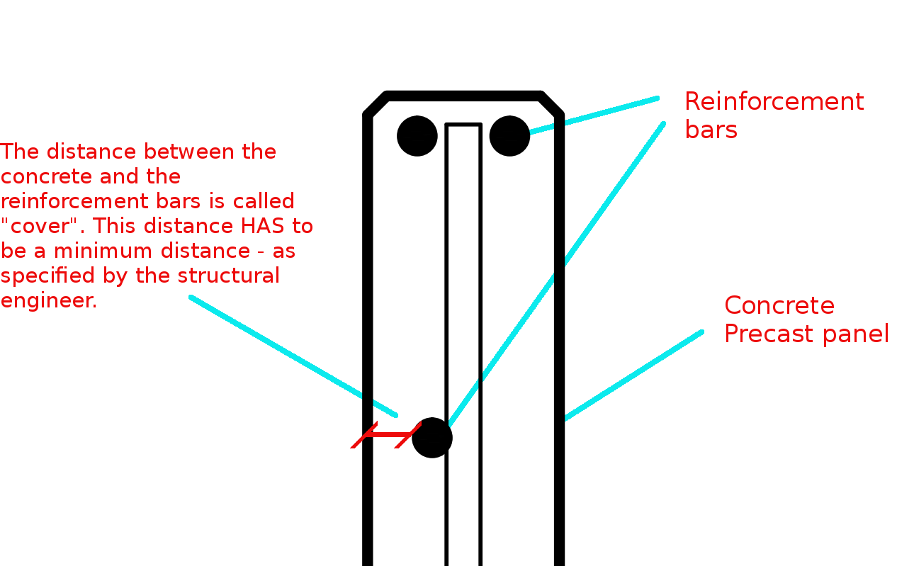
Cover refers to the distance between the outside of a concrete structure and the reinforcement. Perhaps see this from the diagram below:
This is a general overview. Now let us zoom in and see more detail.
The distance between the concrete and the reinforcement bars is called “cover”. This distance has to be a minimum distance – as specified by the structural engineer.
You need to have a minimum cover:
There needs to be a minimal distance between the reinforcement bar and the outside of the panel.
Why do you need this?
Reduces Corrosion
Having a decent amount of cover reduces the rate of the corrosion of those reinforcement bars. If you have only 5 mm of cover – if the bar is literally just below the surface of the concrete, then that reinforcement is going to corrode away very quickly – especially if you are close to the sea. This means that the concrete will lose its strength very quickly, and a catastrophic failure might be on the cards. That’s why it is very important that the concrete does indeed have some minimal cover.
To Improve the Structural Integrity of the Concrete:
If you have the reinforcement bar too close to the concrete, then the structural integrity of the structure will be somewhat compromised.
Fire Protection:
If at all there is a fire, you don’t want the reinforcement bars igniting. If it does then the fire is sure to blaze out of control. That’s another reason why it’s very important that the bars some minimal distance away from the surface of the concrete. That will better enable the structure to remain in tact if at all there is a fire.
A Response to a Reader’s Question:
A diagram attached with a question from a reader.
“(Q1) It appears that one of the lapped bar is bent while the other isn’t. Or is it just a drawing convention problem?”
(Q2) I don’t get why the lapped bars have to be positioned differently when placed on the top vs at the bottom in order to ensure that the concrete thickness will not reduce, as stated in the figure. My thought is that both positioning ways occupy the same volume.
The answer to this question is best understood by studying the below diagrams:
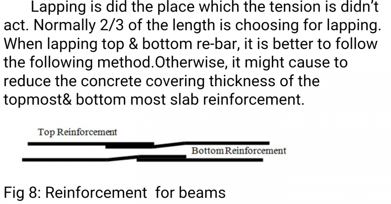
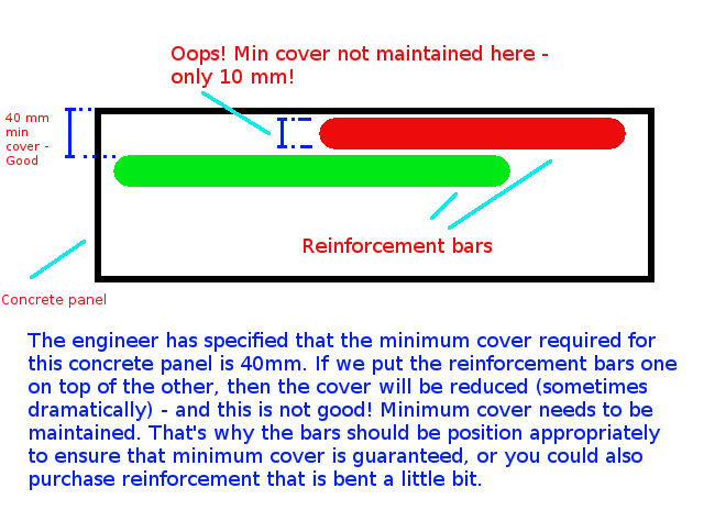
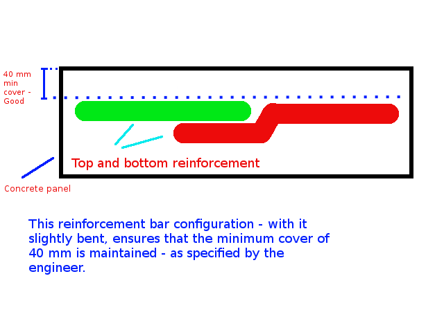
Caption: The engineer has specified that the minimum cover required for this concrete panel is 40mm. If we put the reinforcement bars one on top of the other, then the cover will be reduced (sometimes dramatically) – and this is not good! Minimum cover needs to be maintained. That’s why the bars should be position appropriately to ensure that minimum cover is guaranteed, or you could also purchase reinforcement that is bent a little bit.Caption: This reinforcement configuration – with the reo slightly bent, ensures that the minimum cover (in this case 40mm) is maintained – as specified by the engineer.
The Answers to the Questions
(A1) When I draw reinforcement, I do not add a lot of the essential details which are assumed to be standard workshop practice. We are required to maintain a minimum cover. The diagram you have posted above is an example of what actually occurs in practice (but is almost never drawn that way). The reason it is bent is to ensure that the minimum cover requirements are not compromised.
(A2) That is absolutely correct – the panel’s thickness will not be reduced, but the thickness of the cover will change, depending on how one places the “reo” (reinforcement) rods.
If you’ve run AcCoreConsole and can’t bring back the normal user interface, just remember this trick.
So I’ve just managed to run AcCoreConsole – some script. And it’s changed some settings. And now when I open regular AutoCAD, when I type in netload – it seems that I’ve lost the ability to open/select things using the user interface. Now I have to manually type out long file names into the command line which is the height of tedium.
Why did it happen?
It happened because we were not meticulous in the running of our AcCoreConsole scripts. We should be sure to ensure that we save settings properly so that when users use the regular AutoCAD program, they don’t have to reconfigure the entire environment away from what works well for AcCoreConsole, back to what they are normally used to.
How to fix the problem immediately
You can file the problem by typing in:
That should change those settings back to normal.
How to avoid the problem in your script file
Don’t forget to return it to the original settings: anything beginning in a semi-colon is a comment and will not be executed.
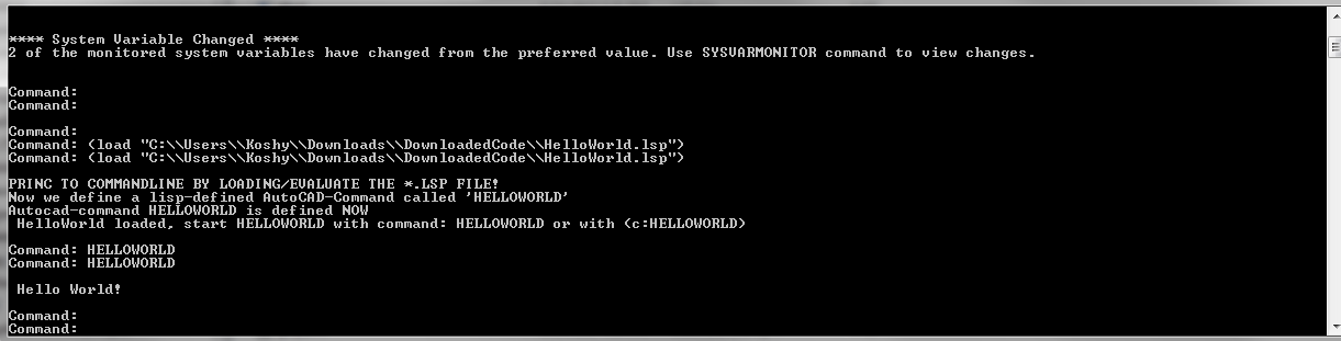
A commenter had some trouble loading the files. So perhaps the AcCoreConsole is confusing people. So here is a post which will hopefully clarify how to do it.
It’s quite simple:
Have the LISP file ready.
Load the lisp file
Call the command.
It works exactly the same as in AutoCAD – the UI version. But remember you cannot call any commands which make use of Windows forms or WPF. It is strictly command line only. So things like APPLOAD are not going to be very effective in the AcCoreConsole.
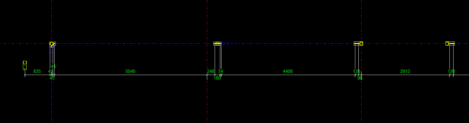
When marked to all grid lines, this makes it easy for the folks on the floor to mark out. Don’t make it hard for them!
What is the task at hand?
So I get some phone calls the other day – people complaining. They want changes. Yet again! Why can’t these people make up their minds! That means I have to get off Facebook, go back to my code – which I hopefully haven’t forgotten, and I have to try and make their changes fit in, with the least amount of trouble.
What did they want this time?
They wanted to dimension bolts not just to one grid line, but to every single one. Ok that’s fine. How am I going to select all parallel gridlines, given an input of just one gridline?
First I need the input Gridline. This is given. We have the input gridline because we’ve asked the user to select a relevant gridline.
We need to get the actual grid, using that grid line.
We need to get all pertinent gridlines using the grid – we want to get only the gridlines that are parallel with our originally selected gridline.
Using those filtered gridline points, we need to extract out a pertinent reference point and add that to the set of points used to create the dimensions.
1. The Input Gridline
This has been obtained by selection.
2. Getting the Actual Grid
3. Getting Pertinent Gridlines
Now we extract the relevant points given the above information.
This is the final result:
4. Create the dimensions
We’ve got the bolt dimension (previous post). We have some grid line dimensions (see above code). Add the above points to the bolt positions and then create those dimensions as outlined in the previous post. Voila! We are finished! Now back to WoW!