| Street Address | 34 JARDINE STREET FAIRY MEADOW |
| State | NSE |
| Country | AUSTRALIA |
| Engineer | |
| Architect | |
| Modeler | DHILEEPAN |
Author: Dhileepan
-
Woonona
-
Adding & Sharing New Material To Tekla
In this blog, we will look at how to create and share new materials in a Tekla model. By default, Tekla comes with a predefined list of materials stored in the system drive (C drive). However, in many projects, we often need to add custom materials based on project requirements. To add a new material, go to the Menu at the top left corner, navigate to Catalogs, and then open the Material Catalog. From there, select an existing material, right click & selct “Add Grade,” rename it as required, and assign the appropriate density. Once saved, the new material will be available in the model.
When sharing the model, especially using the db1 file to reduce file size, the newly added materials may not be available to the recipient. This is because custom materials are stored separately. To ensure the other user can access the same materials, you need to share the file named “matdb.bin” from the model folder. This file is created only when new materials are added and must be included along with the db1 file.
Alternatively, there is another method to share materials. In the Material Catalog, you can use the “Export” option available at the bottom to save the material data as a separate file. This file can then be shared, and the recipient can import it into their Material Catalog to access the same materials.
Watch the video below for a step-by-step demonstration of this process.
-
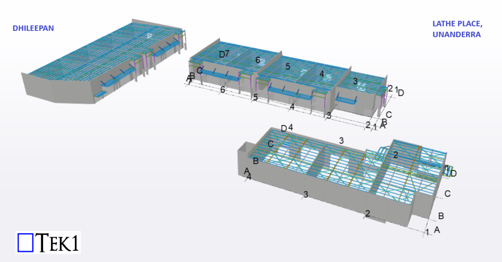
Lathe Place, Unanderra
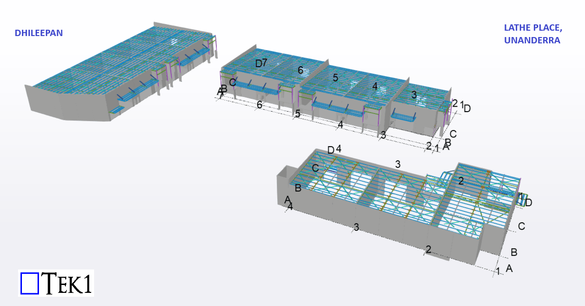
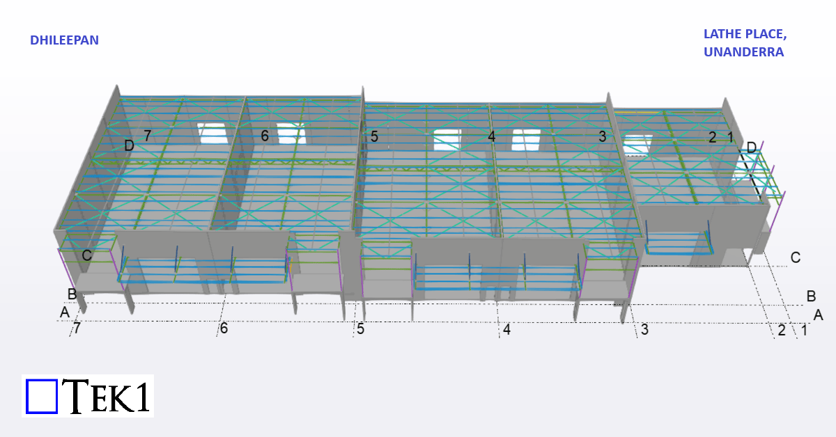
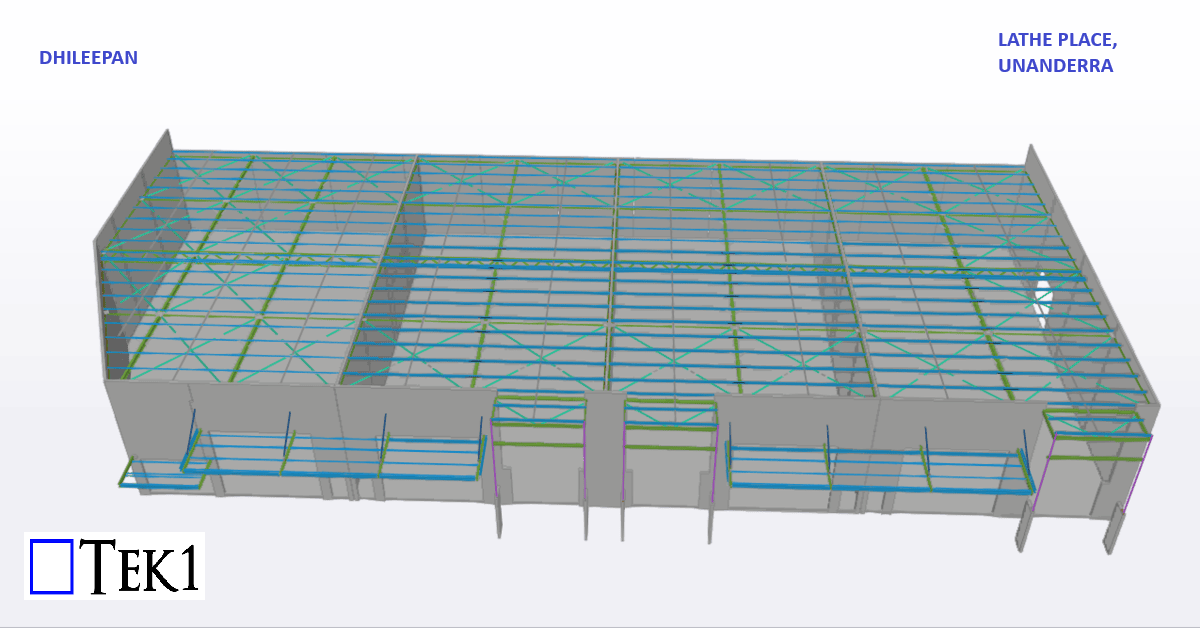
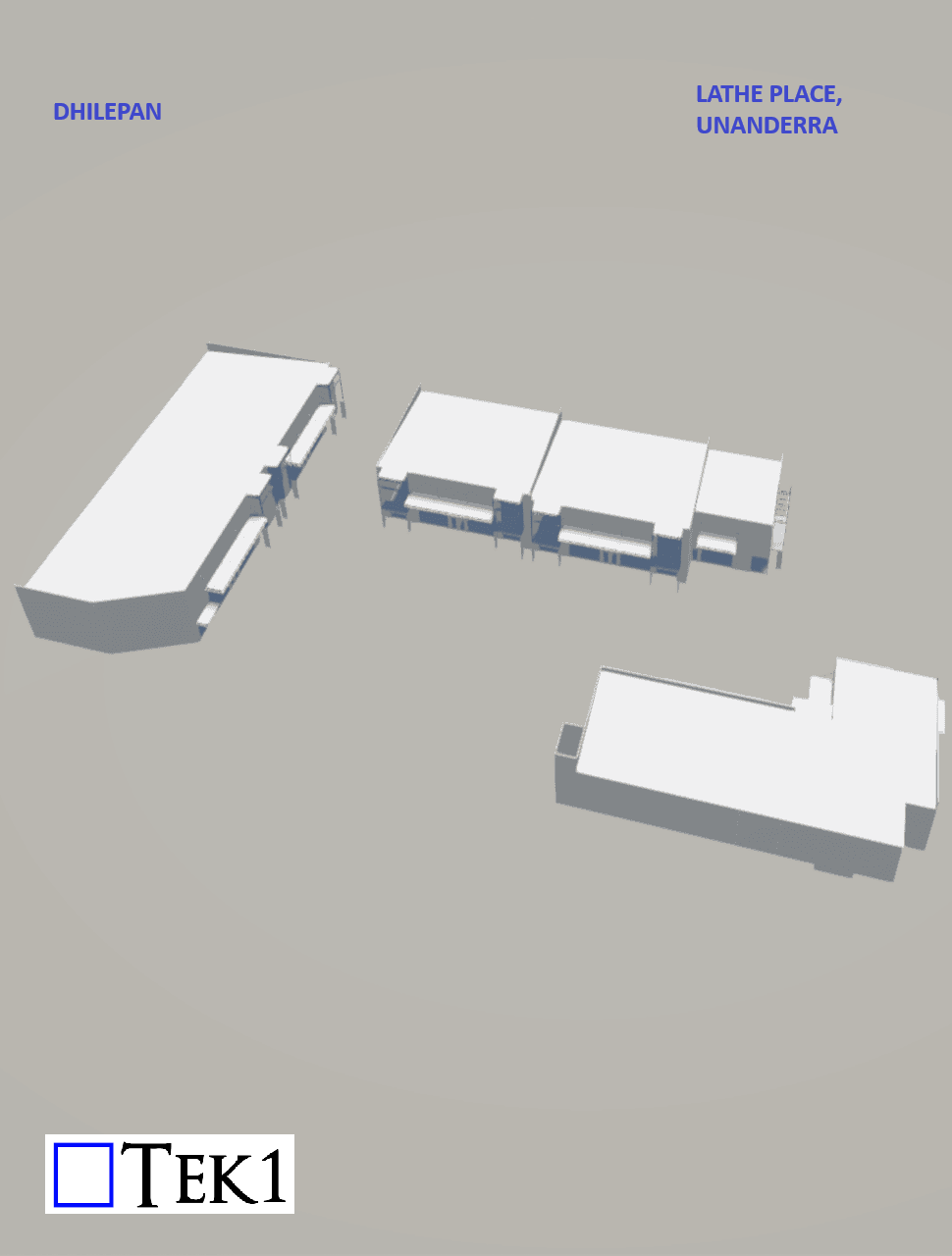
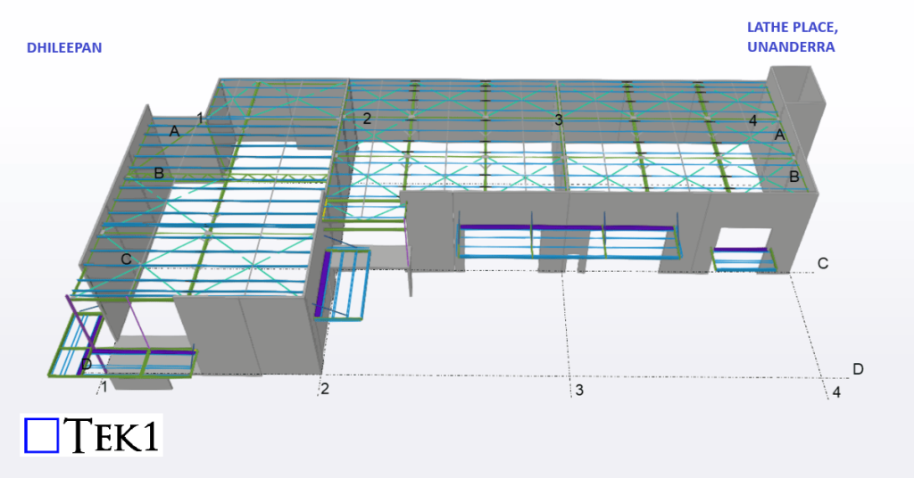
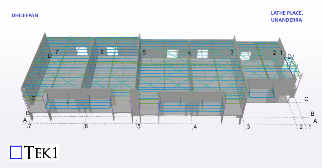
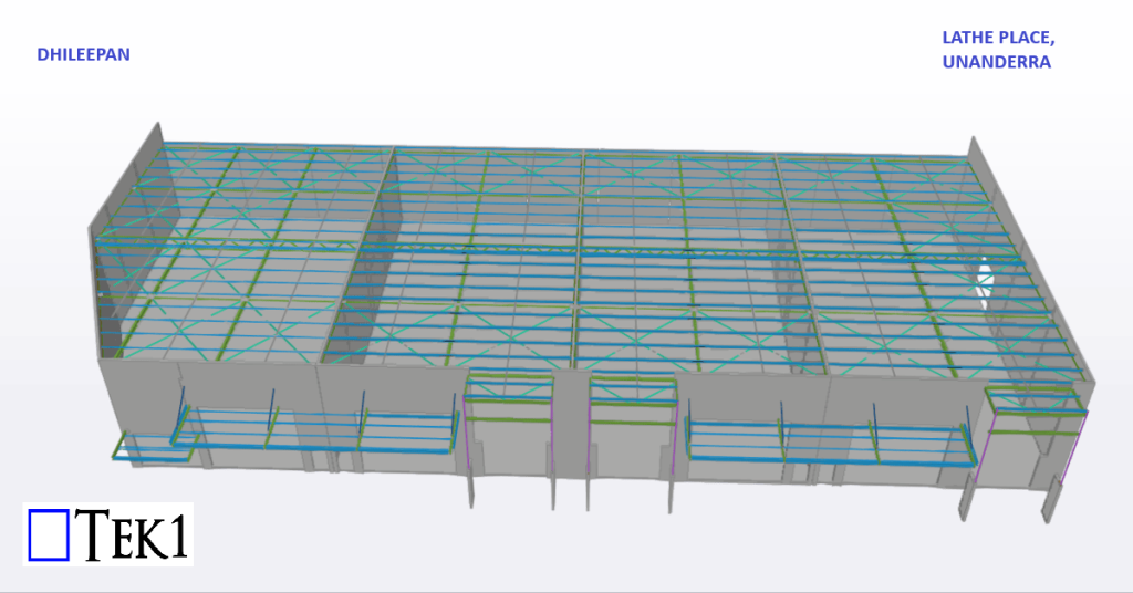
This blog provides an overview of the modelling and detailing work completed for the Lathe place project at Unanderra.
This industrial development has 3 block comprising of 12 units. Each block has precast panels all around with steel roof & awnings.
-
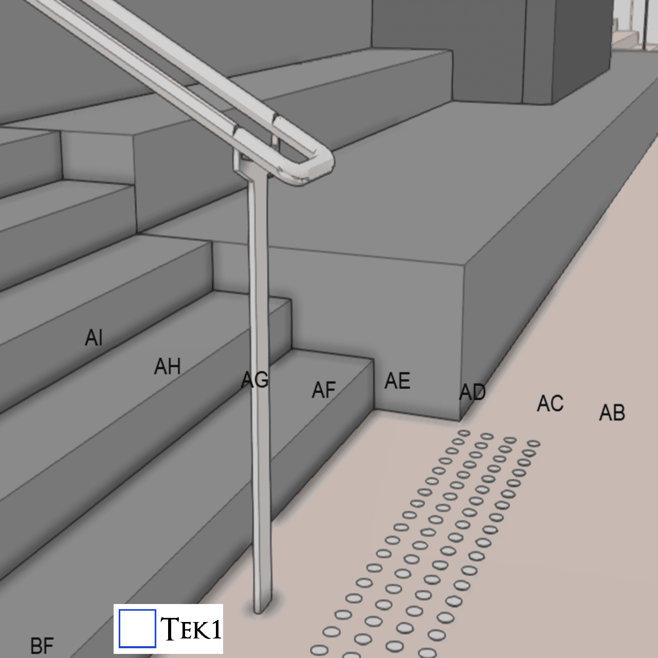
When Accessibility Meets Practical Design: A Performance Solution at Moore Park
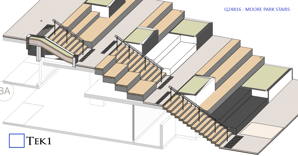
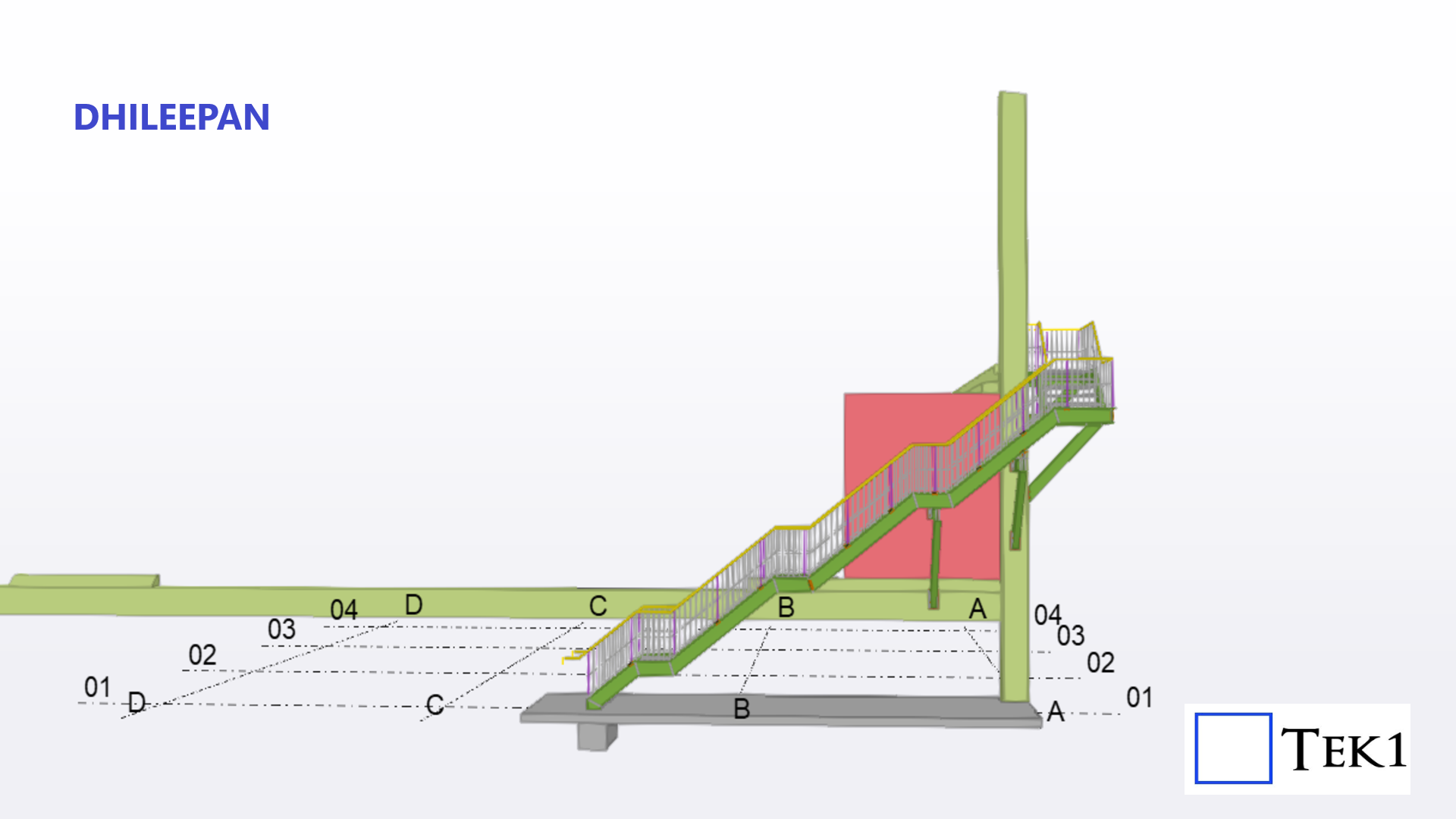
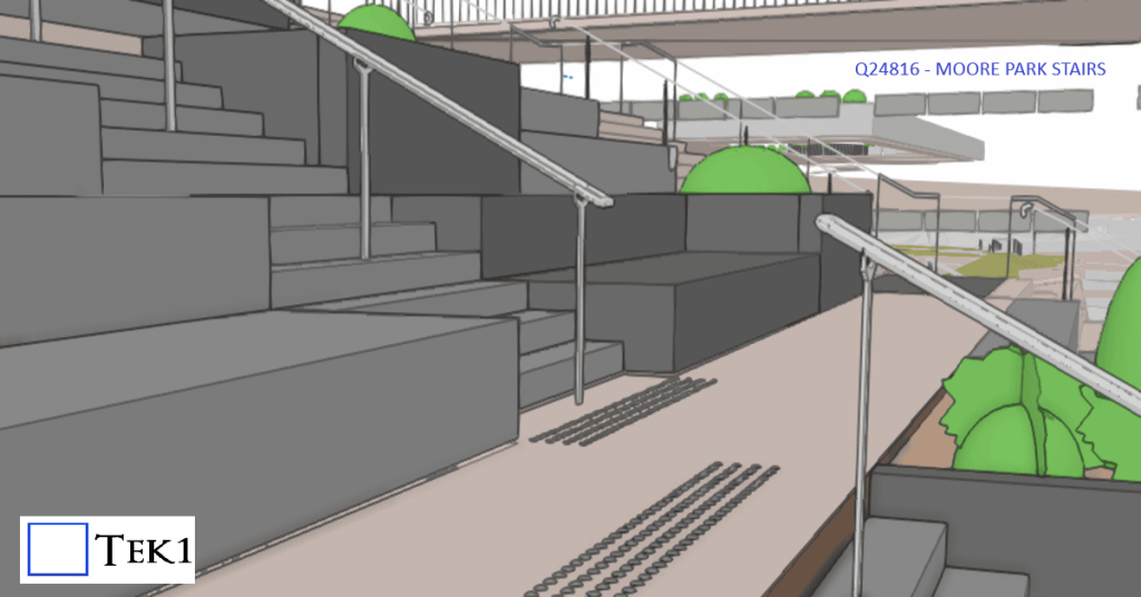
At Moore park, there are several stairs & ramps. Among them is a stair which connects walkways at different levels. The direction of the stairs is perpendicular to the direction of the walkways.
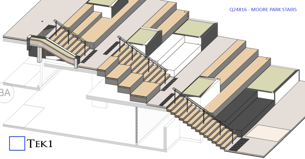
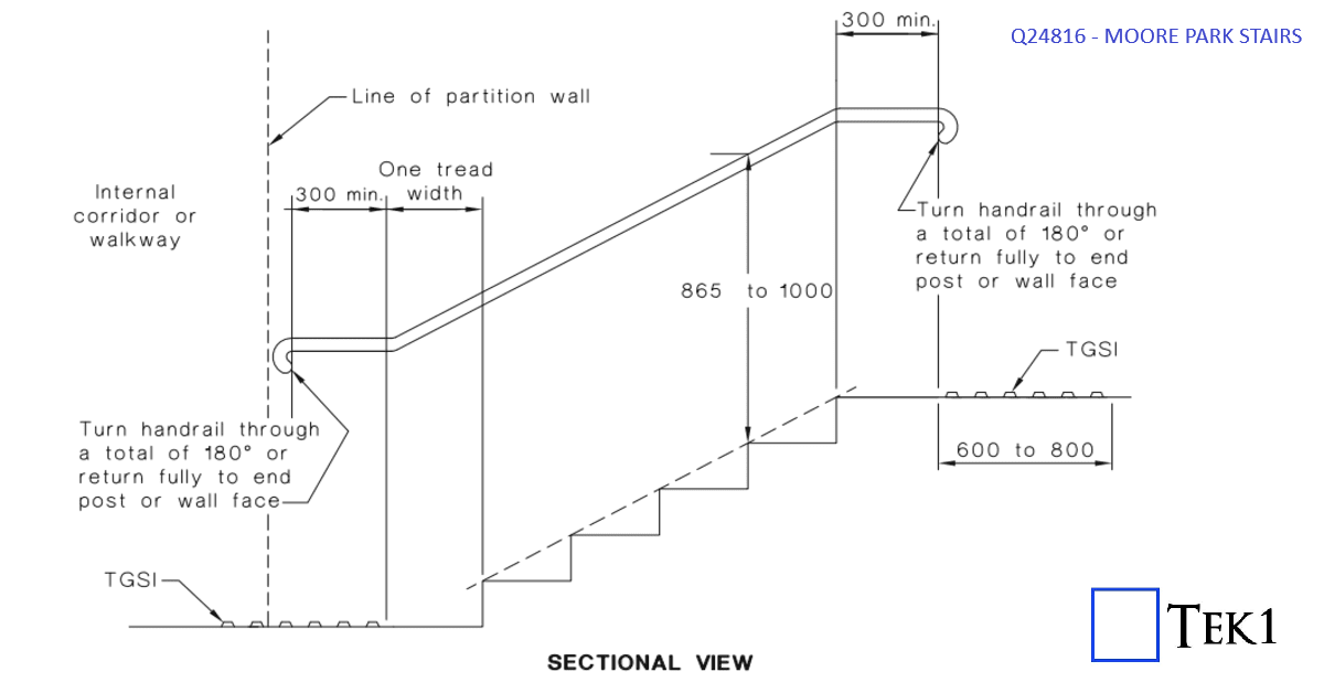
According to the sandards, handrails at stairs must extend beyond the stair flight to improve accessibility and safety. The standard requires:
- 300 mm extension beyond the landing nosing at the top, and
- The going of the first tread + 300 mm extension at the bottom.
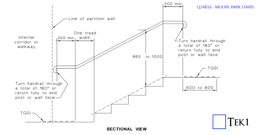
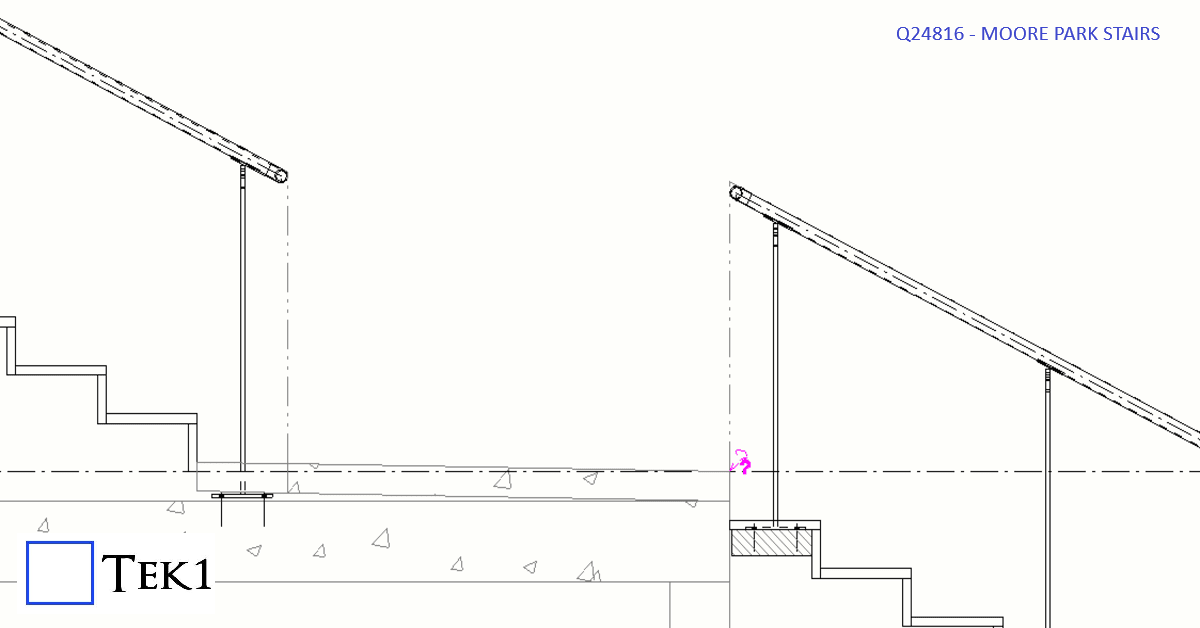
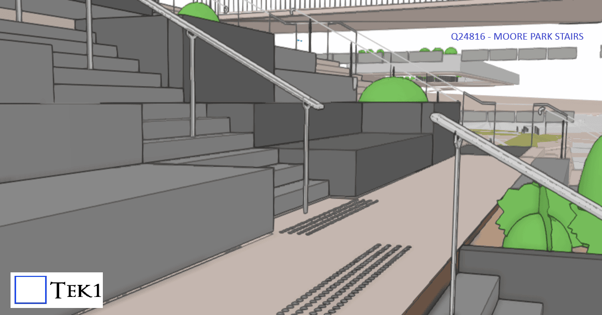
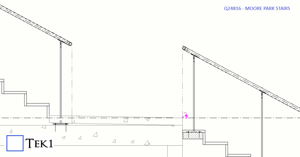
However, extending the handrail rail would protrude in the walkway & could cause collision hazard or reduce the effective width of the walkway.
To avoid this, the handrail extension was omitted. The architect has marked this as performance solution & this is one of the few cases where this 300mm extension does not apply.
-

Avoiding Errors In Updating Modified Drawings
When the model is amended after issuing the first set of drawings, the affected assembly drawings will appear as “Parts Modified” after numbering is completed. While updating such drawings, certain considerations are important to ensure effective and quick detailing.
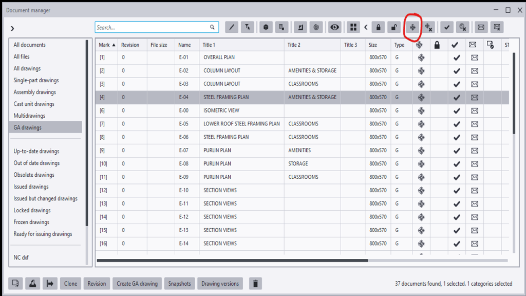
1. Freeze Option
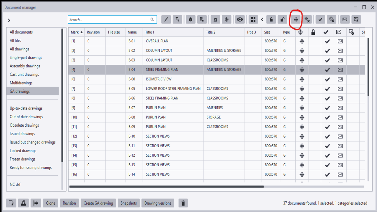
When Freeze is OFF, Tekla automatically updates dimensions according to the movement of parts. While this may seem convenient, the decision to turn Freeze ON or OFF depends on the nature of the amendment.
- If no new members are added to the assembly and only existing parts are moved, it is recommended to keep Freeze OFF, as Tekla will correctly update the dimensions.
- If new parts are added to the assembly and Freeze is turned OFF, Tekla will automatically generate additional dimensions for the new members and may also alter existing dimensions. This can result in extra work to restore the original dimensioning arrangement.
Guideline:
- When no new parts are added, turn Freeze OFF.
- When new parts are added, turn Freeze ON.
2. Snapshot Option
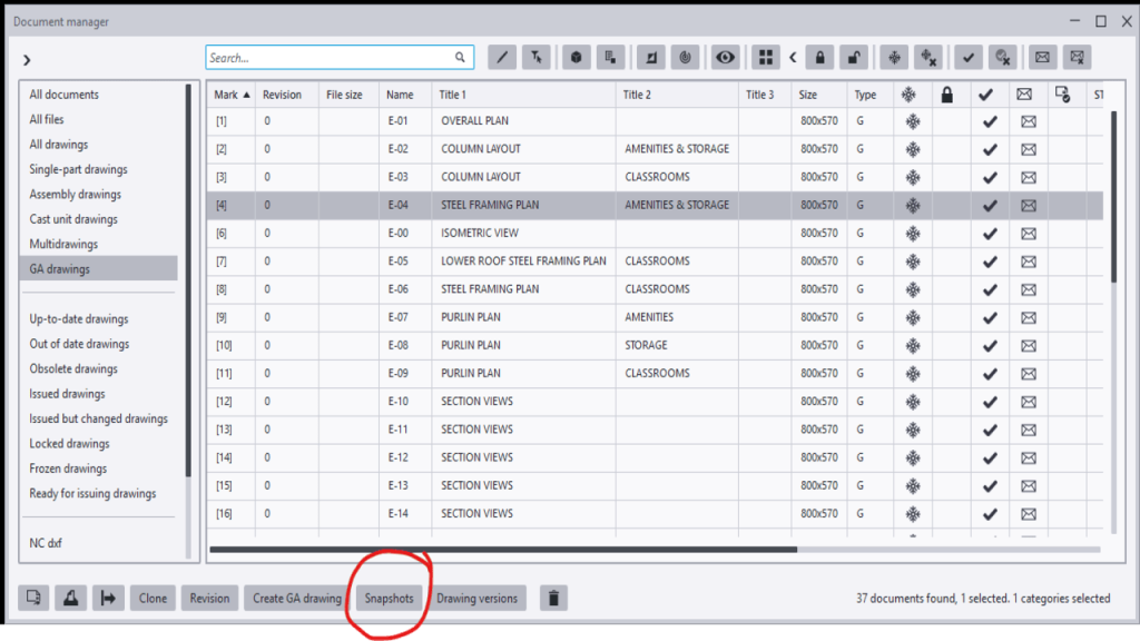
Among the drawings marked as “Parts Modified,” not all drawings necessarily contain actual changes. Some assembly drawings may appear as modified because they share common connection components with other assemblies that were amended.
In such cases, the drawing may not have any visible changes and may only require an open-and-close action. However, there is a risk that certain dimensions may be automatically deleted or altered by Tekla during the update.
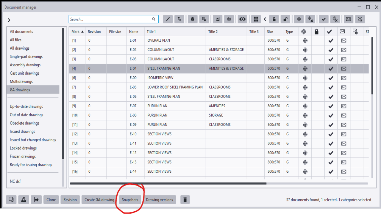
To avoid missing dimensions or unintended changes, the Snapshot option is highly useful. It allows detailers to compare the drawing before and after the update. By reviewing the differences, any unnecessary or unintended modifications can be identified and corrected, thereby minimizing the risk of errors.
-
Muswellbrook Tafe
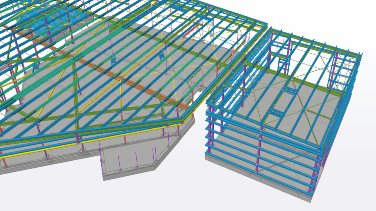
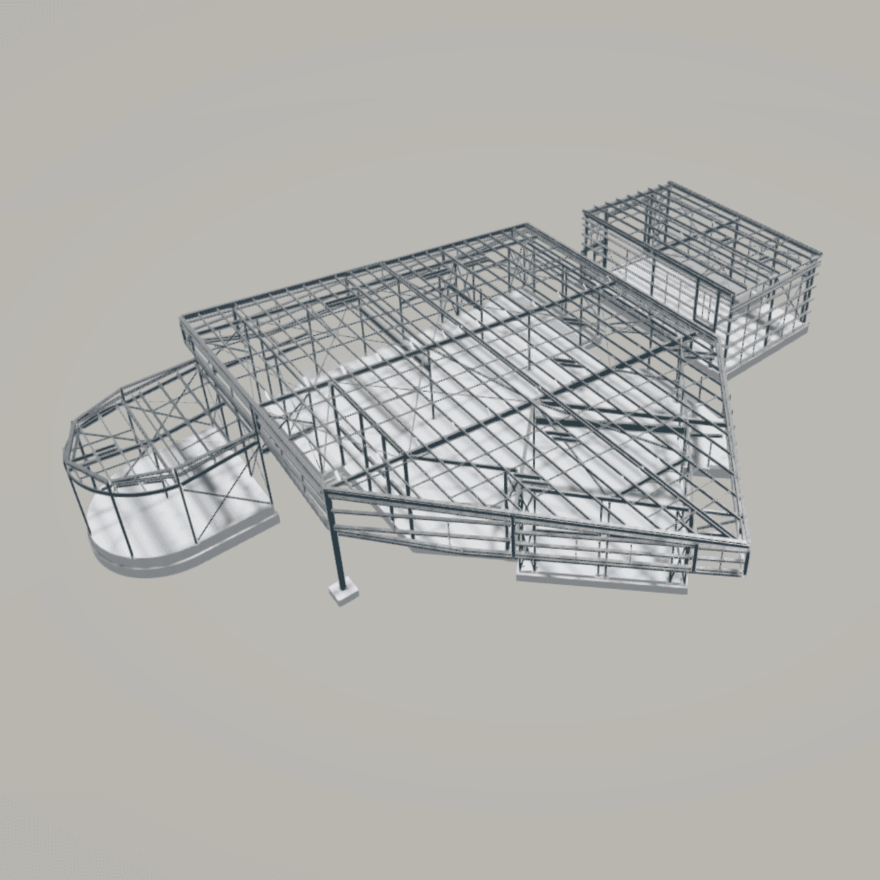
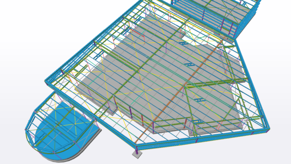
The Stage 3 Works at Muswellbrook TAFE, located on Maitland Street, NSW, represent a significant milestone in the campus’s ongoing development and modernization.
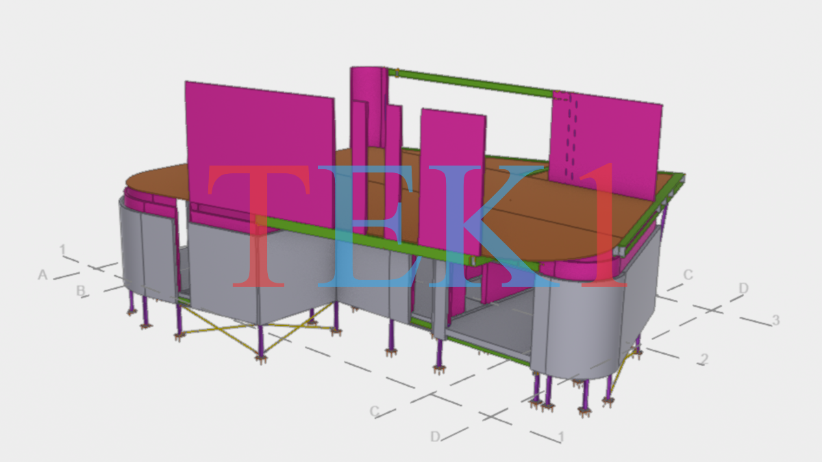
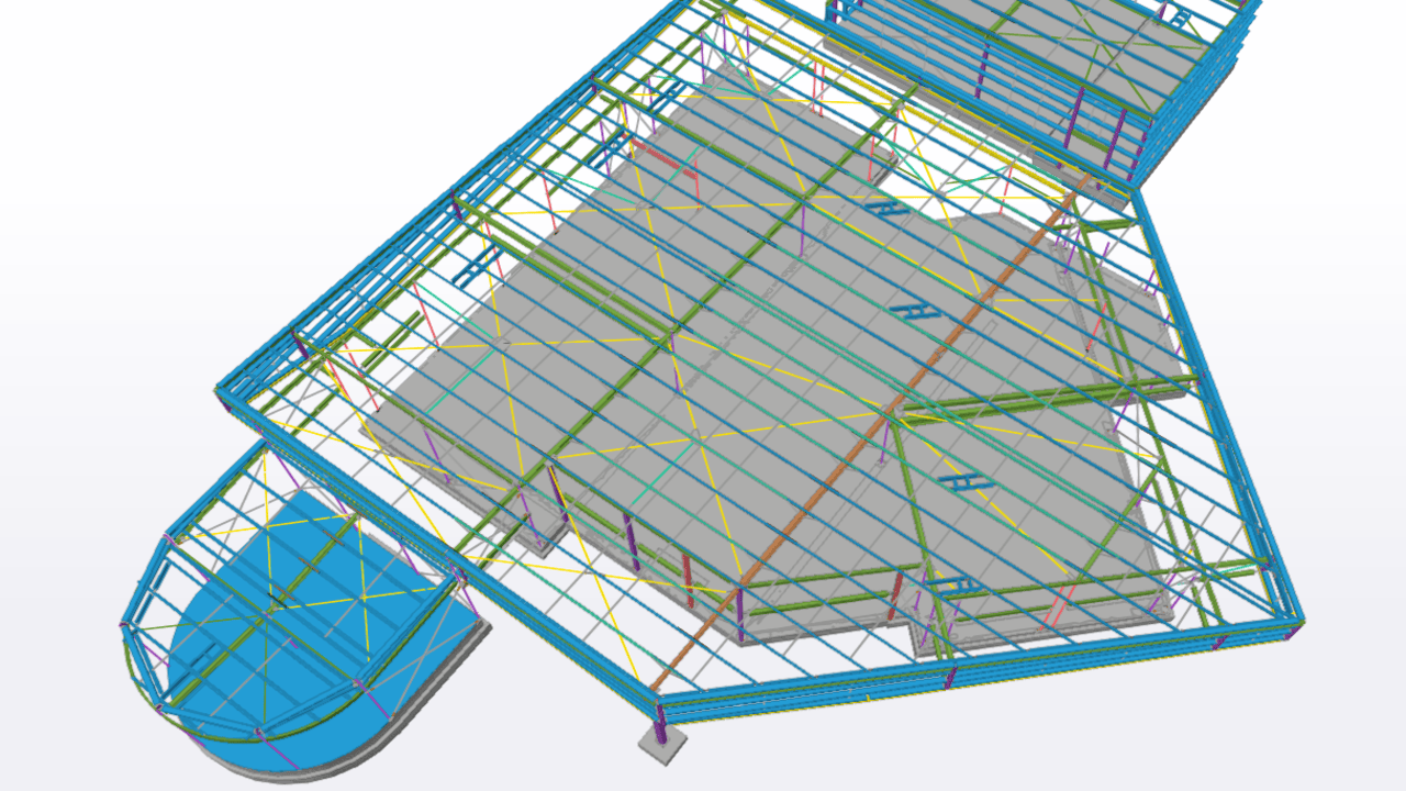
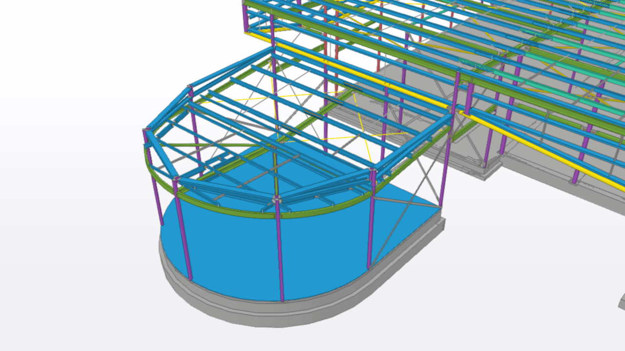
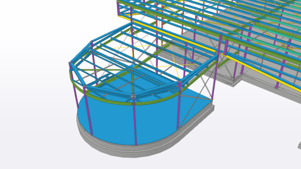
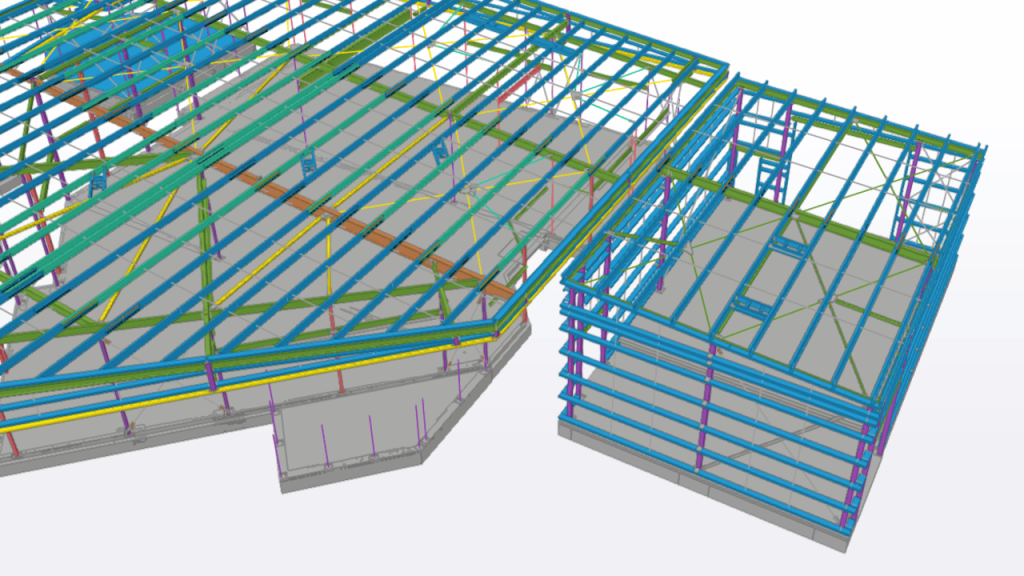
The new development comprises a storage warehouse, a curved amenities area, and multiple classrooms housed within a large integrated structure. The project involved a complex structural steel framework designed to support diverse functional spaces under one roof.
A key challenge during this stage was coordination with the mechanical services contractor, as several ducts and ventilation systems initially clashed with the structural steel members. Through collaborative design reviews, practical solutions were agreed upon—relocating steel members at certain locations and adjusting duct routes at others—to achieve optimal constructability without compromising structural integrity or service performance.
-
Hunter Street Ramps & Gates
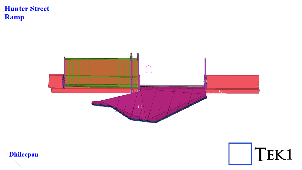
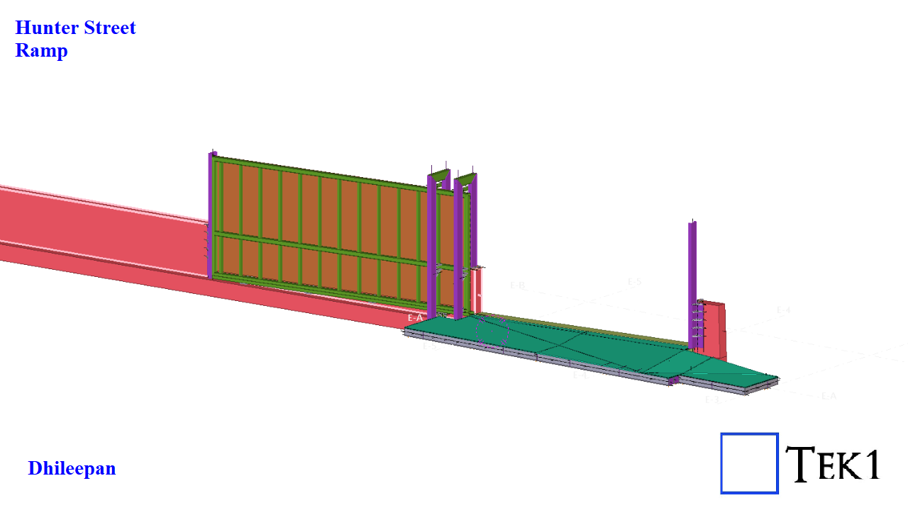
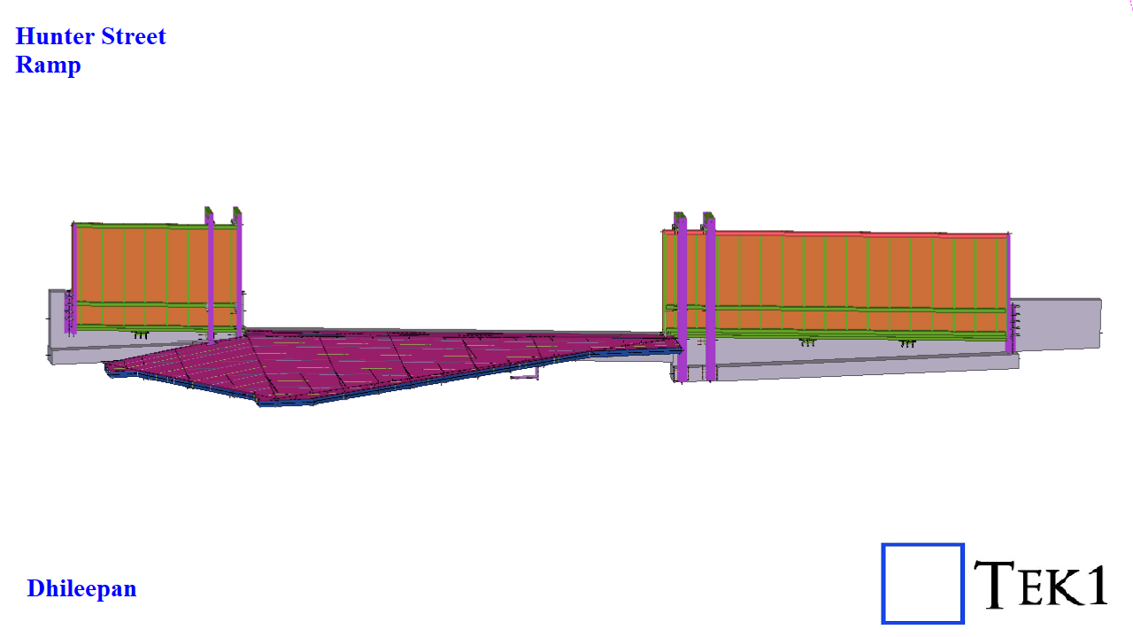
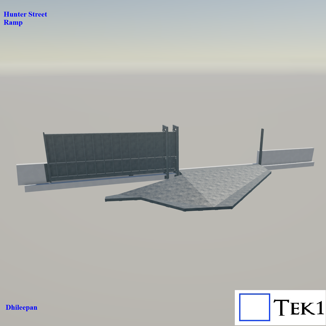
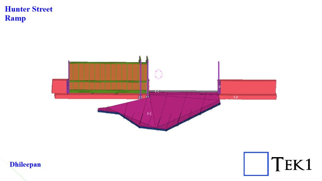
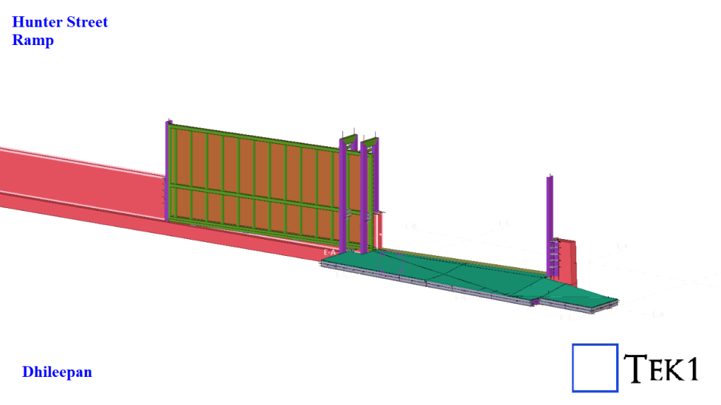
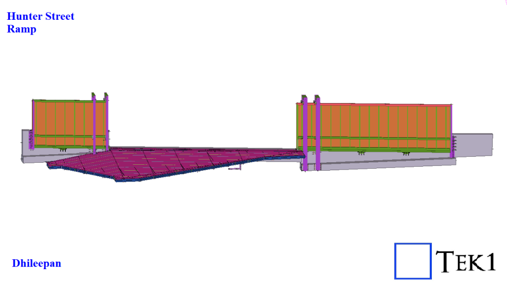
The Hunter Street Project involves a total of three unique ramp and gate assemblies, each designed with a distinctive geometry and function.
Unlike conventional ramps that slope in a single direction or follow a straight alignment, these ramps are far from ordinary. Each one features multiple slopes and apex lines, requiring precise modeling and coordination to achieve seamless transitions and accurate fitment on site.
The associated gate systems include both single-leaf and double-leaf sliding gates, each integrated carefully with the ramp slopes to ensure smooth operation and proper clearances.
Structurally, each ramp is composed of a series of 4 to 8 frames.
Every frame includes:- A chequer plate deck at the top for slip resistance and durability.
- A base plate at the bottom for connection and stability.
- Waffle-type stiffeners sandwiched between, providing rigidity while minimizing weight.
This setup requires engineering precision and modeling expertise. Tek1 had to provide inputs and suggestions to design the slopes in a way that ensures smooth operation of the sliding gates without imbalance.
-
Spotting the Hidden Error in an “Approved” Stair Project
Recently, we received a stair project that had already been detailed by another party and even approved by the design consultants. For reasons unknown, the project eventually came to Tek1.
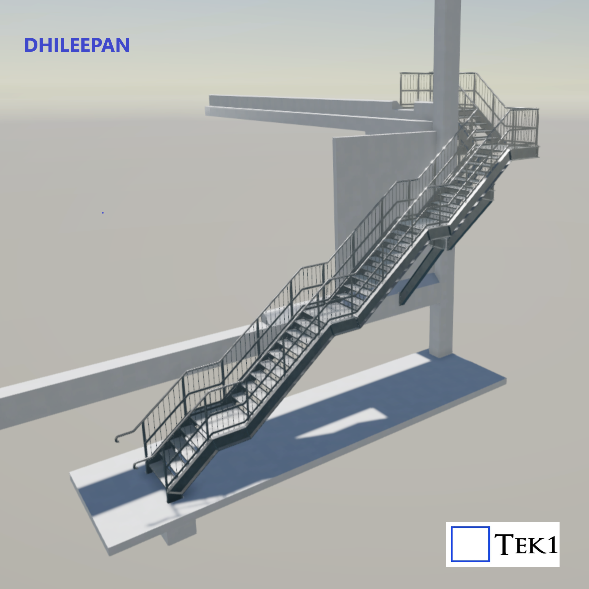
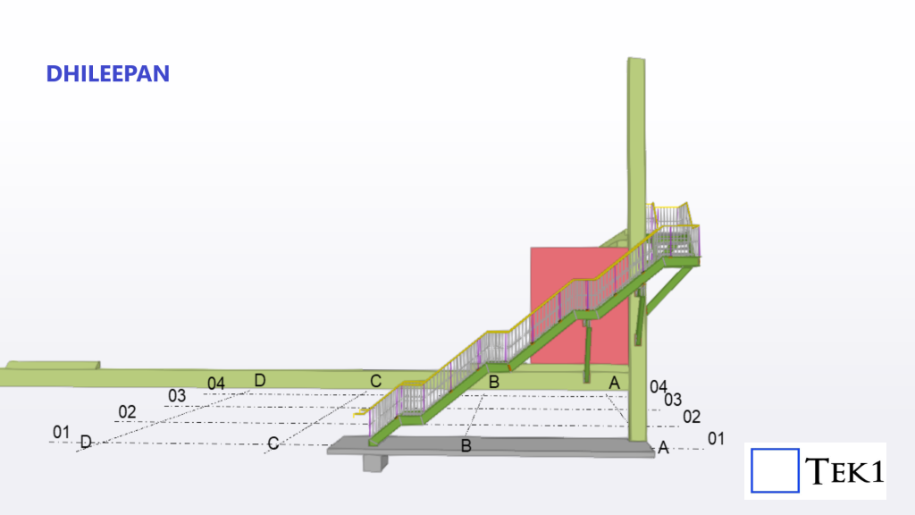
The scope involved a large five-flight stair with a 90° turn. We were provided with the GA drawings and assemblies prepared by the previous detailer, stamped with approvals, and instructed to simply follow the approved drawings for any RFIs raised.
At first glance, it would have been easy to assume everything was in order. But at Tek1, we believe that blindly following drawings — even “approved” ones — is risky. Every project deserves a careful check against standards.
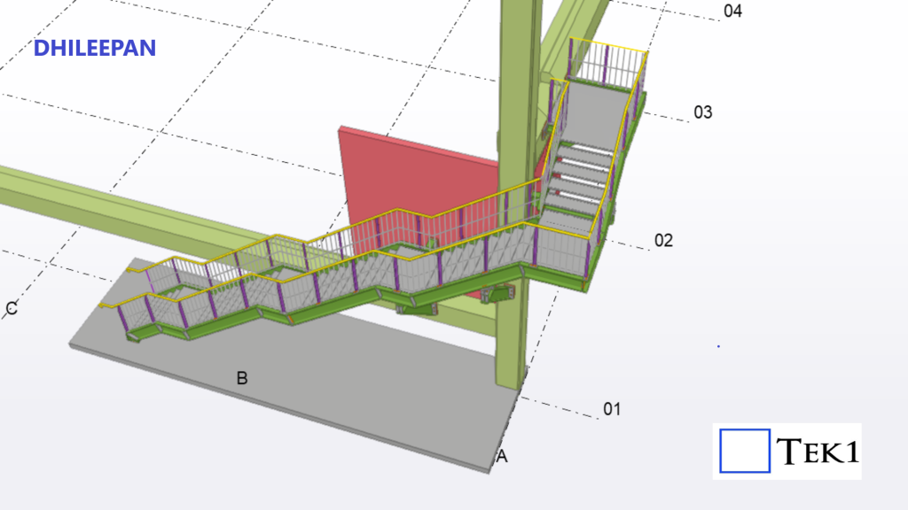
The Error That Changed Everything
During our review, we noticed a critical issue: while all risers were at 190 mm, one riser was set at just 149 mm. This not only broke the uniformity but also violated the applicable stair standards.
We immediately highlighted this to the client. What seemed like a “small” mismatch in a single tread had major implications. To correct it, the entire stair had to be revised:
- Riser height was adjusted to 188 mm.
- All mid-landing RLs shifted.
- Stringer slopes changed.
- Handrails and support frames were reworked.
In short, one overlooked error had a ripple effect on the entire structure.
Lessons Learned
Projects that land with us after being dropped by other detailers often arrive with extreme urgency, as valuable time has already been lost. But no matter how hectic the schedule, Tek1 follows one principle: check the input drawings against standards before proceeding.
This extra step not only avoids costly errors but also ensures safety and compliance — something no deadline should compromise.