Author: Dhileepan

  • Surry Hills Village – Stair

    Surry Hills Village – Stair

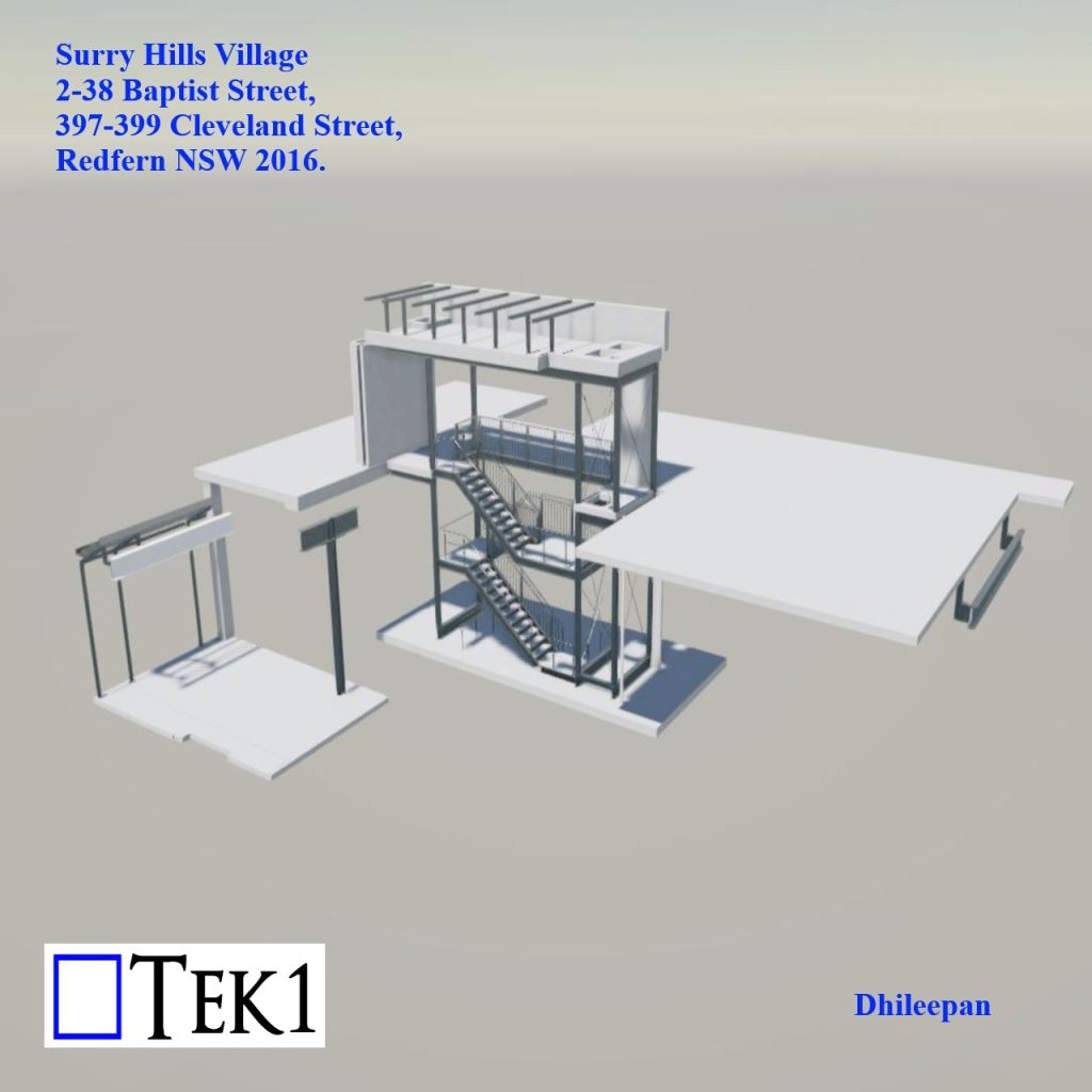
    Renovation projects often present unique challenges, especially when integrating new elements into existing structures. Surry Hills Village, located on Baptist Street, NSW, encountered such challenges during the addition of a stair to Building-H.

    At the project’s outset, only the existing structure stood. As Tek1 began detailing the stair, concrete columns, beams, and slabs were poured, necessitating adjustments to accommodate the evolving design. Discrepancies between the initial design width and site measurements required the stair’s width to be reduced.

    Further complications arose when the balustrade design underwent a complete overhaul after fabrication had begun. Tek1 meticulously detailed the balustrades to preserve part numbers and maximize the reuse of fabricated components.

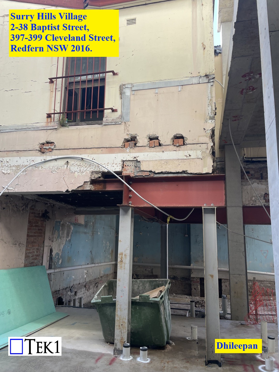
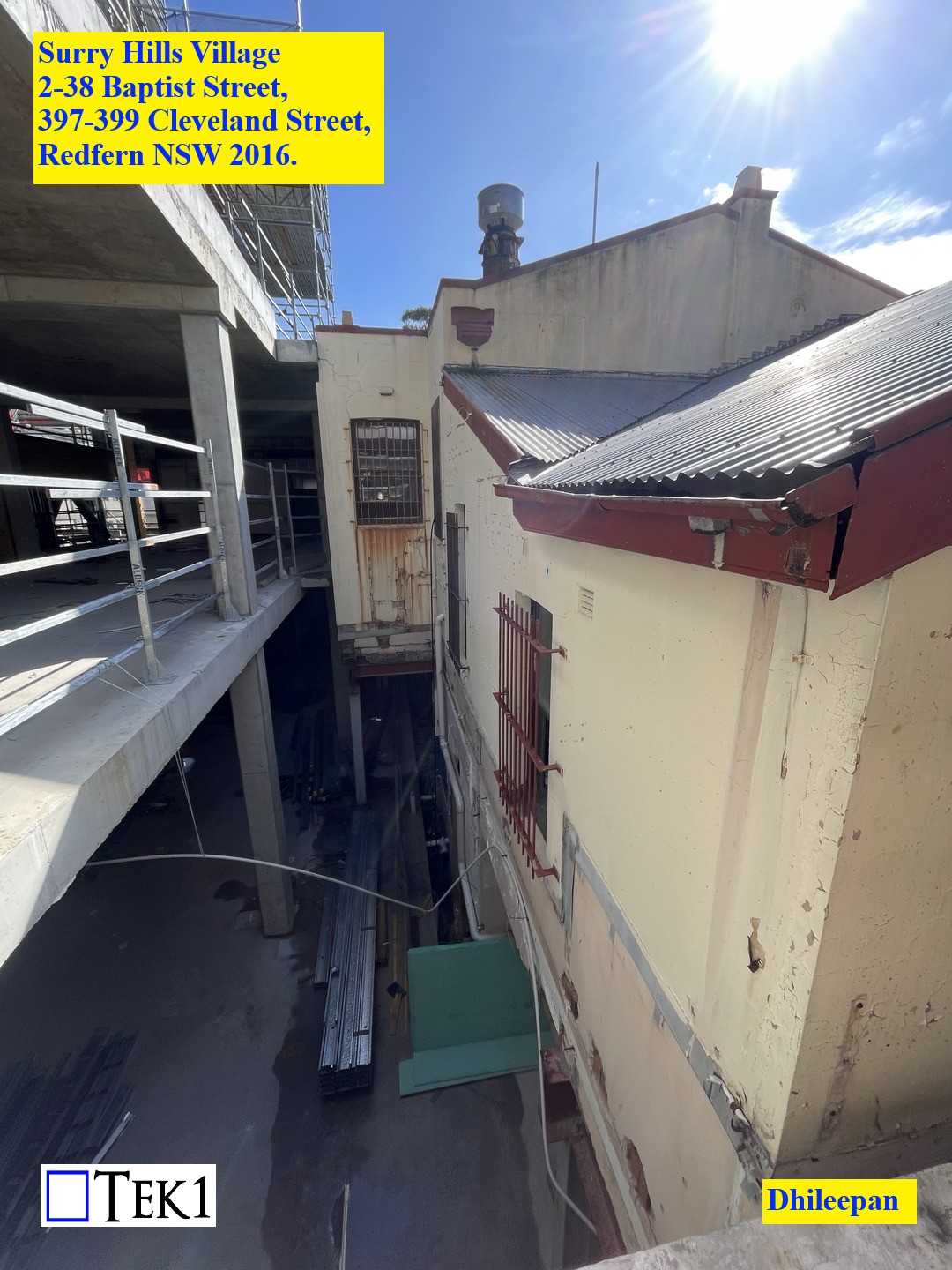
    Even after assemblies arrived on-site, adjustments were still necessary to align with site conditions. A total of 43 RFIs were generated throughout the project, supplemented by site images and measurements to inform decision-making.

    Based on site images, Tek1 proposed alterations to the existing structure, helped preemptively avoid changes that would have been disruptive on-site.

    Despite its seemingly straightforward nature, the stair project spanned 10 months from commencement to final delivery, underscoring the intricacies of renovation endeavors.

  • Residential Building

    Residential Building

    Nestled at 38 Rennie Street, Coburg stands a residential marvel, meticulously detailed by our dedicated team. This architectural gem boasts of being one of the largest, most advanced, and aesthetically pleasing buildings in the neighbourhood.

    Spanning across a sprawling area of 981 square meters, this residential masterpiece demanded a profound understanding of architectural intricacies. Seamless integration of structural steel and the architectural intricacies like glass panels, door hinges and aluminium composite panels was meticulously planned and executed.

    What sets this project apart is the deliberate choice to leave certain steel columns exposed, a rarity in residential constructions. Rather than concealing them, these columns stand proudly, adding an industrial charm to the structure. To complement this unique design choice, a diverse range of finishes were employed across the steel assemblies. In total, five distinct finishes were meticulously curated to enhance the visual appeal and architectural integrity of the building.

    Model Link: https://app32.connect.trimble.com/tc/api/2.0/s/AAfRyGm_8Ohs_CzeJlPCOFfrU4yiC3tAaTkZWGDnhEU4WPWI1wnhJrUB_-EWfnOo

  • Design Challenges: RFI and Amendment

    Design Challenges: RFI and Amendment

    Author: Pon Dhileepan

    This narrative unfolds the profound impact a meticulous steel modeller can have on structural design.

    In a residential villa, a canopy has been included at the entry. To support the canopy on the ground floor, as per the design, a 20Ø threaded rod was initially intended to extend from the floor beam to pick up the canopy frame.


    However, during the modelling process, two issues were identified.

    First, the rod would be visible through a glass window, impacting the building’s aesthetics.

    Second, a misalignment between the canopy frame and the floor beam made it impossible for the rod to properly support the canopy.


    To address these challenges, a Request for Information (RFI) was initiated. The goal was to find innovative solutions that would not only maintain the intended design but also overcome the unexpected hurdles.

    In a dynamic exchange of ideas, acknowledging the misalignment challenge, a new EA wa. This adjustment aimed to harmonize the canopy frame with the floor beam, ensuring a seamless integration of the threaded rod and the overall structural elements.


    Additionally, the window was split into two sections, covering the rod with a silicon butt joint to maintain the building’s visual appeal.


    In the face of unexpected design challenges, the collaborative process of raising an RFI and responding with creative solutions led to a harmonious blend of form and function.

  • Hurstville Golf Club

    Hurstville Golf Club

    The Hurstville Golf Club, located at 57 Lorraine Street in Mortdale, comprises three buildings: a Cart Store, Proshop, and Club House. The Cart Store and Proshop are single-story structures, while the Club House is a two-story building.

    Design details at the junctions of these three buildings were incomplete, and TEK1 proposed member locations and connection details. These proposals were reviewed and accepted by the consultants.

    Completed Building


    Tekla Model


    Tekla Steel Model

  • Watches of Switzerland – Renovation

    Watches of Switzerland – Renovation

    Author: Pon Dhileepan

    The Watches of Switzerland shop in Collin Street, Melbourne, has undergone a remarkable renovation, blending modern sophistication with heritage charm. A lift, 2 storey stair and frames for wall have been newly added.

    The lift runs from the ground floor to the second. Initially, the lift columns were designed for 10.8m. Since, this is an indoor construction, we raised query  about maneuvering the 10.8m columns inside & rotate them to their positions. Redesign happened & the columns were split to 4.5m max.

    The key responsibilities in this project are:

    • Coordination with the lift drawings
    • Marking and requesting essential site measurements through detailed sketches
    • The lift columns are bolted to the soffit of the roof slab. It s the responsibility of the modeller to alter the builder & ensure that there are no existing concrete beams at the vicinity of the lift columns.
    • Proposing structural member & their connections at areas that were missed out in the structural drawings.

    Refer to the attached model snaps below:

    Overall Renovation

    Lift

    Stair

    Wall Frame

  • Asymmetric Zed Purlin

    Asymmetric Zed Purlin

    Author: Pon Dhileepan

    Lysaght Zed sections feature one broad & one narrow flange, sized so that two sections of the same size fit together snugly, making them suitable for lapping.
    The table below from the lysaght catalogue clearly shows the difference in sizes of each flanges.

    Lysaght Zed Purlin Catalogue

    The purlin bolts are always placed equidistant from the centre & hence the steel modeller does not have to worry about whether the broad flange of a purlin comes at top or the narrow flange. The broad & narrow flanges will be placed alternatively at the site. This is the case for almost all the times.

    But very rarely, there might be additional bolts/holes at the top flange or bottom flange and the steel modeller has to consider modelling the purlins with their exact orientation i.e, whether broad flange of a purlins comes at top or the narrow flange.

    For instance, the below design demands for M12 bolts or hook rods from the top flange of the Zed purlin to support the nearby gutter. Hence the modelling has to be precise about the broad flange & narrow flange for each purlin in a continuous row.

    Example Design
  • Life Saving Facility – Smiths Beach

    Life Saving Facility – Smiths Beach

    Author: Pon Dhileepan

    This was my first project as a modeler, completed in January 2018.

    A circular structure steel structure surrounded by timber battens was modelled & detailed for Smiths Beach, Yallingup WA. Completed site image is attached at the bottom

    The structure consists of a bottom ring, a body made as circular cage & a top ring at 5° slope. The body cage is covered by curved SHS flames that has cleats to pick up the outer battens. The entire structure rests of 4 CHS columns.

    BOTTOM RING
    BODY CAGE
    COVER FRAMES
    TOP RING

    There are 3 operable windows & a door, all made of steel frames. Since the structure is elevated from the ground, a staircase of arithmetically increasing width is also detailed to access the life saving facility.

    STEEL STRUCTURE
    FINISHED TEKLA MODEL
    FINISHED SITE IMAGE
  • Getting the Drawings Reviewed

    Getting the Drawings Reviewed

    Drawings are always submitted for approval before fabrication. When any changes are given by the structural engineer or the architect, after implementing the changes, the drawings must be submitted again for 2nd approval so that the structural engineer & the architect will review & approve the drawings.


    In some cases, the architect & the structural engineer skip their duty of reviewing & question the detailer whether the detailer has implemented all the changes. Refer below image for an example.


    In such cases answering with a “yes” might cause trouble to the detailer & the corresponding concern in he future.


    Rather than answering the question, the detailer can pose a question to the question asked like “Have the Structural Engineer and Architect approved?”.
    By such way, the detailer has attended to the structural engineer or the architect and also the duty to review the drawings has also been assigned once again to him.

  • Traffic Railings

    Traffic Railings

    Author: Pon Dhileepan

    A new bridge on the Crescent right turn grade sepration over the Crescent and city west link at Lilyfield and Annandale at 4.6km west of Sydney Rozelle interchange and wester harbour tunnel is built for the NSW Government.

    This bridge is more than 400m in length with approach & departure ramps. RHS (Rectangular Hollow Section) steel railings are provided on both sides of the bridge.

    The barriers curve along the bridge and also the levels rise and fall as the bridge goes on. Two consecutive railings are connected together by a hollow connector. Refer to the images below.

    ISOMETRIC VIEW
    PLAN VIEW
    RAIL ASSEMBLY
    RAIL CONNECTORS