These are steps. When you get to the top, you’ll be an AutoCAD master programmer.
I’ve compiled a list. There’s actually quite a bit involved. I don’t think you can get away with simply not knowing anything about unamanged ObjectARX world. Here is the list below – which I will update. If you see any notable topics which I have missed, please feel free to add a note and I will update the list.
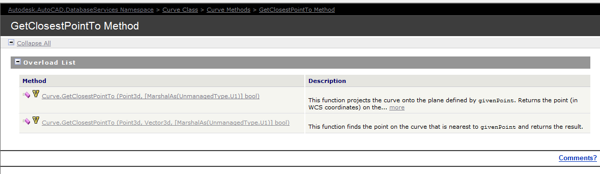
Documentation of the GetClosestPointTo method of the curve object – the overloads are extremely limited. So we have to be somewhat creative in obtaining a solution.
The Genesis of this problem
This is a tricky little problem and I could not find a solution on the forums. So I resolved, upon discovering the solution, to oblige posterity and the public, to publish my findings.
Specific Notes about this problem
Now the following code has been generalised to the specific case of Lines and a non-descript curve (which of course is an abstract base class), but the general principles can be applied to any type of curve.
Notes on implementation
Unfortunately, the curve object exposes a method: GetClosestPointTo, which is only overloaded to accept points and not other curves. In order to deal with this rigmarole we’ll have to first, convert the curve to a `Curve3d` object which is a member of the Autodesk.AutoCAD.Geometry namespace as distinct from the Autodesk.AutoCAD.DatabaseServices namespace.
We have someone who is pointing to the monitor. Makes perfect sense right?
This is largely a replication of what is contained in the documentation without the extraneous (and extremely confusing) intertwining of WPF/WinForms functionality. Personally I believe when engaging in hello world functions that they should be as simple as possible.
I have done as much here.
In time, I will add further details to provide you with some more information on the classes that are used. The main thing to pay attention to here is the FullSubentityPath class as well as the PointMonitorEventArgs.AppendToolTipText(string) method. More details will follow later on. For the moment, parse this code and try to understand what you can:
A physical representation of a Result Buffer outside the world of ObjectARX. hahha.
Unfortunately, and unsurprisingly, the documentation is a little sparse on this point. But somewhere deep within the annals of the AutoCAD documentation I found this little beauty:
Here is the documentation. But for you folks who may find that the link does not work, I will also copy and paste verbatim, what is said there:
The ResultBuffer type is a class that mirrors the resbuf struct defined in the ObjectARX SDK. The resbuf struct provides a flexible container for AutoCAD-specific data.
An Autodesk.AutoCAD.DatabaseServices.ResultBuffer class object is used in much the same way as a resbuf chain. You define a ResultBuffer and populate it with a sequence of data pairs. Each pair contains a data type description and a value. In the managed API, these data pairs are instances of theAutodesk.AutoCAD.DatabaseServices.TypedValue class. This utility class serves the same purpose as the restype and resval members of the resbuf struct.
The TypedValue.TypeCode property is a 16-bit integer value that indicates the TypedValue.Value property’s data type. Acceptable TypeCode values depend on the specific use of aResultBuffer instance. For example, TypeCode values that are suitable for an xrecord definition are not necessarily appropriate for xdata. TheAutodesk.AutoCAD.DatabaseServices.DxfCode enum defines codes that accurately describe the full range of possible ResultBuffer data types.
The TypedValue.Value property maps to an instance of System.Object, and theoretically may contain any type of data. However, the Value data must conform to the type indicated by TypeCode to guarantee usable results.
You can prepopulate a ResultBuffer by passing an array of TypedValue objects to its constructor, or you can construct an empty ResultBuffer and later call theResultBuffer::Add() method to append new TypedValue objects. The following example shows a typical ResultBuffer constructor usage:
using (Xrecord rec = new Xrecord())
{
rec.Data = new ResultBuffer(
new TypedValue(Convert.ToInt32(DxfCode.Text), “This is a test”),
new TypedValue(Convert.ToInt32(DxfCode.Int8), 0),
new TypedValue(Convert.ToInt32(DxfCode.Int16), 1),
new TypedValue(Convert.ToInt32(DxfCode.Int32), 2),
new TypedValue(Convert.ToInt32(DxfCode.HardPointerId), db.BlockTableId),
new TypedValue(Convert.ToInt32(DxfCode.BinaryChunk), new byte[] {0, 1, 2, 3, 4}),
new TypedValue(Convert.ToInt32(DxfCode.ArbitraryHandle), db.BlockTableId.Handle),
new TypedValue(Convert.ToInt32(DxfCode.UcsOrg),
new Point3d(0, 0, 0)));
}
What does all this mean?
I can’t justify an entire post without adding some degree of value: let’s try simplify its meaning a little more. Basically, result buffers are like CLR dictionaries: they are made up of a series of TypedValue objects. These TypedValue objects are like Key-Value pairs which you can fill with different types of data (i.e. AutoCAD data), or even non-AutoCAD data. The values you can use for the Key (in a TypedValue object) are basically that which are specified as DxfCode values.
Result Buffers are:
Made of TypedValue objects.
Typed value objects are like Key Value pairs
Where the key of the TypedValue is a DxfCode and
The value of the TypedValue is any AutoCAD type which corresponds to the DxfCode set as the key.
I hope that’s making some degree of sense? It will be a sad day if such an explanation obfuscates what is written in the documentation (where it exists) to a greater degree than the documentation itself. Anyways, I do hope it helps.
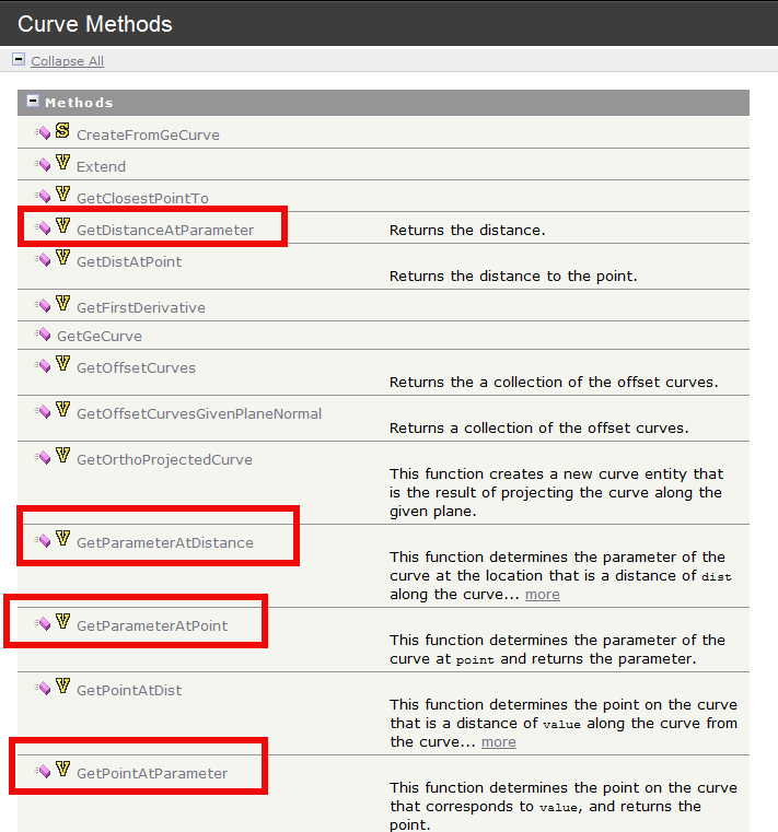
A perusal of the .net Reference Guide reveals these types of functions:
This is a snapshot of the .net API Reference guide.
But as per usual, there is no explanation in the documentation as to what a exactly a parameter is. This is best explained by example. Stay with me here:
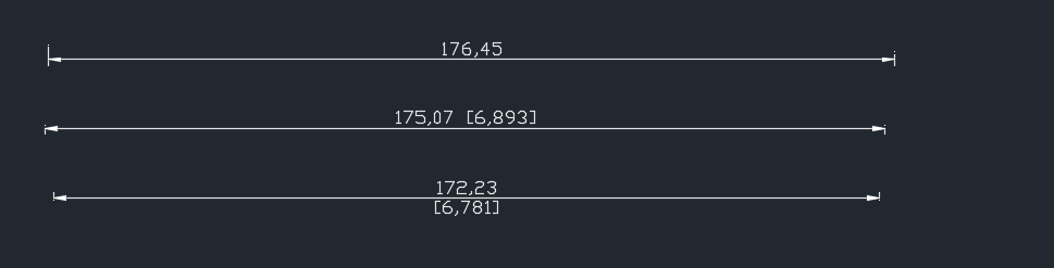
Suppose you have a curve (i.e. a polyline) that has n points. Or in this case, 10 points.
If you called `polyline.GetStartParam()` you’d get a value of 0. And if you called: `polyline.GetEndParam()` you’d get a value of 9. You’ve got 10 points of course, but remember, you’d get a value of 9 because it’s all zero index based.
Some Notable Exceptions:
Now you have to remember that Ellipses and Circles are also curves too. If you asked an arc or a circle a question about its parameter, then you are really asking it about the angle around the circle or arc (starting from 0). E.g. circle.GetPointAtParameter(0) should give you (100,0,0) and circle. GetPointAtParameter (2π) should give you (100,0,0).
Suppose you want to calculate the halfway distance between vertex 0 and vertex 1 for a polyline? Should you use polyline.GetPointAtParam(0.5)? The answer is: no! This is because the mapping between parameters and points need not be linear. To be safe you should use: getDistAtParam() to get the distances d0 and d1 and you should then use getPointAtDist( (d0 + d1) / 2 ).
The boffins at AutoDesk have ported that which has existed in the ObjectARX API into .net – it’s basically a wrapper. And on a side-note – it is well worth reading the ObjectARX documentation for that very reason – let’s face it – the documentation for AutoCAD APIs are not very good. So definitely read the ObjectARX API.
Here are some very useful resources that you will need in order to fully utilise this API:
Think of Breps as a novel way of representing shapes in a hierarchical way. This won’t make much sense to you – but consider the example below: re: traversal of this hierarchy.
What is it useful for?
Brep API is useful for: (i) traversing a hierarchy of shapes, (ii) Point Containment calculations and (iii) Meshing.
(A) Traversing a hierarchy of shapes.
Ok. When you think of a cube for example, you have a 3d object:
Cube (the cube can also be thought of as a shell – a set of connected faces).That cube is made up of 6 faces, all of which are squares.
Those faces are made up of 4 edges each.
Those edges are bade up of 2 vertexes bounded by a curve.
All 3d objects can be broken down somewhat into a hierarchy of simpler objects. The BREP API allows you to traverse that hierarchy and make queries according to your particular requirements/needs/application.
(B) Containment calculations
Let’s suppose you have a sphere and you want to determine whether a point lies within the sphere or outside of it. You could use the Brep API to make this determination.
(C) Drawing meshes to represent surfaces
You could use the API to create meshes which can approximate a 3d surface or object.
How are you going to identify one duplicate in a sea where everything looks the same?
Duplicates are a problem – an expensive problem, especially if you are dealing with hundreds and perhaps even over a thousand panels. Somebody cocks up – usually on the client side – but how are you meant to identify it?
You could manually do it, but then that will more than likely take a long time. Or you could just employ Tek1 to do that sort of thing for you. Here is a video demonstration:
It can work for all clients with only very minor modifications. Very well abstracted out in the code.
It is super fast. Comparing the thousands of elements in each drawing takes a bit of computing power – but with smart algorithms, you can cut down the time.
It can work in the marking plan and elevation or layout. The same code, the same command, but x3 the power.