Category: Precast Blogs

Tek1 has detailed over 100,000 precast panels over 19 years.
over 90,000 were detailed under a proxy name Advanced Pretty Pictures Pty Ltd

PRECAST PANEL DETIAILING
EXPERT PRECAST PANEL DETIAILING
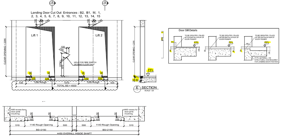
  • CONSIDERATRIONS-LIFT SHOP DRAWINGS FOR PRECAST

    The important things to be considered in lift shop drawings for precast is listed below:

    1. Core Setout.
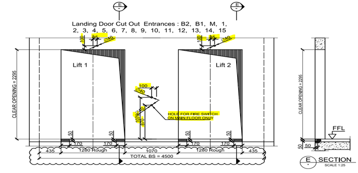
    2. Door Opening.
    3. Recess at the bottom of lift door.
    4. Landing Call Buttons penetrations.
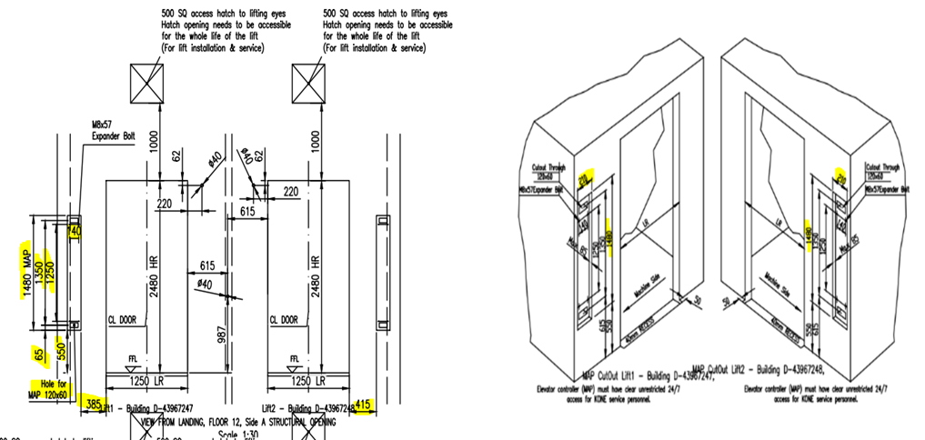
    5. Controller Box Penetrations.
    6. Service Penetrations and internal platform box.
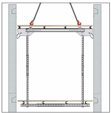
    7. Lifting Eye Placements & capacity.

         1. CORE SETOUT:

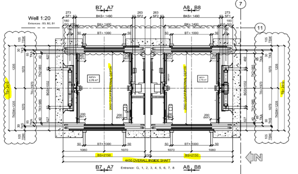
    1. Lift Core Panels Setout in Concrete plan and structural plan should match with lift core details.
    2. If any thickness of panels change keep inside dimensions unchanged, because inside dimensions are dictated by lift manufacturer’s drawings. Panels thickness change must affect only the outside dimensions of lift core.
    3. Propping method – Lift Cores are generally erected first. Higher level slab may not have been poured when lift core goes up. Hence propping of lift core need to have some special attention.

    2. DOOR OPENING:

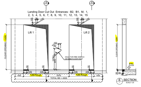
    1. The door opening width and height of lift in lift drawing should match with architect and structural drawings.
    2. Make sure that the height of lift door opening in lift drawing are measured from FFL or SSL.
    3. Minimum Header height should maintained Discuss with interested parities if there any doubt.
    4. Always consider the RL’s difference between FFL and SSL while  the opening height are finalized. FFL and SSL are usually different

    3. RECESS AT THE BOTTOM OF LIFT DOOR:

    1. The recess at the bottom of lift door (as per door sill detail) is provided for door frame installation. Make sure we take this into consideration
    2. The door sill details are not same for all projects we need to confirm the depth and width of recess at the bottom of lift door before start the detailing.
    3. If the door sill height recess is wrongly provided (i.e. Measured from SSL instead of FFL) then there will be a problem in installation of lift door frame.
    4. The provided recess depth should start from the end of clear opening of lift door.
    5. Make sure that the Door sill details provided in lift drawings are measured from FFL or SSL.

    4. LANDING CALL BUTTONS PENETRATIONS:

    1. Penetrations for landing call buttons, fire switch and other electrical purpose are to be placed as per lift manufacturer’s drawings.
    2. First confirm the view direction of lift drawing (viewed from landing i.e. Outside) and precast Setout. It will clear the location of the lift call buttons and other penetrations.
    3. Ensure the height of penetrations provided in lift drawings are measured from FFL or SSL.
    4. There will be penetrations of different diameter according to its purpose i.e. call buttons, electrical, fire switch etc. so concentrate more on size and location of penetration while detailing.
    5. Penetration locations and size may vary according to the respective floor entrances so refer the details from correct floor entrance which is given in lift drawings.  

    5.CONTROLLER BOX PENETRATIONS:

    1. Controller box may need a recess or in some cases could be a penetration.
    2. Ensure the location of the control box from the panel edge, we need to maintain the sufficient gap from the edge of the panel.
    3. Ensure the sufficient cover from reinforcement with the penetrations

    6. SERVICE PENETRATIONS AND INTERNAL PLATFORM BOX:

    1. Ensure the Hatch opening / exhaust opening need to be accessible for the whole lift for installation & service.
    2. In some case there will be an internal recess requirement to allow for attaching temporary platforms inside the lift for servicing the lift. Make sure these recesses are same RL and opposite.

        7. LIFTING EYE PLACEMENTS & CAPACITY.:

                 For the whole lift is closed by 2 types of lids One by cast-insitu lid and another by precast lid. If we have the precast lid, we need to consider the following things

    1. Connection between the vertical precast & lid
    2. Slope for the water drain
    3. Finish of the face of the lid
    4. Lifting Eye & Hooks for the Lift car & accessories fixing
    5. Ensure the Capacity & size of the Hooks from the lift design.

  • How to Quote For Jobs

    The Golden Rule: Be very clear and specific about what you are quoting for. e.g. I am only going to work on the following (insert specific details), and everything else is excluded.

    Why is this important?

    • Clarity: Your client will know exactly what you are quoting for. Use diagrams, and present documentation to improve clarity. The last thing you want is your client to call you and say: “what about the stairs?”. It will not do for you to turn around and say: “oops, I meant I was only quoting for structural steel”. Clarity eliminates these types of problems.
    • Limited Liability: Do not write a blank cheque for clients. If you return a quote to: “build a house” then this quote is essentially open ended. They might get the wrong ideas in your their head: how large is the house? How much material? How long will it take? How will it be built? What if the client keeps changing the design? How much time are you willing to devote to keep making those changes? Even worse, what if you are forced to keep redesigning a house according to the caprice of a third party – whom you have no control? i.e if an engineer and architect keep changing their designs, then you may be destroying your margins and taking a steep loss, as well as massively increasing the risks something goes wrong. Always limit your costs, in some way. Make this clear to clients.

    Variations:

    • Watch out for design and build jobs: As alluded to above, the design process is fraught with difficulties. Too much back and forth with engineers. Limit this liability in some way: e.g. perhaps by hours worked on a project.
    • How we quote: we quote to a specific set of drawings. Invariable, these drawings change due to the discovery of problems as the building/structure progresses. Whenever something changes: that adds considerable risk to the project, cost, and delays. These costs need to be recorded and passed up the chain. No longer can engineers, architects and builders make changes, willy-nilly, and pass on risk, expenses to sub-contractors with equanimity.

    Specific Examples of Quoting:

    1. Limit scope to a drawing number.
    2. Limit scope to a particular drawing revision.
    3. Limit scope to the number of beams etc.
    4. Limit scope to grid lines.
    5. Limit scope to quantities.
    6. Limit scope by listing exactly what you are building.
    7. And exclude everything else.
    8. Show diagrams so that your quotes are crystal clear. This gives confidence to the quotee – they will know that your quote is well considered, and probably accurate.

    Here are some examples, of how we quote.

    Northern Retaining Wall

    Detailing structural beams, connections details, according to the following scope:

    Drawing 1: Type – T1 250UC90 HDG QTY: 299

    Drawing 2: Type – T2-L 250PFC HDG QTY: 1

    Drawing 4: Type – T2-R 250PFC HDG QTY: 1

    Drawing 5: Type – T7 250PFC HDG QTY: 26

    Drawing 6: Type – T8 250PFC HDG QTY: 1

    EPH – Station Platform Northern Retaining Wall

    Drawing 7: UC 150 x 37.2 post with base plate. QTY: 58

    Drawing 8: PFC 200 with Base Plate. QTY: 4

    Everything else is explicitly excluded. Changes might incur charges via variations. Fully documentation will be provided.


    Highlight Items on a Drawing

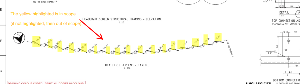
    • highlight scoped items in a drawing.
    • Add a note showing what is in scope. Why? Sometimes it is not immediately apparent what is being scoped in and out – especially if we are using a drawing with someone else’s markup. Do not simply highlight – we need the note as well. The note should say:
      • “The highlighted elements are in scope. If it is not highlighted, then it is OUT of scope”.

    Here is an example:


    Highlight Scopes + include a note
    Highlight Scopes + include a note


  • HOB AND ITS TYPES

    HOB
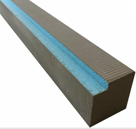
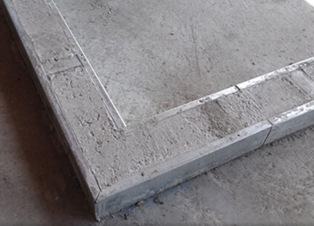
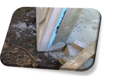
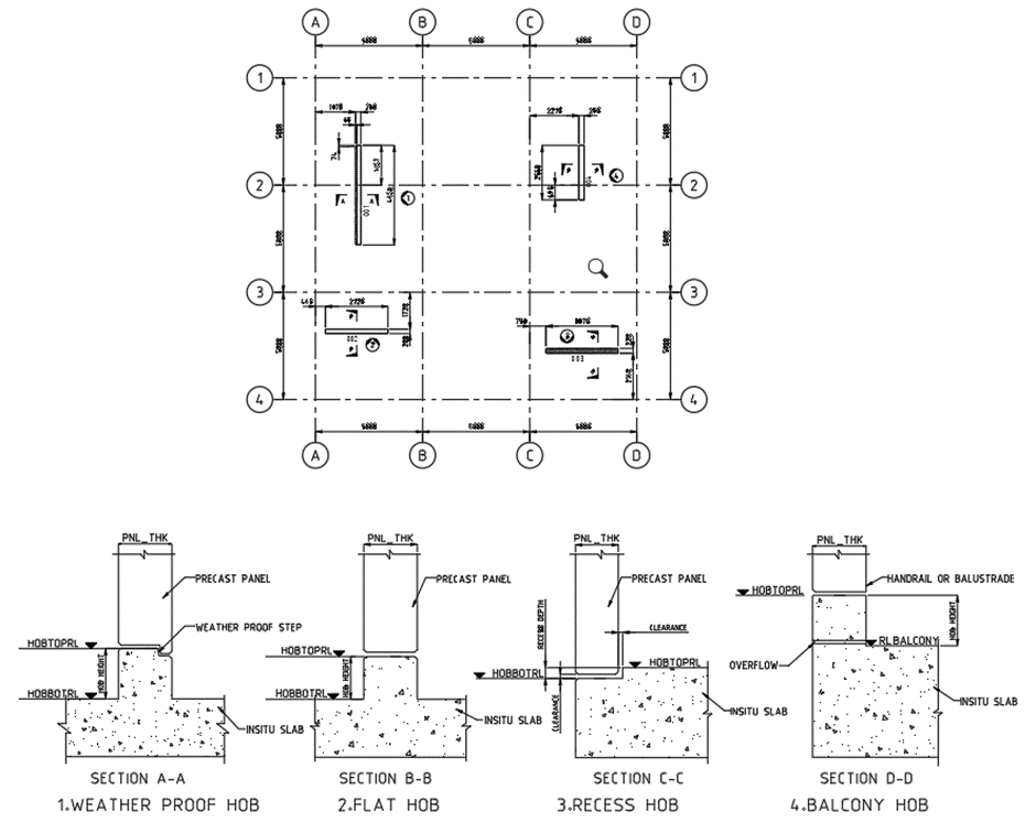
    Hob is projection or recess on the top of slab, which is made up of concreate or sometimes precast. It will act as a base or foot for the precast panels and balustrade which are to be placed above the actual SSL (Structural surface level) and a locating guide sometimes with weather proof.

    HOB TYPES

    1. Weather proof Or Stepped Hob:
          This type of hob has projection from slab SSL, which is used to separate inside (living spaces) and outside (balconies and wet areas) of the building to resist water to enter the building. It has recess at the outside of the building on top of the hob, which means top face has step along the outside of building. Refer Section A-A for weather proof hob.

    2. Flat hob:
         It is also projection type hob, but top face is in full width flat without step. Usually, it will locate between either inside-inside or outside-outside area. Refer Section B-B for flat hob.

    3. Recess hob:
      
      It is further back from SSL or ditch or recess on slab. It will also act as weather proof. This hob needs some gap clearance on the higher side to make easily sit precast on it. Refer Section C-C for recess hob.

    4. Balcony hob:
         
    Balcony hob also be the projection type; it is used to outside of the building in outermost wall to resist spill of water or use as balustrade. Balustrade purpose hob have considerably higher than the all-other hobs. Refer Section D-D Balcony hob.

    5. Model hob plan drawing:

  • Tek1 adds Revit and Tekla to precast Detailing

    Tek1 has extended their tool kit by adding Revit Structural and Tekla Precast to detail precast concrete.

    We were trialing precast for a few months now. We have developed some internal tools to handle precast panel shop drawing efficiently.

    Tekla for Precast

    We are experts in using Teka for steel detailing. Now are embarking on using Tekla for detailing precast. As first step, we have upgraded our 2 steel detailing Licenses in Melbourne to Global License and upgraded to enterprise. We are running parallel trials with Revit and Tekla to test whether Tekla will make the grade.

  • Revit Project Data and Parameters Populate in Title sheet


    Input Data

    • Project Details – Does the Revit file allow us to create Project Details. How and where is the data available to read?

    For Project information the details will be added and done in the Manage tab as shown below

    Step 1: Clicking to manage tab and click on the red clouded region as Project Information


    Step 2: Entering the Data about the Project as Shown above


    Step 3: Open the sheet family and click on the Shared Parameter Option in the Manage tab


    Step 4: Create the new parameter if needed and Create new group where the parameters are to be called for.


    Step 5: Add the new parameter in the Paremter property. Once parameter done it can’t be edited and it has to be removed and create a new one .


    Step 6: Now the “Drawing Status” Parameter are now called under the Parameter group exported parameter.


    Step 7: Click the Label Parameter to call the label that are already created in parameter


    Step 8: The parameter which was created in shared was not displayed so click on the add parameter to call from the group.


    Step 9: Click on the select button to call the shared parameter group defined.


    Step 10: Click on the required parameter to call and click on ok


    Step 11: The parameter which was not available in the list are now generated and called


    Step 12: The parameter which was not available in the list are now generated and called to edit parameter list


    Step 13: Then click the add parameter lab clouded in red and the following parameter will be added in the label and then click ok.


    Step 14: The Label “Drawing Status” was now added in the Sheet Family


    Step 15: Then click on the “Load into Project“ button to load the Shop Drawing Sheet in the Project.


    Step 16: The question mark we highlighted are the Parameter “Drawing Status” and it’s not editable at this stage because this shared parameter was not called in the Project Parameter. To sort this please follow the below steps.


    Step 17: Click on the project parameter to call the shared parameter we defined in Sheet family


    Step 18: Click on to add button


    Step 19: Click on to the shared Parameter and then click select button


    Step 20: Click on the Parameter you defined previously and need to be editable and click ok.


    Step 21: Once the shared parameter are defined on Project Parameter then click the Check box on the right end shown where the parameter to be display in your revit file and then click ok.


    Step 22: Now you can see the question mark colour changes from red to blue which is editable one.


    Step 23: The Parameters are added and edited in the Shop Drawing Title Sheet.


    Idea: If you like to make your visuals to find the parameter is in editable or not editable please do the following thing below

    Go to file tab and click on the option button below and set the graphics by changing the colours as shown below instead of same colour

    Thanks to Koshy, Ben ,Venkat and Parthee for Supporting and guidance .

  • Information Gathering for precast detailing from STRUCTURAL PLAN

    Here we are going to explaining about the thing needed to focus on STRUCTURAL PLAN for precast detailing

    • Width /Thickness of panel:
      1. Panel width and thickness should satisfy min structural requirement because structural engineer worked with that structural requirement of panel to provide building strength and stability. If we provide less than structural thickness and width then we cannot achieve strength and stability.
      2. Greater than structural thickness will come because of groove/pattern but it should not be less than structural thickness. (If groove/pattern returns on panel edge, raise RFI to confirm width extension). 
    • Mesh detail:
      1. Schedules created and specified its required type for each and every panel. Legend type need to take from plan and refer it with schedule.
      2. Refer reinforcement schedule if they provided or else refer handover reinforcement schedule. (if schedule missing please discuss with Builder)
    • Grade of panel:
      1. Mostly plans shows direct grade value of panels
      2. Schedules created and specified its required grade for each and every panel. Legend type need to take from plan and refer it with schedule.
      3. For spandrels, they will not provide any values. In that case use 40MPa grade.(UNO)
      4. For columns, shear walls and cores grade to be referred from its respective schedule.
    Fig: Structural plan showing Grade value
    • Load bearing/ Non- Bearing of panel:
      1. These are decided by engineers and specify on structural plans
      2. Generally precast panels are
        • Load bearing panel– Separate hatch will show or legend will show as LBP
        • Non-load bearing panel– Separate hatch will show or legend will show as NLBP
        • Partially load bearing panel-If they provided some distances only as LBP means then that remaining part of panel is non-load bearing. So that panel will be partially load bearing.
      3. In some special case if structural engineer instructs to refer any drawings, we must refer that drawing for NLBP/LBP region
      4. As default spandrels are NLBP but don’t show it on panels.   
    Fig: Structural plan showing LBP and NLBP
    • Slab thickness:
      1. Thickness of slab provided in this plan
      2. Extent of Folding on slab profile values also given in this plan
      3. For critical profile draw slab profile in 1:1 ratio
      4. If no step ups/down slab thickness provided, in that case use minimum slab thickness value along with step value. (If hidden line step occurs on under-side of slab and if continuous line step occurs on upper side) – Those details are clearly visible only on PDF.
      5. Stair landing slab thickness usually not given in stru plan, we need to refer that from relevant stru stair drawing
      6. Most of cases nominal slab thickness for particular level will be noted in its title sheet. So PDF reference is must.
      7. If Sectional details provided, it must be refer for additional information
    Fig: Structural plan showing Slab Thickness and Slab Folding
    • Temporary movement joint/construction joint:
      1. A line with legend for temporary movement/ construction joint shown in structural drawings
      2. We need to consider this while providing panel breakup because slab pouring sequence may change and it will affect panel
      3. In case no other way to provide breakup at those location, we need to detail our panel profile based on joint location
      4. It must be consider while providing props location/ GT breather face.
      5. Temp connection is not needed when precast seat on different pour.
    Fig: Structural plan showing Temporary movement line
    • Extra reo details :
      1. Sometimes structural engineer requires additional reo specification for certain panels
        • In this case they provide separate elevation with drawing number, we have to go through that elevation and provide reo for our panel
        • In plan itself they provided excess reo detail
        • Some indication will provide for additional reo detail and that relevant detail will be provided on title sheet.
    Fig: Structural Elevation showing for Panel Types
    Fig: Structural Wall Schedule for Precast Details
    • In-situ connection detail:
      • Precast that are connecting with in-situ will be highlighted in handover & structural drawings.(it differs only on some special cases)
      •  Separate drawings or sectional detail provided for connection between insitu and precast. We need to study and collect connection information from it.
      • If Precast connects with in-situ and connection details not provided means we have to raise TBC for it. 
      • If NLBP connects with in-situ we must confirm with Builder
    Fig: In-situ connection with precast panels
    • Slab profile type:
      •  Slab profiles are determined and highlighted in special legend.
      • Those determined profiles are classified as different types and provide it in a separate drawing
      • By study those type and legends sometimes we need take slab profile cut values and folding values for slab profile  
    Fig: Structural plan showing Special legend for slab profiles


  • Types of Brace (Prop) Plan

    Brace are used for temporarily support precast concrete elements until the permanent fixing are made.
    1. Single storey (Drop-in) panel propping
    2. Double storey (Spin-up) panel propping
    3. Panel higher than double storey propping
    4. Panel to panel propping
    5. Edge Propping
    6. Spandrels propping

    1. Single storey panel propping:
          Single story panel are normally used 2 props a panel. Some times more than 2 props are used based on panel design.

    2. Double storey panel propping:
         
          Double story panel are normally 2 props placed 200mm below the underside of slab. Some times more than 2 props are used based on panel design.


    3. Panel higher than double storey panel propping:
           This type of panel needs two level of propping. Two props on the below level and two props on the above level. If there is a slab in above level the propping system will pass through the below level slab by providing a pocket on the slab

    4. Panel to panel propping:
       
    Provide ferrule in the opposite panel Or Adjacent panel for propping. Especially this kind of propping system are applicable for lift and stair core area, where there will be no slab to support the prop.

    5. Edge Propping:

        These types of propping are used for column and some panel having cantilever. Provide ferrule in the edge of the panel.

    6. Spandrels propping:
       
    These types of propping are used for spandrels. Provide ferrule at the top of panel. Where the ferrule will be connected with the member which hold the propping system.

    Model brace plan drawing:


  • Information Gathering for precast detailing from Arch Conc Setout Plan

    Here we are going to explaining about the thing needed to focus on ARCH CONC SETOUT PLAN for precast detailing

    • Panel Set-out & width:
      1. Mostly we prefer to use Precast Set-out from Conc set-out but before proceed with this drawing , we need to raise RFI to Builder to confirm this Drawing need to follow for this entire project.
      2. If panel set-out, dimensions, openings annotate on conc set-out means use that value.
      3. Please look over for special indication that denotes architectural patterns

    • Slab RL:
      1. SSL value is provided on conc plan with respect to top profile of slab.
      2. Slab step downs/ step up profiles are specified in this plan by its RL values and some special legends

    • Slab thickness:
      1. Some architects, they clearly specify their slab thickness in concrete setout itself but we need to confirm that slab thickness with structural drawings.

    • Parapet/spandrels/window &Door RL:
      1. In most of the cases spandrels top RL specify in this plan
      2. In some case, for parapet wall (top of wall)RL should take from this plan
      3. In some case ,sill RL and header RL for window will be given in this plan
      4. In some case ,sill RL and header RL for door will be given in this plan

    • Overflow location :
      1. Overflow need to provide at balcony/terrace areas
      2. Location and size of those overflow can be taken from precast panels concrete setout
      3. If overflow location not provided we need to raise TBC for overflow location.

    • Slab / wall peno location:
      1. Penetrations are require to provide for varies purposes
        • Service penetrations at slab
        • Service penetrations at wall
      2. These penetration locations and sizes are need to take from this plan as well as elevation.

    • Profile Type:
      1. Slab profiles are determined and highlighted in special legend.
      2. Those determined profiles are classified as different types and provide it in a separate drawing
      3. By study those type and legends, sometimes we need take slab step ups/downs values and nominal folding values for slab profile.

    • Alimak /loading platforms/ Hoist locations:
      1. Those void locations are helpful in providing breakups and panel erection type
      2. Alimak are type of material transport car, used to transport building materials to all levels. Where alimak is present we can’t erect precast.
      3. If panel locate at alimak/loading platform /hoist, it will affect construction materials transportation.
      4. So some modification on construction process will require at those locations ,precast may also be changed to in-situ and some cases it can be as post –fixing panels
      5. Breakups also need to consider while doing marking plan.

    • Pattern Groove Set-out:
      1. Pattern groove set out – some rare case only, architect show pattern groove set out in conc plan. (Mainly refer architect elevation)
      2. If they provided it will more helpful in providing panel breakup, based on groove only we need to provide breakup for panels in continues elevation.

    • Ramp profile:
      • Ramp slab: Data’s provided for ramp in two ways
        1. Ramp profile increasing ratio (percentage) will provide between two points, length will be measured between those two points
        2. Starting point and ending point RL’s will provide between two points, length will be measured between those two points
        3. If additional ramp sections provided, then we also need to consider it.

                                 Above data’s will provide in conc setout plan. We need to take those data and work it out for exact ramp profile of slab


    • Slab boundary line:
      1. For slab boundary line, we need to refer slab extent in conc plan

  • Bubbledeck Slab Shop Drawing

    • Extraction of individual Bubble deck Slab  from Layout to Sheet
    • Calculation for Volume and weight for  minimum slab pour in Factory
    • Placement of Lifters on the Min slab pour to lift the Min slab after pouring and curing form the factory
    • Reinforcement setout panel copied from the Source panel
    • Reinforcement Arrangements are done based on the Original Slab depth value given to the copied panel
    •  Trimmer bars If the panel has Profile breaks and column Opening
    • Dimensioning of Panel ball set out for Panel Profile, Balls  and cast in components present in the Min Slab Pour
    • Dimensioning of Reinforcement set out for Slab cover from the start of reo bar.  Reinforcement setout Point selection and dimension for Truss arrangement.
    • Heading Notes for Panel ball set out with finish notes and Reinforcement setout
    •  Notes for Block out and Penetration in Panel Ball setout
    • Notes for Trimmer Bar , Splice Bar and Loose U Bars in Reinforcement setout
    • List part for the cast in Components present inside the min concrete Slab

    Thanks to Koshy, Ben and Venkat for Supporting and guidance .