Category: Precast Blogs

Tek1 has detailed over 100,000 precast panels over 19 years.
over 90,000 were detailed under a proxy name Advanced Pretty Pictures Pty Ltd

PRECAST PANEL DETIAILING
EXPERT PRECAST PANEL DETIAILING
  • Detailing Keys for Profile Spandrels, Shape columns in Precast concrete

    Steps involved in shop drawing created from Mould

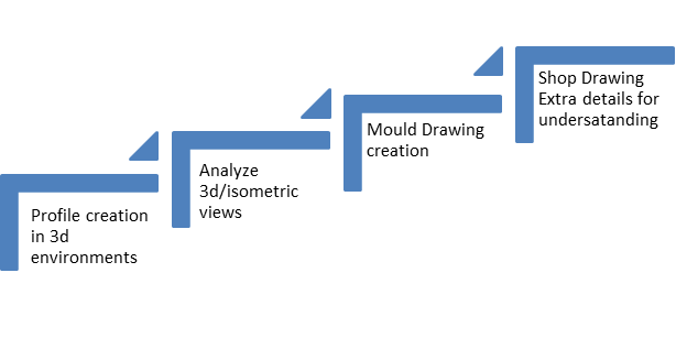
    Process flow 

    1. Profile creation in 3d environments
      • We want to understanding the shapes , If we draw the 3d models clarified with the visuals, So we do profiles in 3d
      • 3d model views are easy to understand the Profiles & more clarity
    2. Analyze the 3d/isometric views & clarity dimensional sections in shop drawings
      • After finishing the model cross check the Profile clash, component clash, Perpendicular views & its properties.
    3. Mould creation
      • created the mould for all the shapes.
      • Get advice from the factory those who are making the mould for this shape of panels in precast concrete.
      • Finalized the mould drawings.
    4. Shop Drawing details for understanding
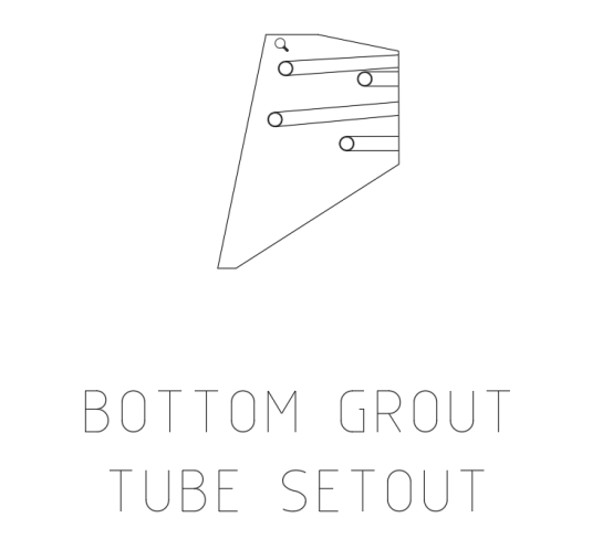
      • Grout tube setouts
      • Profile setouts
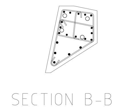
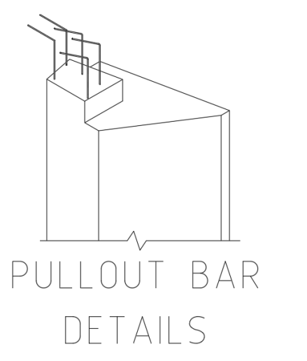
      • Reinforcement clarity section & Isometric views

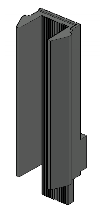
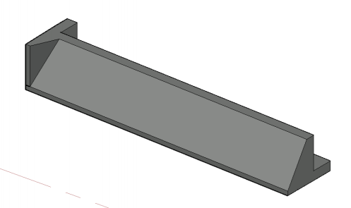
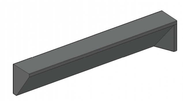
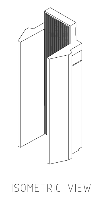
    Shapes of the Precast in 3d Model


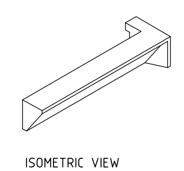
    Isometric views shown in shop drawing for clear understanding


    •  

    Final output of the building is


  • Information Gathering for precast detailing from consultant drawings

    Precast detailing is the process of create detailed drawings of each component in precast. The precast drawing is responsible for extract structural design calculations and Architectural innovative.

    Precast detailer utilises Architectural, structural and services drawings to gain a working knowledge of the overall design intent of the building. precast detailers will draw the precast detailed drawing with refer Architectural, structural and services with some technical standard to achievable manufacturing, transport ability and Build ability

    So detailer should aware about the information Gathering from consultant drawings to precast detailing

    Here we are going to explaining about the thing needed to focus on ARCH GA PLAN for precast detailing


    ♦ Viewing direction:

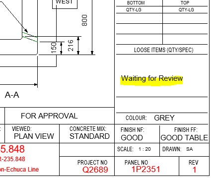
      1. Viewing direction should be from INSIDE of building (i.e. should not view from Visible side of building) because panel FAR FACE should be at TABLE FACE to get GOOD TABLE finish. Based on Finish purpose and mould similarity we can also view from outside of building
      2. But we need to consider some conditions here
        • Up stand/corbel /crank profiles are quiet difficult to cast in far face so viewing direction need to place based on to match those profile comes at NEAR FACE
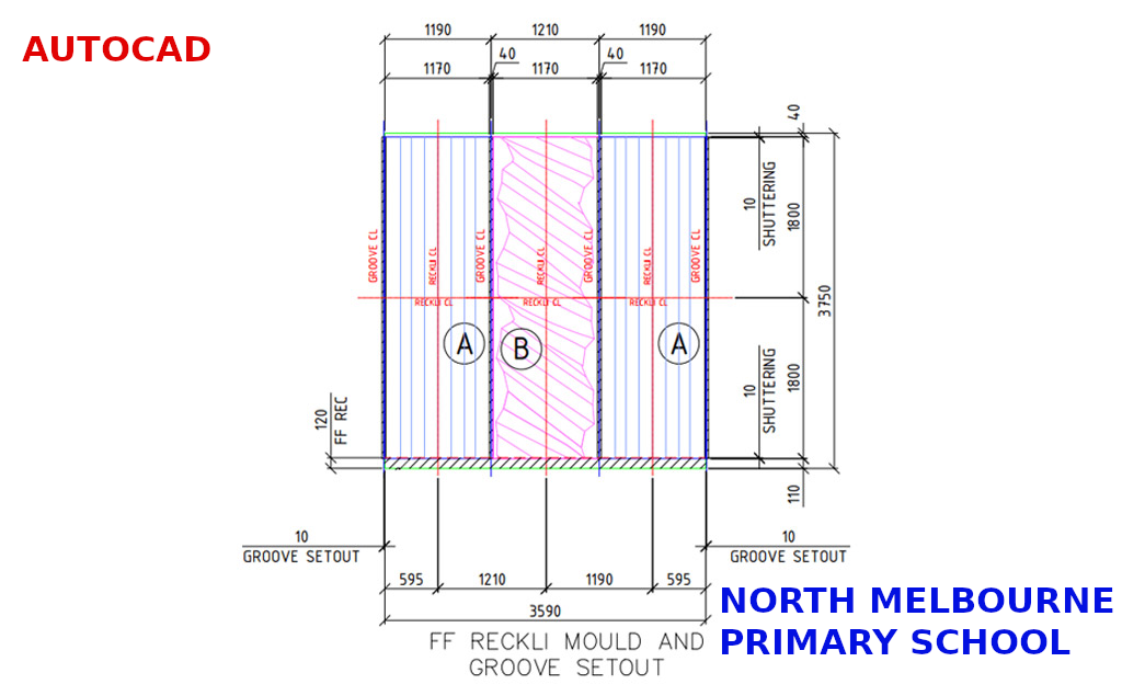
      3. Architectural pattern(e.g. Groove, Reckli, Brick snaps etc.) always try to place FAR FACE,

    Note: Study all levels before provide viewing direction of panel at bottom level because once direction provided it should not be changed for that elevation until end of that panel.


    ♦ Finish:

      • NF Finish – Trowel, Semi Trowel, Float, Polished, Broom or Custom
      • FF Finish – Table, Good Table, Reckli, Polished, Retarder, Patterned
    1. Mostly we use Trowel and Float finish, Good table
    2. Other type of finish used only when clients special requirement
    3. Study GA PLAN or WALLS drawings and provide trowel finish at visible area.
    4. Refer Arch Elevation for additional finishes and pattern requirements, if any things specified in handover

    ♦ Inside and Outside:

      1. Study GA plan based on general arrangement on plan like bedroom , balcony ,corridor living room , study room , Lift area , stair area etc.
      2. Provide visible places/outside of building as Outside and Non visible places/ inside of building as Inside.
      3. If given OUTSIDE, factory will take additional care for finish.

    ♦ Weather proofing:

    1. Weather Proofing for a panel provided based on panel locate at below condition
      • Inside / Outside – weathering require
      • Inside / Inside – No weathering require
      • Outside / Outside – No weathering require
    2. By considering inside and outside location of panel and arrangement on GA plan provide weathering and return values for panel
    3. Provide weathering at window sill level and lintel level.
    4. Provide weathering at spandrels if bottom area covered with window

    Mainly weather proofing is used to terminate fluid flow into the building


    ♦ Exposed edge:

      1. Study GA plan and provide Exposed edge at visible edge of panels like outside edge of panel, door & window frame openings and top of panel which are visible
      2. Service openings on panel also need to provide exposed edges(Not require for small penetrations)

    ♦ Horizontal Groove requirement :

      1. For spin-up panels present at visible area of building we need to provide HORIZONTAL GROOVE to match adjacent drop-in panels breakup or some case good visibility purpose.
      2. We need to raise RFI to confirm those groove requirement to follow for that entire project
      3. Edge Groove or Return Groove requires only when FF groove continues and also comes at NF (NF visibility at outside). In these cases NF groove usage need to confirm with Builder.

    Study GA plan and provide as per requirement of that panel location.


    ♦ FSL RL detail:

      1. In some projects they clearly specify FSL- FINISH SLAB LEVEL RL in GA plan.

    Take that value from GA plan and use it while detailing Overflow, & Lift Door opening.


    ♦ GT breather face:

      1. Breather face provided based on slab access- Should not provide no slab access face
      2. Perpendicular walls/ panels clashes – provide GT extension if clashes with it or else change face if both sides are trowel finish
      3. NF/FF Finish of panel-avoid breather on exposed face(visible face)
      4. Breather must not provide at arch pattern face

    Its Easy to manufacture breather face locate at FF/ TABLE FACE


    ♦ Prop face :

      1. Recess for prop provide based on finish for that we need to refer GA plan
      2. Prop face provided based on slab access- Should not provide no slab access face
      3. Perpendicular walls/ panels clashes – change or move prop location if not provide suitable prop type
      4. Check with structural /Arch conc setout to find prop not locate at slab penetration location
      5. Check with PT drawings to find prop not locate at PT stress pan

    Its Easy manufacture PROP face locate at FF/ TABLE FACE


    ♦ Door and window openings:

      1. If No Door/ window schedules provide for that project we need to refer location and size of door / window form GA plan and must confirm with Builder.
      2. For height, manually calculate height from CAD elevation file and ask TBC with Builder.

    ♦ For extent of arch pattern refer GA plan wherever applicable

    Note: – In next session we will focus on Information Gathering from ARCH CONC SETOUT PLAN to precast detailing.it will be post ASAP

    Thanks to Ben for supporting me in blogging login & posting, special thanks to Koshy & Venkat for supporting on this document & regulatory me 

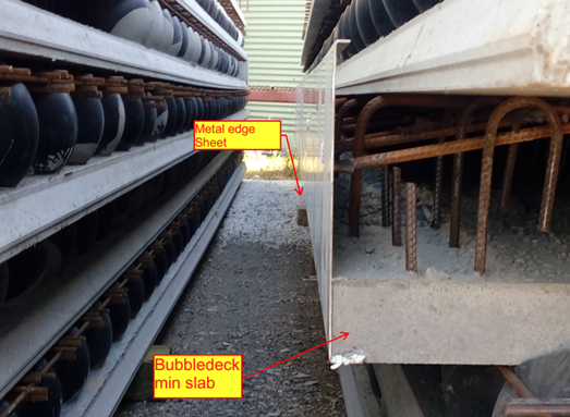
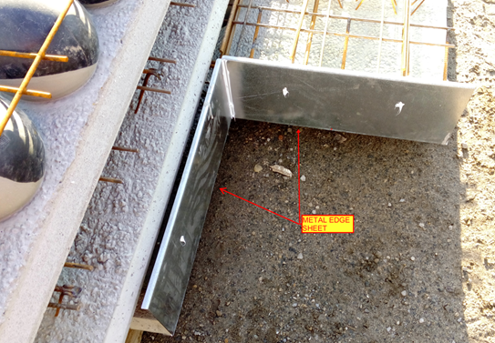
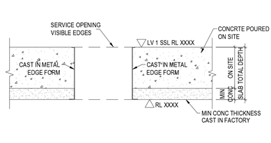
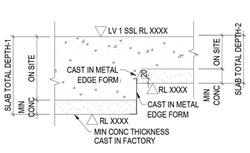
  • Metal Edges in Bubbledeck Slab

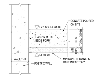
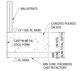
          Metal edge is the 2mm to 3mm thick Galvanized Sheet which are mainly placed in the building edges of the Slab to stop the overflow of concrete while pouring on the Bubble deck Slab arrangements.

         Metal edges are fixed in the factory and not on site; it will be fixed while pouring the minimum thickness concrete slab biscuit. So the metal edge are comes under the category of castin items in Bubbledeck Slab.

    Application of Metal edges:

    • Bubbledeck Slab Edges  that connects to Post fixed precast wall (Post fix wall will be erected once after the bubbledeck Slab are installed and Poured).
    • Slab edges which are free from the wall. Especially near to balustrade Areas
    • Duct and services void in slab which is present  inside the Building
    • Soffiit Step / Slab fall in slab

    Advantages :

    • Fine Finish of slab edge (Visible edges) can be obtained
    • No side shuttering is needed
    • Site work can be reduce due to fixing in factory long with min concrete Slab pouring

    Disadvantages:

    • The cost of Metal edge sheet is high compare to timber because of galvanized
    • The metal edge to be order 10 days prior from casting on minimum concrete because of sheet galvanizing

    Handling Problem:

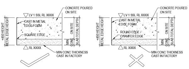
      The Metal edge is not safe to use 450mm and above height. This may lead to bend and damage of metal edge sheet during the time of Bubbledeck Biscuit Transportation.

      The Metal edge can’t be fixed on the round edge profiles of slab and applicable only for square edge Profile.

  • Precast Bubbledeck Slab Casting Process

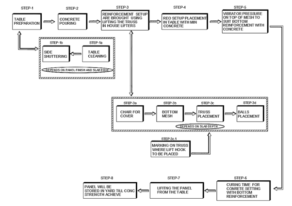
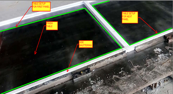
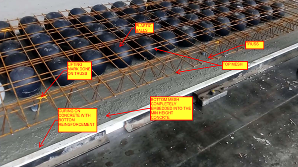
    STEP 1: TABLE PREPARATION

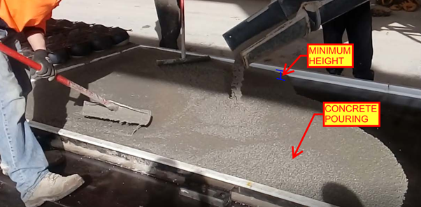
    STEP 2: CONCRETE POURING IN THE TABLE

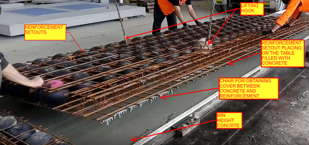
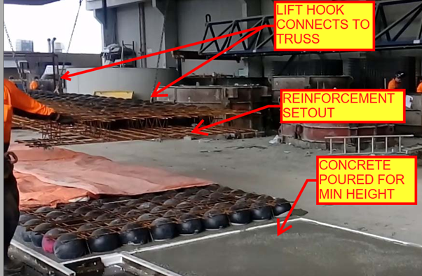
    STEP 3: REINFORCEMENT SETOUT LIFITNG USING IN HOUSE LIFTERS

    STEP 4: REINFORCEMENT SETUP PLACEMENT IN TABLE WITH MIN HEIGHT CONCRETE ON IT

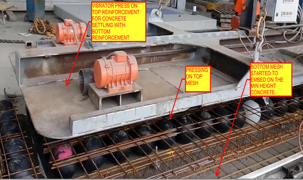
    STEP 5: VIBRATOR PRESSURE ON TOP OF MESH TO SUIT BOTTOM REO WITH CONCRETE

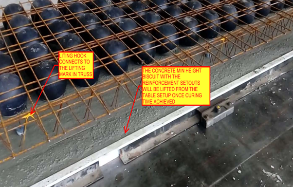
    STEP 6: CURING TIME FOR CONCRETE SETTING WITH REINFORCEMENT

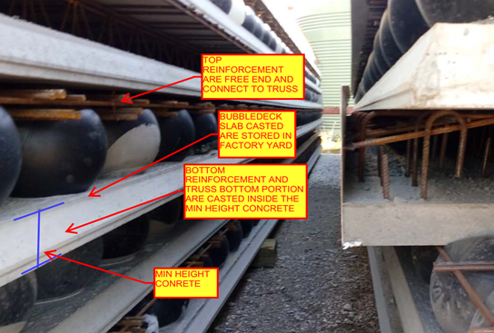
    STEP 7: LIFTING THE PANEL FROM THE TABLE

    STEP 8: PANEL STORED IN YARD AFTER CASTING COMPLETED

  • Bubble deck Slab

    What is Bubble deck Slab?

            The slab that comprises of plastic void balls in middle which are sandwiched between top and bottom mesh to reduce the dead weight act on the slab

            It is a biaxial hollow core slab where the concrete which is not performing any structural function are eliminated lead to reduction in 30% to 50% of its slab weight

    Principle:

         The Hollow plastic balls clamped with the top and bottom reinforcement are placed in the thin concrete of 60mm with max length and width of 10m x 3m to form a precast setup will be done in factory. After that the setup will be installed on site with connecting rods and by pouring concrete

         The 35% saving in concrete composition was achieved by the ratio of Plastic ball diameter to the thickness of the slab depth

      The reduction in slab weight leads to achieve the Load bearing capacity at a smaller slab thickness result in saving 40 to 50% of material consumption per Floor level.

    Materials for Bubble deck slab:

    Concrete

    • Standard with max aggregate size of 20mm
    • No plasticizers needed for concrete mix
    • Grade of concrete must be above M30

    Reinforcement

    • Grade Fe-600 strength or high
    • Top mesh and Bottom Mesh reo of N12 bars max
    • Truss arrangements for vertical support of balls. Truss height depends on slab depth

    Plastic Balls

    • Hollow sphere Plastic balls made of Polyethylene
    • Diameter of balls are depends on the Slab Depth. Ball sizes are 180mm, 225mm, 270mm, 315mm and 360mm.

    Applications of Bubble deck Slab

      Superior Architectural Design

    • Free choice of shape
    • Large corbels
    • Large spans and cantilever
    • No beam and fewer column results in flexibility
    • Interior design can be easily being altered.

    Advantages:

    Structural

    • Reduce the foundation size since 50% of the dead weight is already reduced by the slab.
    • Increased Strength due to biaxial Loading.
    • Longer spans are supported since no bean is required.
    • Column count can be reduced.
    • Excavation required less work.
    • Conduits and openings for service ducts can be easily incorporate in factory.

    Construction

    • Less equipment is required due to light in weight.
    • Less work on Site construction.
    • Shuttering work and its Dismantling is not required since the 60mm concrete biscuit will act as shutter.
    • Construction hours and time taken is very less compare to conventional Slab

    Engineering

    • High resistance against explosion due to biaxial flat slab system.
    • High Resistance to earthquake due to slab acts as elastic vertical structure.
    • User friendly to Post tensioning if running through slab.

    Environment

    • CO2 emission due to concrete manufacturing quantity are reduced
    • Less material consumption
    • Less energy consumption
    • Less wood as no horizontal scaffolding

    Economy

    • Sustainable for easy installation
    • Made to measure and saving material
    • Fast Implementation and construction
    • Reduction in Transportation Loading cost.
    • No shuttering  and its cost needed

    Disadvantage

    • Deflection will less higher than the Conventional Slab
    • Load carrying Capacity is lesser than the Conventional slab
    • Skilled labour required
    • Shear Load design consideration and its  factor near the column area to slab care is required

  • Precast Panel (Irregular Profile) while lifting from Mould Study Using Miniature Prototype

    Today we are going to show the miniature Prototype we done on the precast panel and its mould using a 3d printing device.

            By preparing miniature we have come across the difficulties and problem that happen during the realistic bound assembly of sheet metal joining for mould and removal of Panel from the Mould setup after the panel casting work completed.

           In this case study we will show how the panel removed from the mould set after casting completed by miniature prototype setup

    Why Mould needed for this Panel

          Normally for rectangular liner profile precast tilt-up panel construction the casting bed with side shuttering   will be used.

     Material: Shuttering will be done either in timer or Aluminium Frame

            The panel profile faces are sloped or nonlinear and in order to maintain accurate panel profile we need to prepare a separate mould to cast the panel as required.

    Material: Mould profile will be done either in Steel Sheet (3mm) or Plate (8mm)

    Why Miniature Prototype creation

        The main theme of creating a miniature Prototype is by scaling the real time object to check the difficulties and issues that might happen during the process of preparing the Mould and casting the panel with it. By doing this we will be aware where the issue arises and how it can be fixed, so that the cost and time incurred during the real time casting will be resolved.

    Process of creating Miniature Prototype Creation

    Inference

            During the process of lifting the panel from the mould, the inner facing splay edges of panel will lead the panel to stop lift from the mould. To overcome this issue one of the inclined splay faces had to be adjustable one (non-permanent fixing) So that after the curing of panel the Mould face will be dismantles to lift the panel from the Mould.

         Please see the below Miniature Prototype video of lifting the panel from the Mould after casting done.

    Minature Mould – Bathers Way from Tek1 on Vimeo.

    Miniature Mould (Panel Lifting) – Bathers Way from Tek1 on Vimeo.

    Idea

       The panel has been poured in the Mould Miniature Prototype using Concrete cement with Miniature Reinforcement setup to check further if the panel is all good during the process of casting the panel and the extraction panel from the Mould after the Concrete are cured.

    Pouring the concrete (Bathers Way) from Tek1 on Vimeo.

    Extract concrete from mould (Bathers Way) from Tek1 on Vimeo.

    Acknowledgement   

    Special thanks to Parthee and Marimuthu for supporting during the Panel Miniature Casting. Thanks to Anandkumar for supporting in Miniature Mould assembly .Thanks to Ben for Supporting in content creation and blogging. Thanks to Koshy , Venkat for providing knowledge towards this idea and help to bring  as reality

  • Internal Processes

    Please find below the processes we expect all staff to follow:

    • Document all instructions in writing.
      • Why? Clients may call on the telephone. Communication may be confused. People say the wrong lengths, the wrong drawing numbers, and they might be working of the wrong revisions, and people hear the wrong things. If you receive instructions via the phone: put it in writing with any applicable mark ups to make sure that everyone is on the same page. Later on, if there is some miscommunication, it becomes a “he said – she said” blame game. We want to solve our clients problems not add to them.
      • Insist that communication is sent to the right people. If important communication is sent to the wrong person: perhaps a mark up or an RFI etc. then there is a chance that it could be missed.
    • Do not issue IFC drawings without IFA approvals.
      • Why? Clients will scream that they don’t care about approvals: but approvals are very important from a safety point of view. Be firm and clear: no IFC without IFA approvals. If a client wants to take a risk and build off an IFA drawing that that will be their prerogative. We do not want to risk someone’s safety in order to expedite a construction schedule.
    • Clear all outstanding RFIs before issuing drawings:
      • Why? If you don’t have the answers to the questions you need: then you can’t draw something on assumptions. What if those assumptions are not correct? Seek the answers you need before issues drawings.
    • DO NOT RUSH a job. Do it properly rather than do a rushed, or half-complete job.
      • Why? Because you will be likely to make mistakes and cost everyone even more down the line. If a client wants a ferrule moved on a mark up immediately, when there are 10 other items that need to be moved and verified, tell the client to wait. Because if those drawings are sent through, then you’ll need to send them again with those secondary revisions, and that will likely confuse people and cause huge problems down the line. Finish the job, do it properly and move on. Don’t be pressured to deliver a shoddy work due to time pressures. Yes we are all pressured by time, but there’s no point doing it badly and then costing everyone going forward.

  • How does Tek1 do Bubble Deck? Our Shop Drawing Processes

    Sample Drawings

    The best way is via demonstration. Please see some of the video demos we have put together. It is not by accident that our drawings come to you quickly. There are 10 distinct stages. We will upload the rest of the stages as we get and when we get an opportunity.

    The full list is here:

    Many commands do not have any video documentation attached. Some of the ones we have are documented below:

    We have updated our Insert Panel Lifters command:

    Dimension Tooling

    1 – Layout Commands

    enter help info here

    2 – Shop Drawing preparation

    3 – Bill of Materials

    4 – Dimension Panels

    enter help info here

    Insert Blocks

    enter help info here.

    Utilities

  • GrabCopy Demo – Precast Tooling Capabilities

    Grab Copy Demo from Tek1 on Vimeo.


    This is a work in progress demonstrating our capabilities and what we can do re: shop drawing.

    This is a work in progress. We will Improve and update these tools and code.