There’s nothing more satisfying than seeing our projects come to life. Witnessing the tangible results of our hard work, creativity, and meticulous planning fills us with immense pride and happiness.
From Design to Reality
Every project begins as a vision from our clients. Through detailed planning and precision engineering, we transform these concepts into reality. Overcoming challenges and refining designs, we ensure every detail meets our client’s expectations.
The Moment of Realization
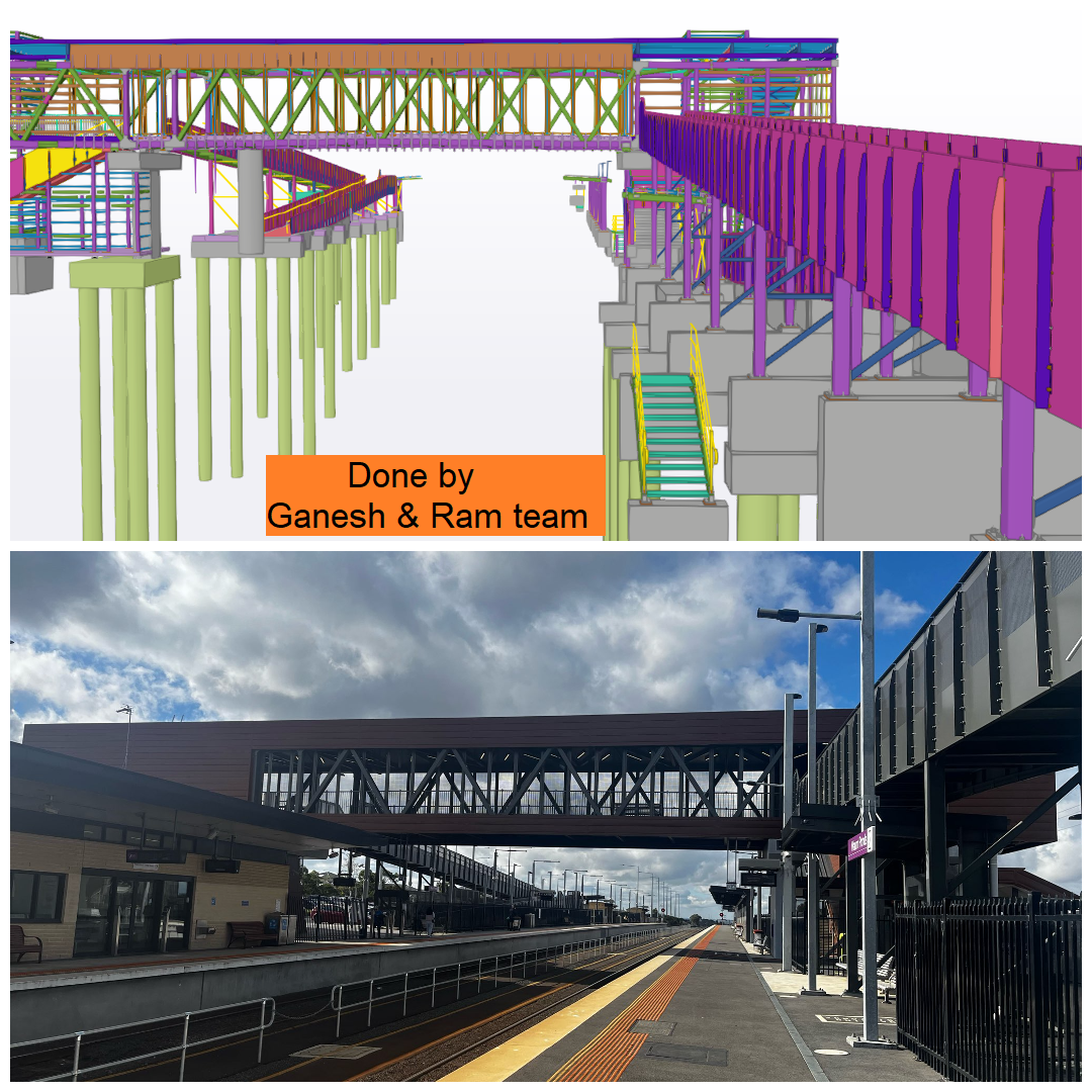
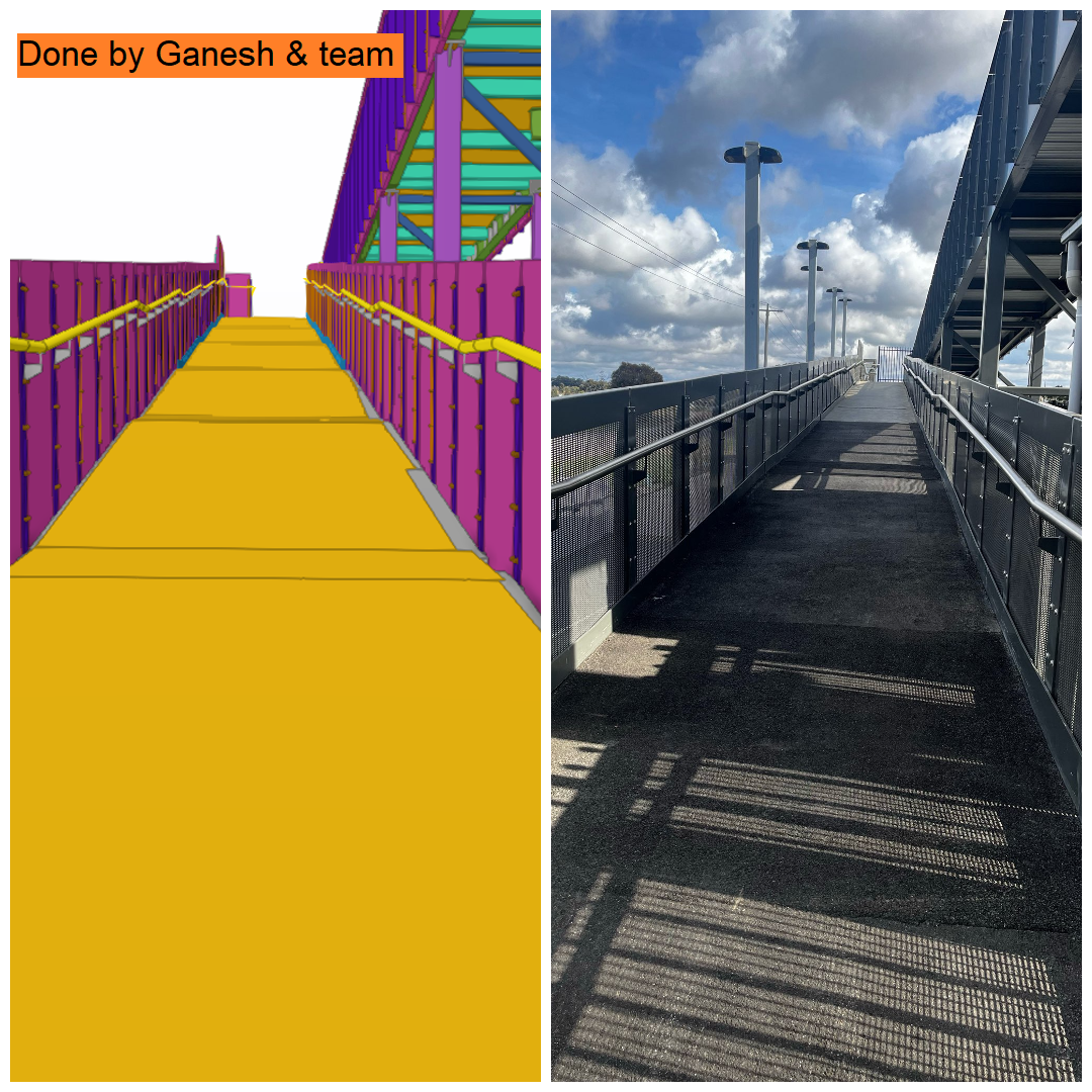
Seeing a project transition from a digital model to a physical structure is magical. It’s when the abstract becomes concrete, validating our hard work and dedication.
Why It Matters
Client Satisfaction: Ensuring our clients are happy with the final product.
Validation: Seeing the results of our hard work in the real world.
At TEK1, our extensive experience in detailing bridge projects has equipped us with the knowledge and foresight to minimize rework. Recently, we have been detailing two bridges for a leading company in Australia. Here’s a glimpse into how our expertise can prevent costly mistakes and ensure smooth project execution.
Addressing Cladding Design Challenges
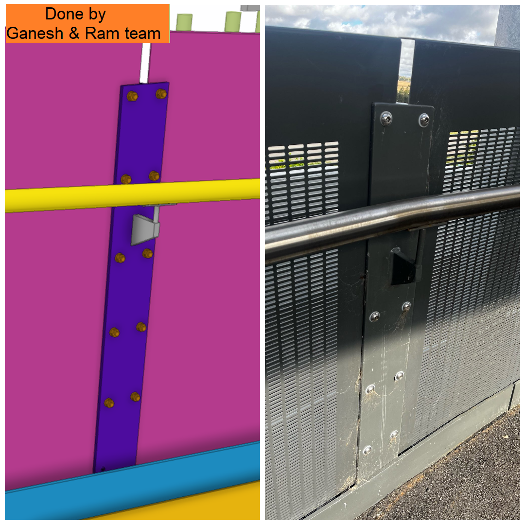
We received design drawings for the cladding around the bridges, one of which showed cladding with only one horizontal split at the bottom location, while the rest was a single piece. However, to facilitate easier handling and reduce the risk of damage, we identified the need for two horizontal splits instead of one.
Why Split the Cladding?
Handling Issues: Large, single-piece cladding can be difficult to manage in the shop.
Material Sensitivity: The cladding is made from a small aluminum sheet with perforations, making it prone to damage.
When modeling this type of cladding, it is crucial to consider the fabricator’s handling challenges and potential issues they might face.
TEK1’s Proactive Approach
Given our extensive experience with similar bridge projects, we anticipated these issues. TEK1 arranged for our detailers to visit the factory directly, allowing them to understand firsthand the difficulties fabricators might encounter.
For this particular bridge job, TEK1 proactively raised queries about the maximum length of the cladding before starting the project. By addressing potential issues early on, we can significantly reduce the risk of rework.
The Benefits of Experienced Detailing
By leveraging our experience and proactive approach, TEK1 ensures:
1. Enhanced Efficiency: By identifying and solving potential issues early, we streamline the fabrication process. 2.Cost Savings: Minimizing rework leads to significant cost savings for our clients. 3.Quality Assurance: Ensuring that the design is practical and feasible reduces the likelihood of damage and maintains high-quality standards.
At TEK1, our goal is to deliver projects that not only meet client requirements but also stand the test of time. By understanding and addressing fabrication challenges, we ensure that our detailing work is both precise and practical, ultimately saving time and resources for everyone involved.
Stay tuned for more insights and updates on how TEK1 continues to lead the way in bridge detailing and beyond.
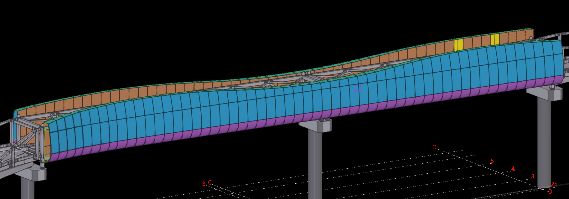
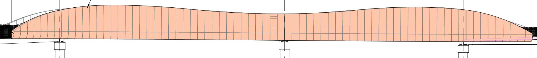
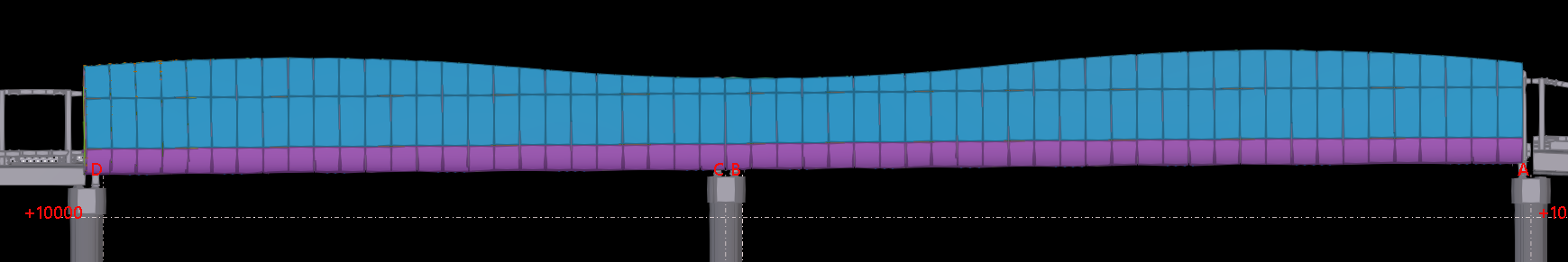
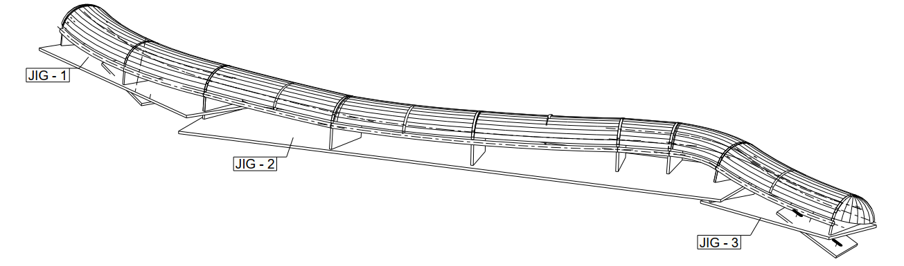
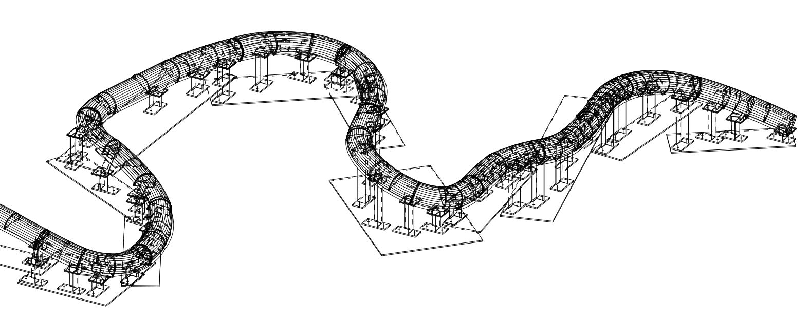
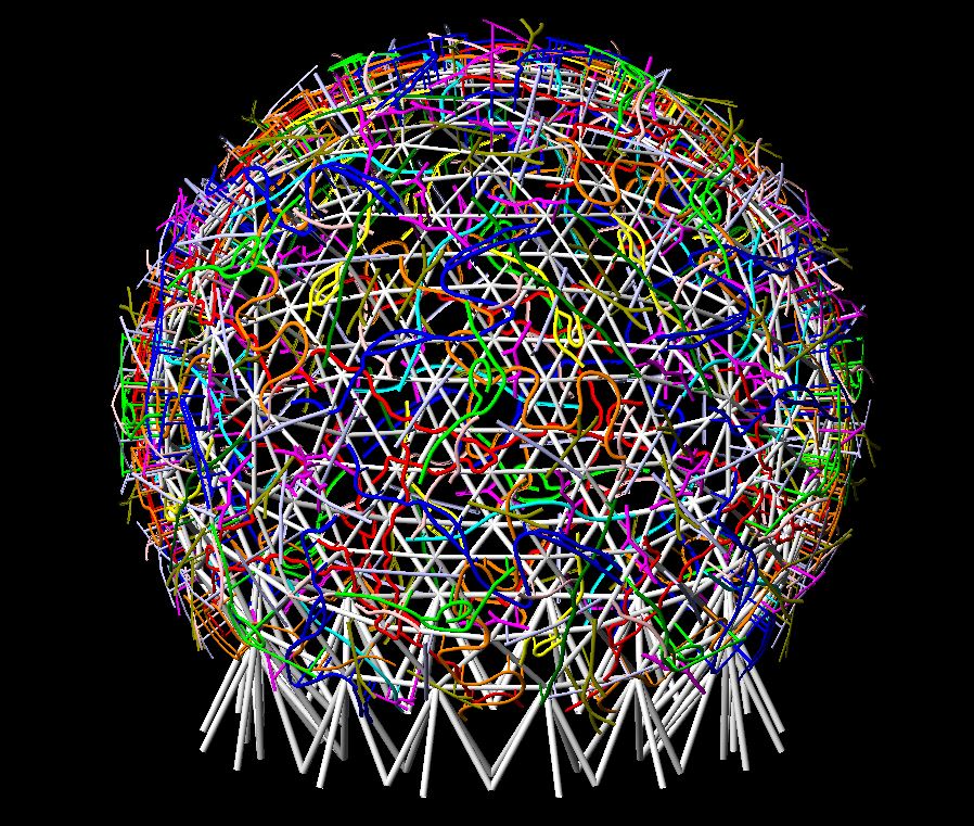
We are detailing the Australia iconic project EMU IN THE SKY.
There are branches everywhere around the globe. But none of them are straight. They are in different angle and different curves.
Initially, we proposed creating molds for each branch type to make this branches shape, but the client preferred using jigs for shaping.
Our Solution: Angles and Plates for Jigs
After careful planning, we suggested using angles and plates for the jigs due to their:
Availability and Cost: Easily available and more affordable than other profiles.
Reusability: The jigs can be reused, enhancing cost-effectiveness.
Our client accepted this approach and is now in the process of creating the jigs.
Skilled Craftsmanship
Creating these jigs is not a structural task but requires the expertise of a skilled detailer. The precision and craftsmanship involved ensure that the branches meet the project’s aesthetic and functional requirements.
Project Progress
As the project is still ongoing, we are unable to showcase the complete picture of the branches. However, we have provided some images from our model for your reference.
Our Commitment
At our company, our primary aim is to satisfy our clients’ requirements. Equally important is our commitment to minimizing costs and rework, which ultimately supports our goal of client satisfaction.
Stay tuned for more updates on the EMU IN THE SKY project as we continue to bring this iconic vision to life.
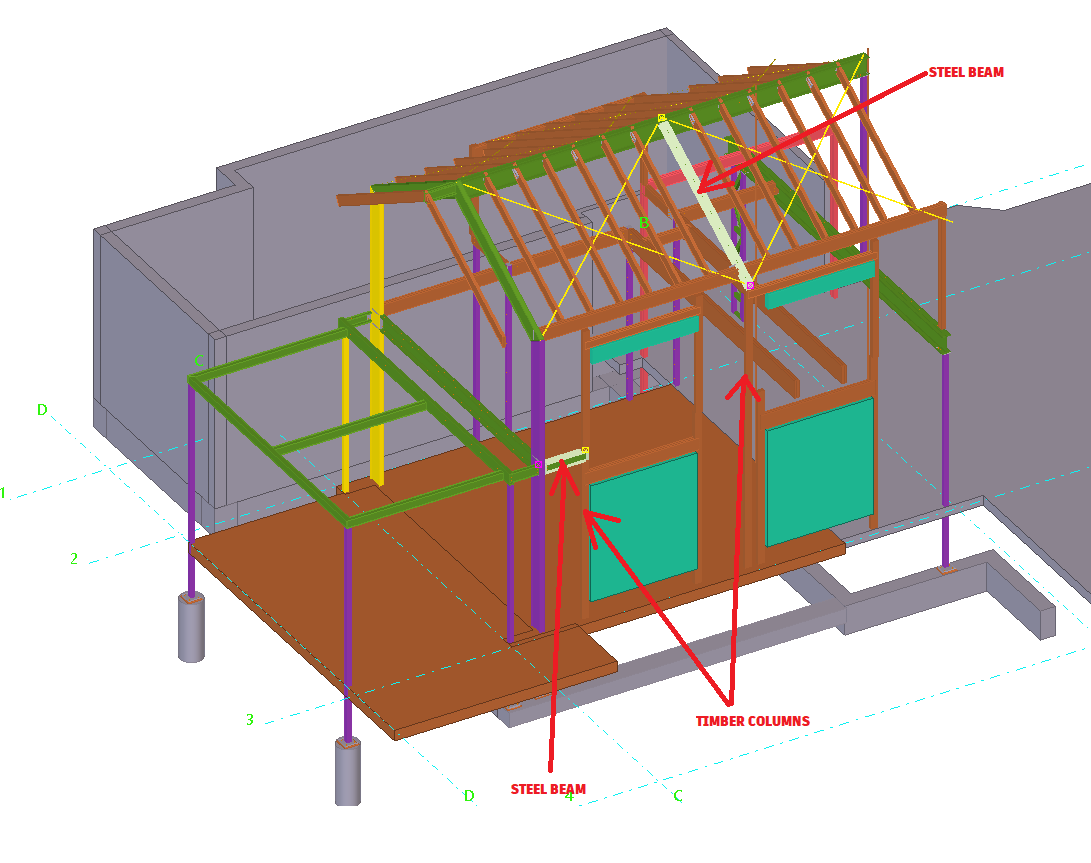
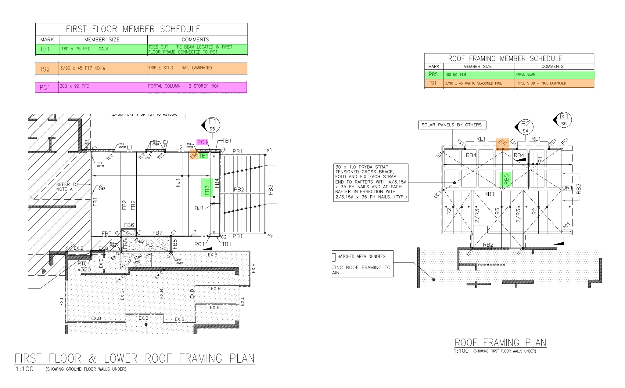
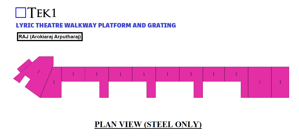
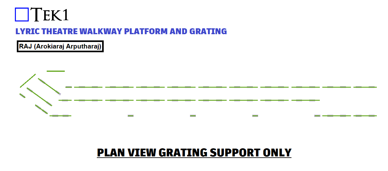
At TEK1, we recently took on an exciting project at 14 Ridgeway AV Kew. This project is a testament to our commitment to delivering innovative solutions in steel detailing. During the design phase, we identified a potential erection issue involving the use of timber columns to support steel beams. Our proactive approach led us to recommend a change that would streamline the construction process and enhance the overall efficiency of the project.
Project Overview
The 14 Ridgeway AV Kew project involves the construction of a structure where two steel beams are supported by timber columns. This design posed a significant challenge: coordinating the efforts of two different types of erectors—one for steel and another for timber. This not only complicates the erection process but also introduces potential delays and additional costs.
Identifying the Issue
As steel detailers, our primary goal is to ensure that every aspect of the project is executed smoothly. We quickly realized that having two different erectors on-site to handle the steel beams and timber columns would create unnecessary complications. The need for precise coordination between the steel and timber erectors could lead to scheduling conflicts, increased labor costs, and potential delays in the project timeline.
Proposed Solution: Steel Columns
To mitigate these issues, we suggested replacing the timber columns with steel columns. This change offers several advantages:
Streamlined Erection Process: With steel columns, a single erector can handle both the beams and the columns, simplifying coordination and reducing the risk of delays.
Enhanced Structural Integrity: Steel columns provide better support for the steel beams, ensuring a more robust and reliable structure.
Cost-Effective: By minimizing the need for multiple erectors, we can reduce labor costs and improve overall project efficiency.
Consistency in Material: Using steel for both the beams and columns ensures uniformity in the materials, which can lead to better performance and durability over time.
Client Approval and Implementation
We presented our recommendation to the client, highlighting the benefits of using steel columns instead of timber. The client appreciated our foresight and agreed to the change. This decision not only simplified the erection process but also contributed to a more streamlined and cost-effective construction phase.
Conclusion
At 14 Ridgeway AV Kew, our proactive approach and attention to detail allowed us to foresee potential issues and implement effective solutions. By suggesting the use of steel columns, we ensured a smoother erection process and enhanced the overall quality of the project. At TEK1, we are dedicated to delivering excellence in steel detailing and construction, always putting our clients’ best interests at the forefront of our projects.
Stay tuned for more updates on our innovative solutions and project successes!
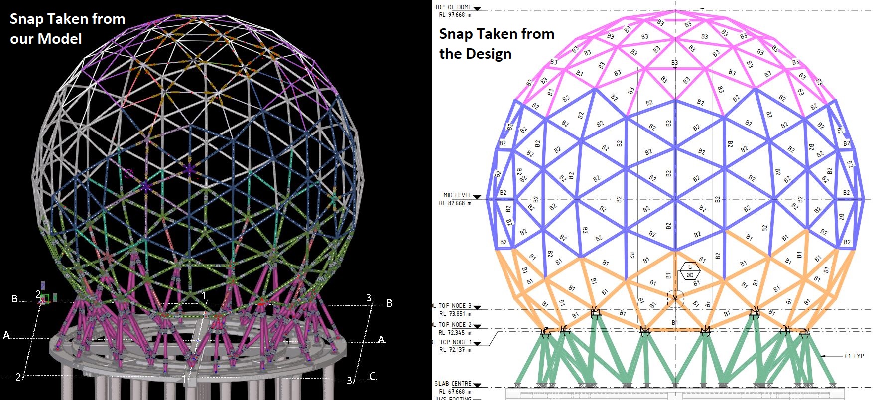
How we saved our 30% (i.e. hundreds of thousands of dollars) in Costs on the “Emu In the Sky” Project
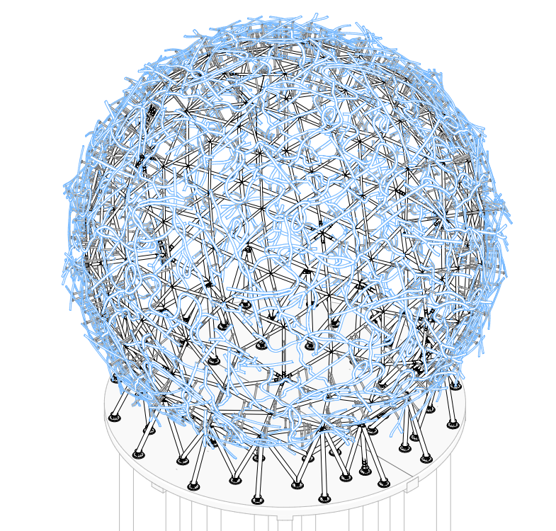
Recently, we have been detailing one of Australia’s most iconic projects, the “EMU IN THE SKY.” The structure of this project is a 30m globe, and as part of the steel detailing, numerous connections are involved.
How did we do it?
TEK1 has proposed
several solutions for the connections required.
proposed as easy way to acheive more accurate fabrication
Reduce Fabrication Time
and ultimately saved the client in the order of hundreds of thousands of dollars.
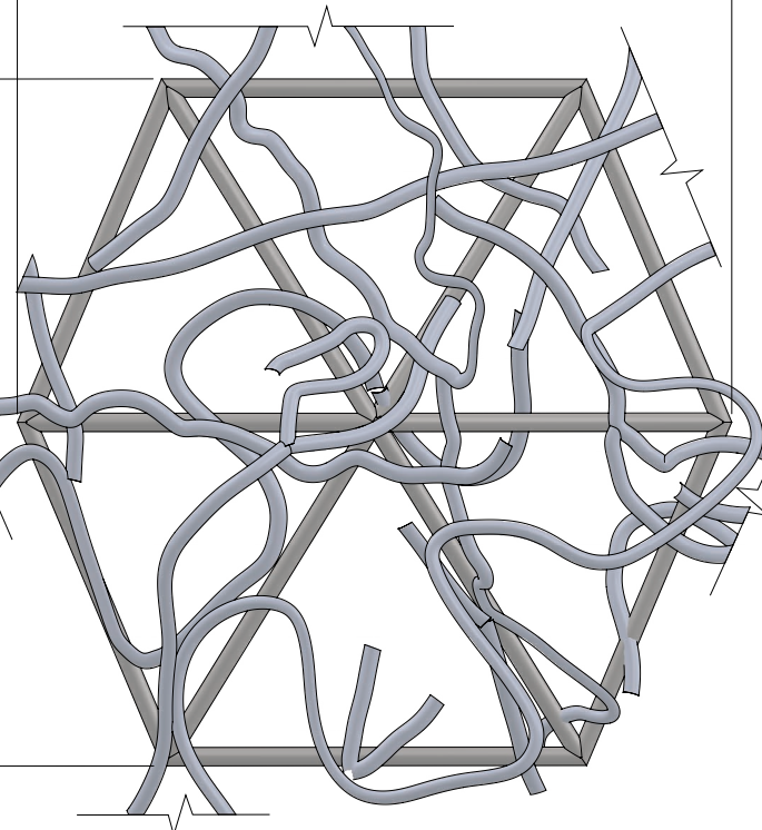
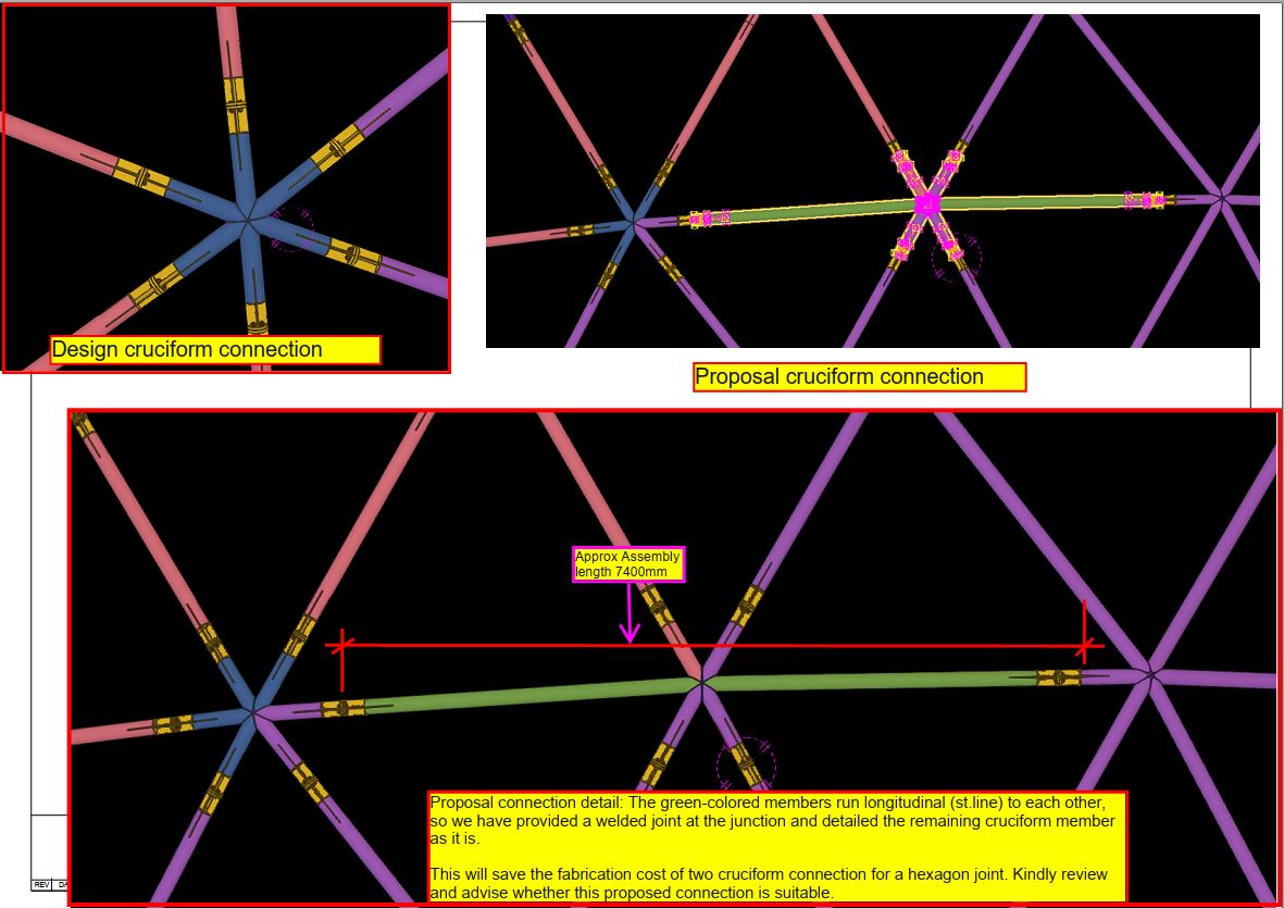
Hexagon Joint Connections:
The Problem
This design contains numbers of Hexagon join involved & it required six cruciform connections per hexagon joint. The weight of one Cruciform joint is 60-70kg approx
The Solution
The TEK1 Team (Ramakrishnan)proposed an alternative solution that reduced the number of cruciform connections required for a hexagon joint..
By implementing our proposal, we eliminate two cruciform connection per hexagon joint, resulting in substantial savings N-numbers of connections in terms of fabrication.
This involves saving of Material cost & Fabrication cost.
Our client was very pleased to see these cost-saving proposals coming from the steel detailer.
Please refer to the following snaps which showing the detailed info about the proposal
Cruciform Connection Accuracy
The Problem
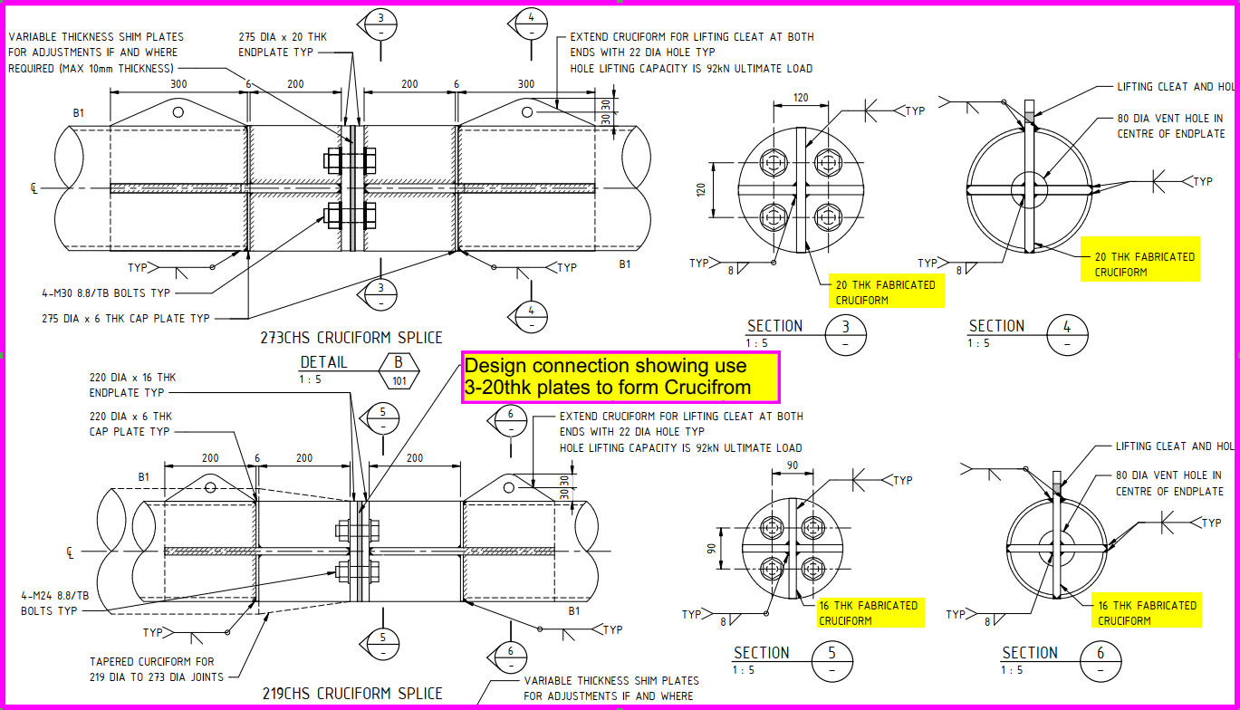
Another example involves the cruciform design connection, where the initial design called for three 20mm thick plates to be welded together to form the joint. This connection demands high accuracy in fabrication, as all plates must be perfectly aligned at 90º to avoid significant erection issues. During welding, there is a possibility of distortion, making it difficult to maintain the desired shape.
This is risky for the client – if they get it wrong they will lose: $abc and lose xyz months
The Solution
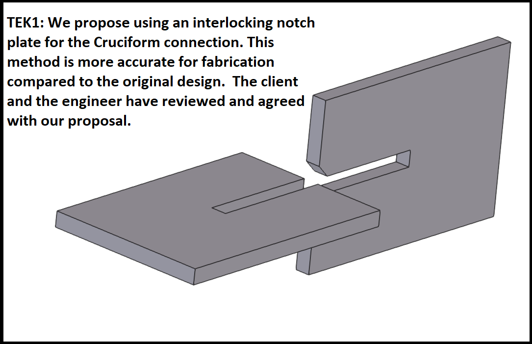
To address these challenges, TEK1 proposed a notched cruciform connection. Instead of three plates, we use only two plates, each with a notch. By interlocking the notched plates, we can avoid steel distortion and achieve the desired design shape more easily. This approach not only improves fabrication accuracy but also simplifies the assembly process.
Again our client was very pleased to see these cost-saving proposals coming from the steel detailer & we implemented this in our current model.
If you’re interested in having TEK1 manage your project, please send a quote request to our principal, Koshy, at koshy@tek1.com.au, and specify that you want Ramakrishnan to manage your project. We look forward to bringing our expertise to your next venture.
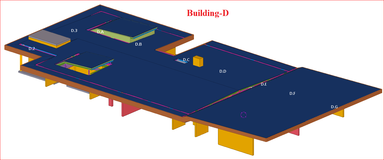
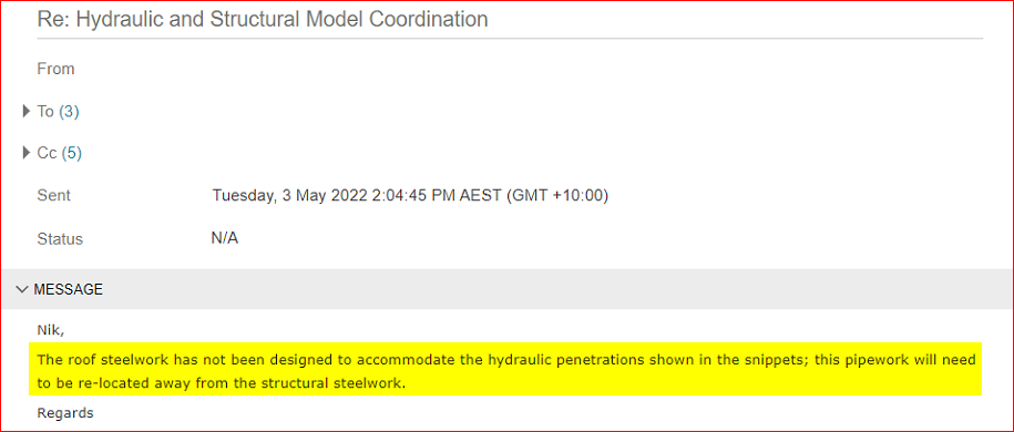
During the drafting phase of a recent commercial project, I encountered a critical issue involving clashes between downpipes and structural steel due to insufficient space for hydraulic piping routing.
Discovery and Verification:
Upon receiving architectural and structural drawings, I began modelled the structure and identified conflicts where downpipes from the gutters intersected with structural steel members.
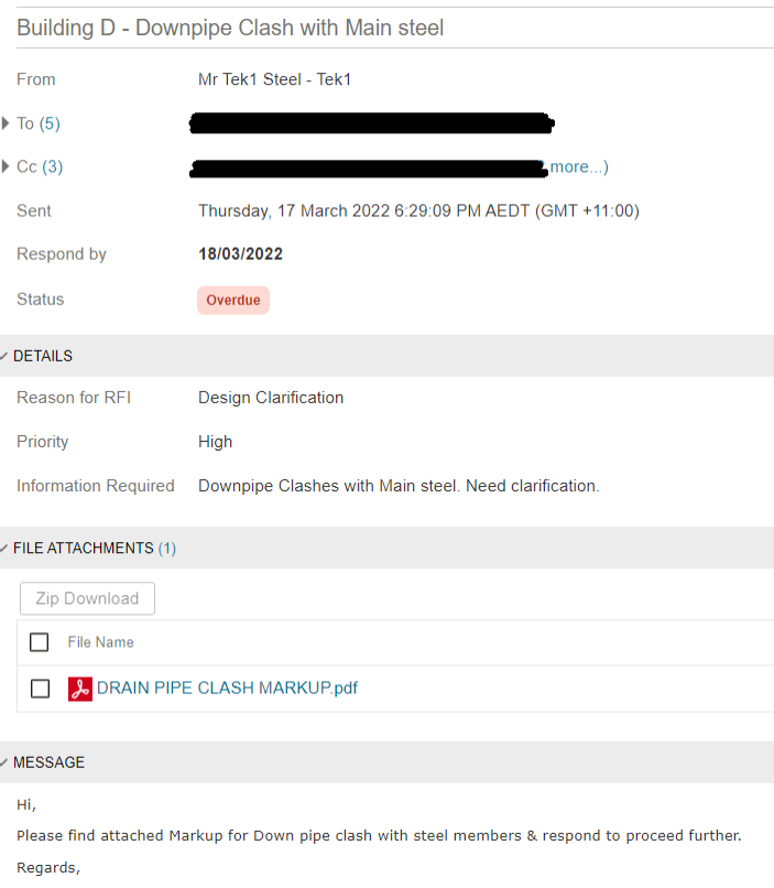
Initial attempts to accommodate the pipes exposed them below the ceiling, prompting me to request further hydraulic and IFC models for verification.
Upon submitting an RFI, the client confirmed that hydraulic piping routing had not been adequately considered in the initial designs.
This coordination oversight posed a significant risk to the project’s integrity.
Solution Implemented:
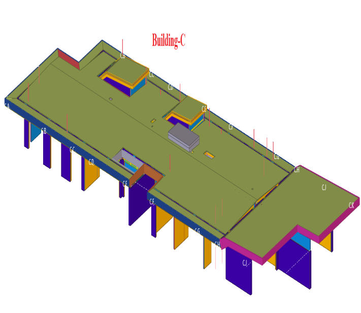
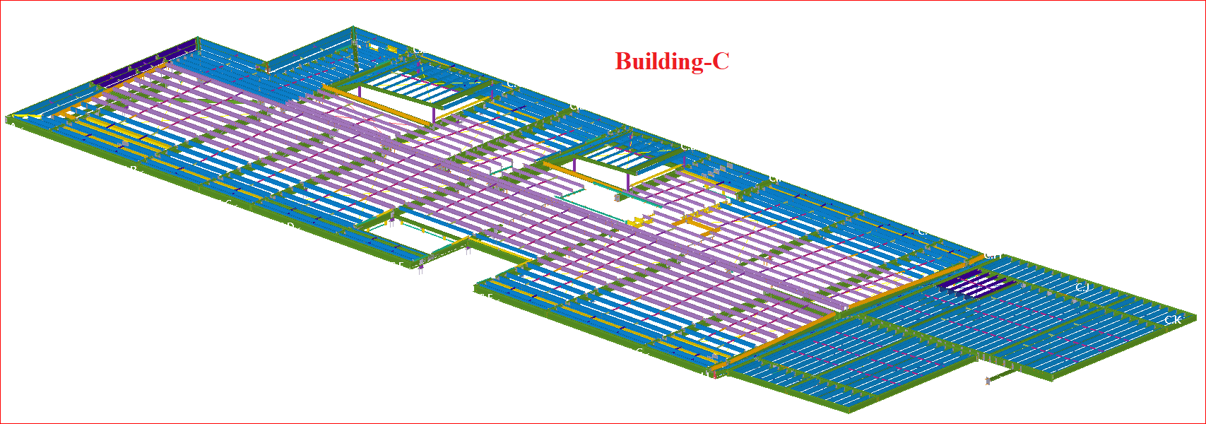
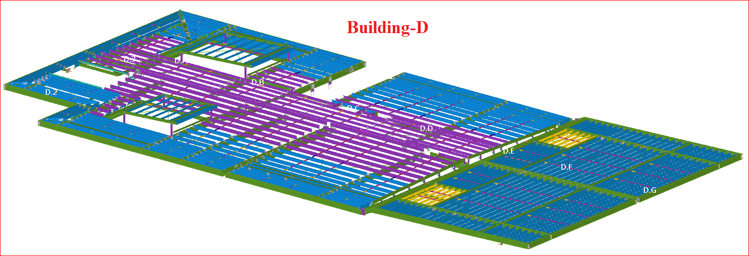
To address the issue without compromising building aesthetics, I proposed raising the roof by 300mm after consulting with the client, architect, structural engineer, and hydraulics engineer. This solution was agreed upon to prevent potential wastage (58 Tons for Each Buildings, which costs around $800000 for Main Steel alone. And if we include the Purlins, Erection and other inclusive charges on site, then it will be more than a million dollar loss for both the buildings) and ensure the project’s successful completion for both Buildings (Building-C & Building-D)
Conclusion:
We checked the design’s aspects in every possible way to make sure that there won’t be any loss by any means to our clients.