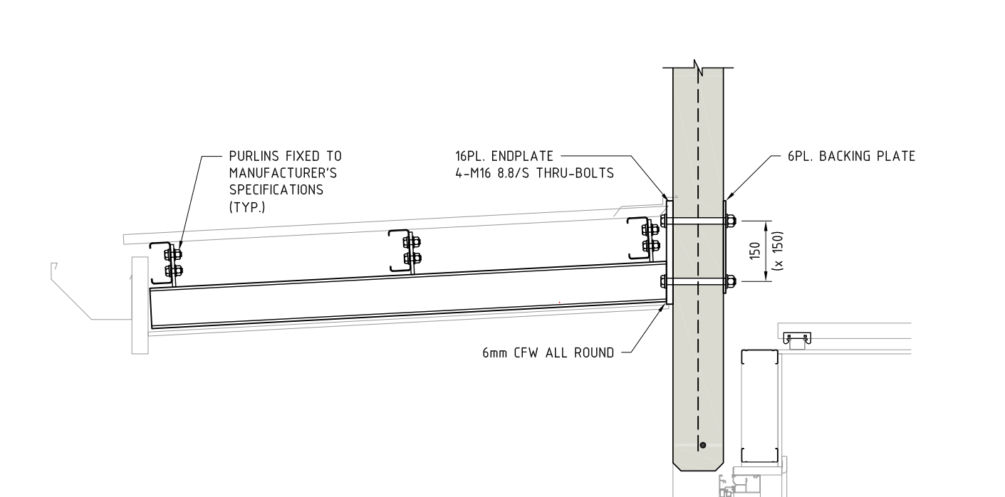
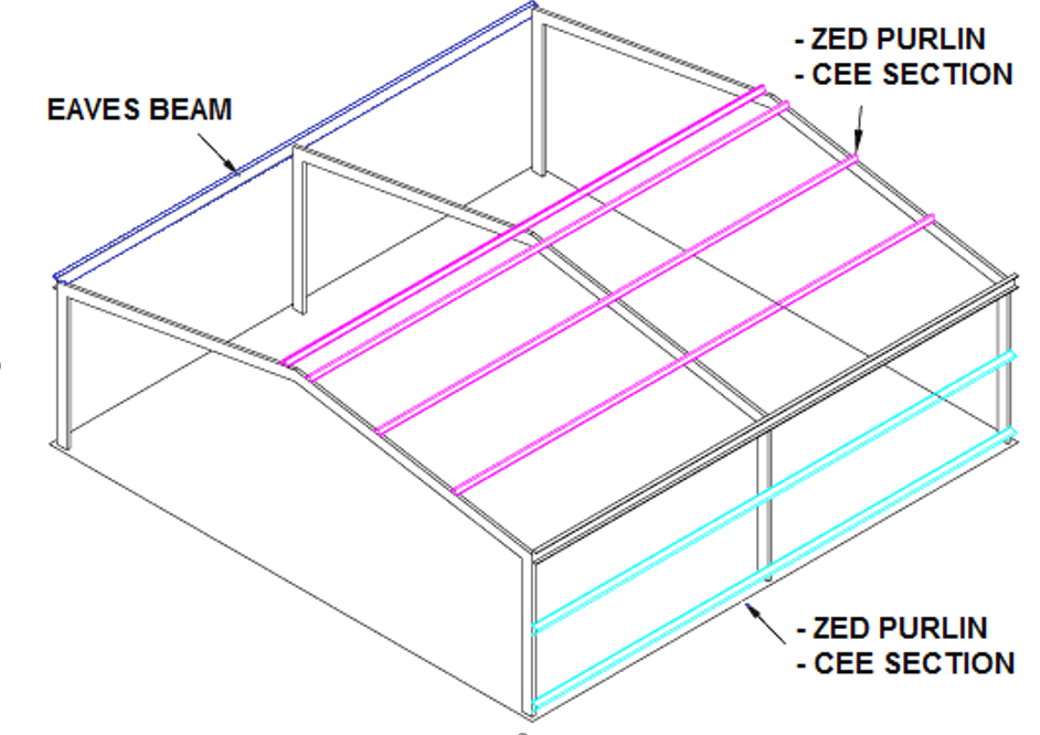
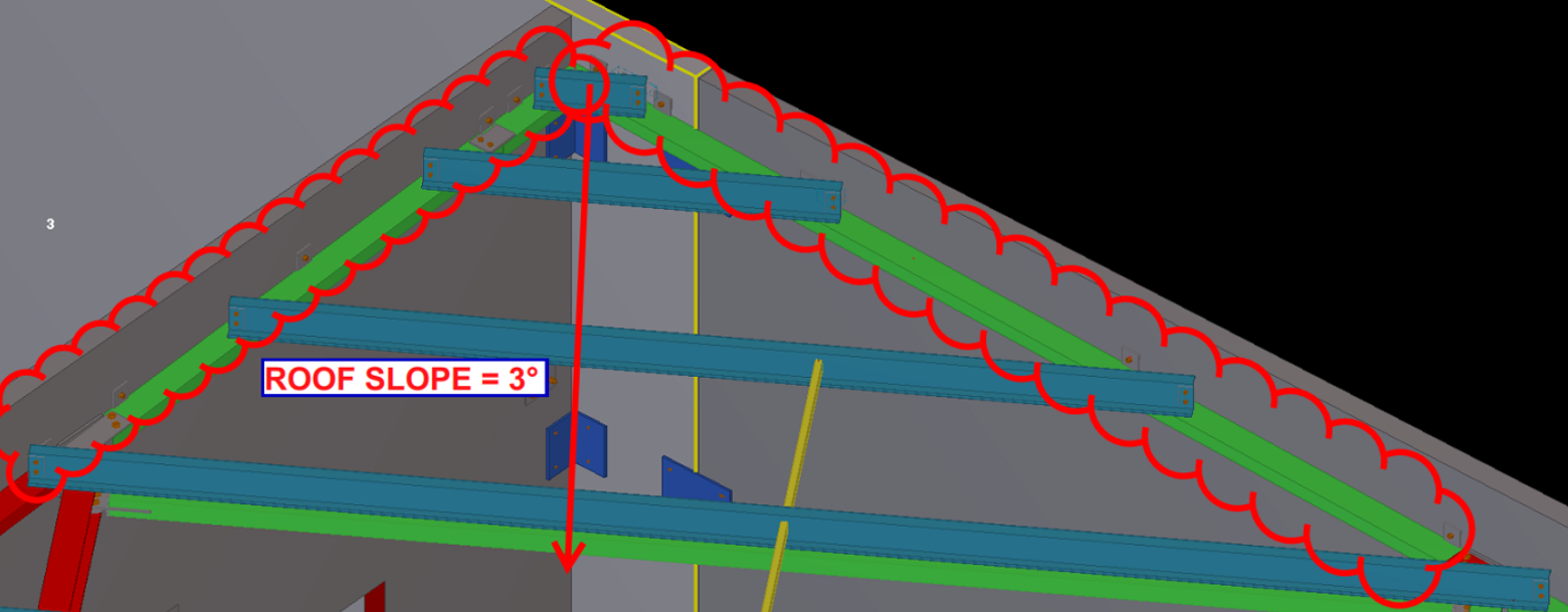
Consider the above drawing (Section View)? Have the purlins been placed correctly?
Have you ever considered a purlin’s orientation while detailing?
Pop-Quiz:
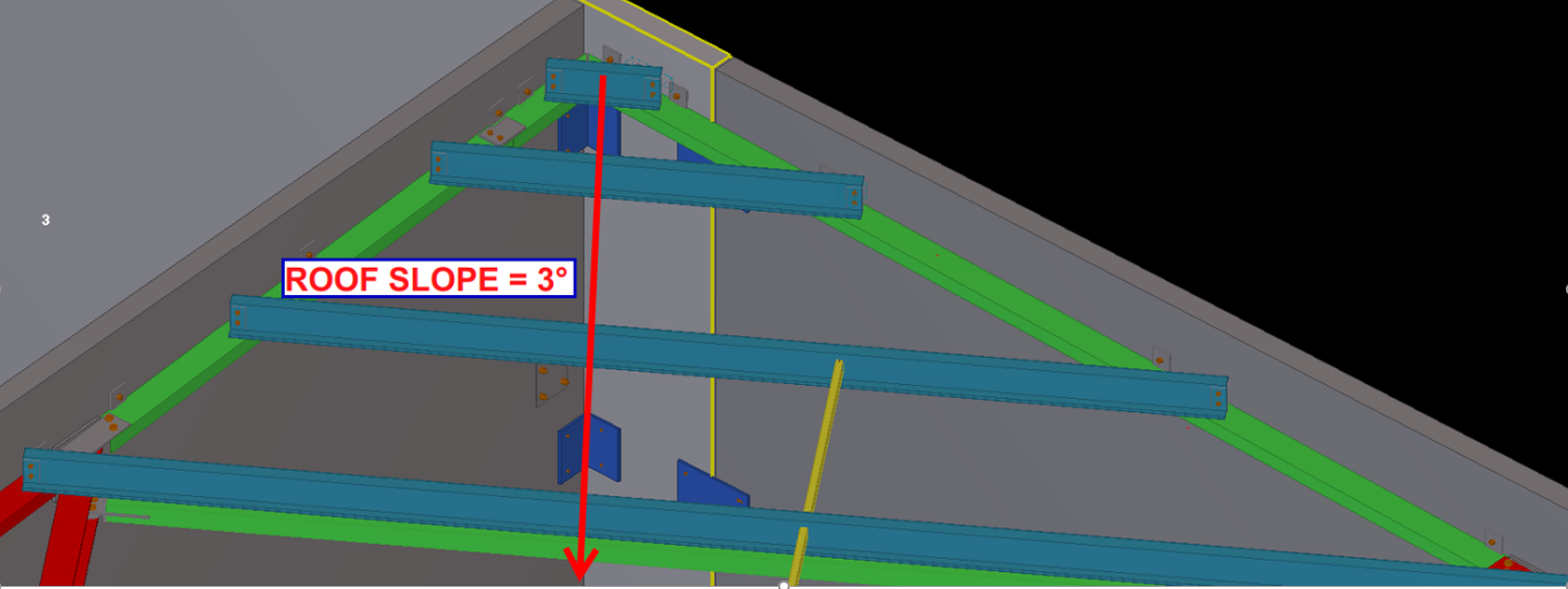
In the pic above, the structural engineer shows the purlin direction along the roof slope. Is this the correct way of orienting the purlin? i.e. Has the engineer made a mistake, and if so, why? (Answers below)
(Keep scrolling down…)
(Keep scrolling down…)
(Keep scrolling down…)
(Keep scrolling down…)
Answer:
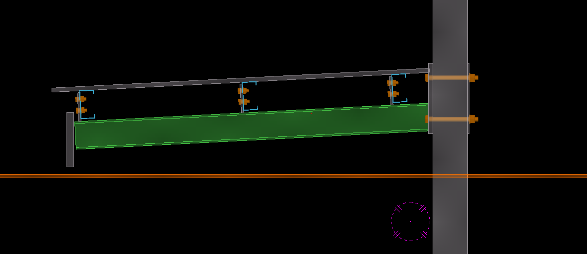
Definitely, this is an error on the structural drawing. Generally, detaliers have to consider a purlin’s orientation before placing it. Why? When the load applies on roof sheets , a twisting moment will occurs on the purlins. If we place the purlin direction along the roof slope then it will cause instability. So, the purlin direction should be always kept against the roof slope (as indicated in pic), even if the design indicates along the roof slope. Keep that in mind when you are detailing your next job. It’s a subtle but very important tip.
Notice how the purlins are oriented against the roof sheet?
To export Tekla drawings to PDF, various converter applications are available in the market. One of them is PDF creator by PDF forge. This is a free product and can be downloaded and installed directly to your system.
The following is the step by step procedure for pdf creator which can be used to set up your export files directly to a specific location.
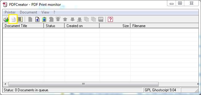
Open the application PDF creator (should be already installed onto the system).
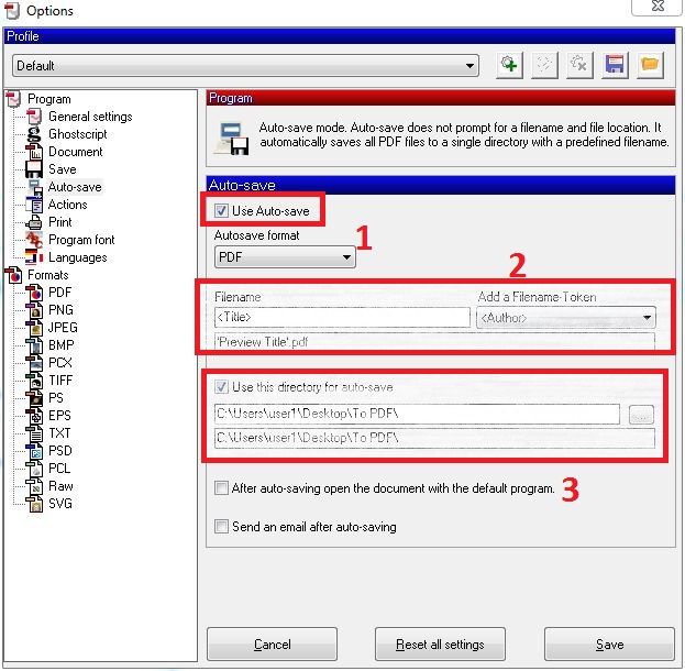
Select Options:
This is the UI. Selection Options (see what’s highlighted)
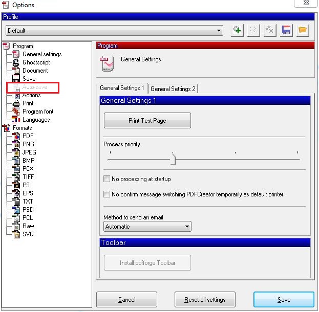
Now select and use Auto-save.
Select Autosave
Provide file name to <Title>. Provide the directory location where you require the pdf’s:
Save and close the Dialog box.
Now you can print to pdf using the PDF creator application.
You can download the free product from the following link: http://download.pdfforge.org/download/pdfcreator/PDFCreator-stable
(But be careful what you download: you do not want to get an internet transmitted disease by downloading from an irreputable source. Practice safe downloading: use anti-virus protection! Don’t hold me to account for that link).
BIM review is a desktlop software application by Strumis. It is similar to to Trimble’s Tekla BIMsight, having features such as: (i) clash checking capabilities, (ii) camera path viewpoints, and multiple format are supported including ifc xml step etc.
However we have to work to our clients requirements and at many instances they may not have access to Tekla BIMsight which is our standard protocol for model review. That can directly affect us.
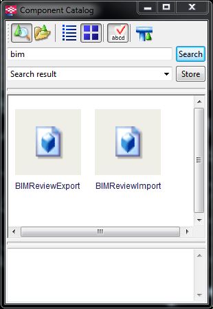
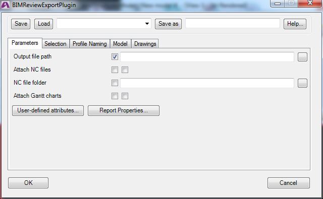
Thus an simple installation of the BIM review application and Tekla plugin for extraction of BIM review compatible files may be necessary.
The BIM review application is a free product and can be downloaded and installed directly with an active internet connection.
We continue our “Lessons learned” series. Can you spot the snake in the grass, in the following problem?
There are a million gotchas when detailing, which can trip up even the most experienced detailer. Here’s an issue that snagged us. Hopefully you can learn from our cock-up.
Showing building supports.
Generally, roof sheets are provided by the roof sheet erectors. But they want supports for the roof sheets from steel which given by steel detailers. Structural engineers will not give details for roof supports all the time. Sometimes they will miss it, or they will leave it to detailers. If that occurs, detailers must come with their own design (but, must get approval by struct engineers).
Showing the slope of the roof.
There are purlins in this picture to support the roof sheets. Detailers did their job as per structural documents. So that detailer’s work is finished. Pop quiz: the detailer’s work is finished, right?
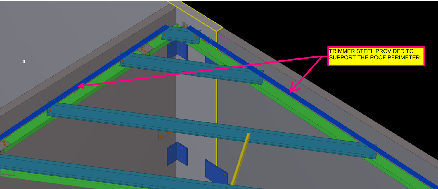
If you think like this, then you are wrong. Have a deep look into that: there are no supports for roof sheets around the perimeter of the roof.
The supports are missing, around the perimeter.
So at this situation detailers must check whether there is support for roof sheets at every ends. If there is any conflict found, you must need to provide steel for roof perimeter supports. Refer below images.
Here are the steels that are provided by our detailers. This can prevent site issues. Rectification on site is extremely costly, and worse, it’s extremely time consuming. You can avoid nasty delays by some carefully investigating the drawings, and avoiding dangerous pitfalls early on.
The supports are now drawn. Site issues are avoided.
As a detailer, we should constantly inspect and second guess the drawings and the details given to us by engineers and architects (well, mostly architects, because as a general rule, engineers are competent).
The Pop-Quiz
If you wish to engage in a pop-quiz: see the drawing attached here: Spigot Connection. What problems can you see arising if you follow the details put forward. The answers are contained below. Scroll down If you wish to see them.
Actually, the Steel post profile size is SHS 89*89*6 and the Steel stub profile size is SHS 75*75*6.
So we will get an overall 2mm allowance between Steel stub and post.
In this case we must consider the nature of the steel profile types.
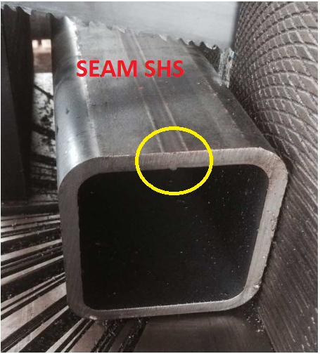
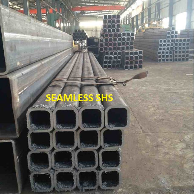
In the market we are have two different types of profiles, One is Seam SHS and another one is Seamless SHS.
See how there’s a notch here? Ok now we need a bit more clearance. This is because of the process by which this member was created. It starts of like a flat piece of metal, and is basically folded into a square. So the notch will be on the inside, where it is difficult to smooth off.Notice there is no notch inside? The clearance can be a little smaller in this case.
If we use Seamless SHS profile, then we can erect the members, Otherwise if the SHS are of the seam profile type then we can’t erect the member – there is not enough of a clearance.
Before carrying on the structural details we must discuss with Client/Fabricators and confirm which type of SHS they are going to use.
If they have Seam SHS only, then we must reduce the stub profile and make more clearance for the easy erection.
Written By Arokiaraj and his team; Our mistake in this regard was helpfully pointed out by Brett Kennard of Apollo Fabrication. Brilliant.
How to manufacture the T Bar is a question which frequently comes up.
The various options are
Make T-Bar from plates. (Involves welding plates together)
Cut from UB. (Might include wastage)
Buy Standard T-Bar. (May have its own constraints like minimum quantities)
Up until now we were detailing T bars as fabricated using T Plates. But now one of our clients has given a catalog from GALINTEL. Click on this link to go to their website.
Now whether a T bar should be option 1, 2 or 3 should a matter of preference of the fabricator irrespective of what is specified on the member schedule. Best course of actions is to RFI.
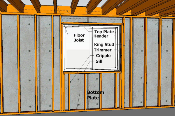
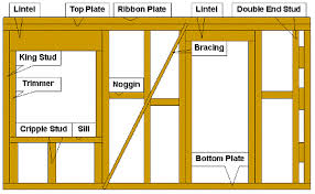
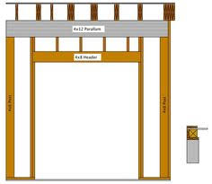
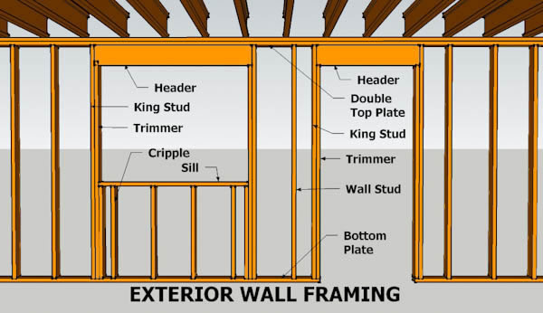
A single top plate can decrease lumber use and boost energy efficiency, but less lumber also decreases the bearing capacity of the top of the wall. … The tolerance requirements ensure adequate bearing capacity by directing the loads from the framing above the top plate directly into the studs below.
A Top Plate is the continuous timber beam on top of the walls that supports the roof structure by carrying the vertical forces from the rafters to the wall studs.
“A prudent person foresees danger and takes precautions. The simpleton goes blindly on and suffers the consequences.” –Ancient Proverb
We might do an entire series on these types of projects. Here is one such example:
We’ve seen some unique designs from architects who were either:
smoking crack cocaine, or were
fresh grads straight out of uni, or
who were many years experienced in the trade of being incompetent. Here is another night mare story which will either make you chuckle or shake your head and weep:
A Bridge That Cannot Be Fabricated: Avoid it!
A fabricator walks in wanting to fabricate a bridge. It’s a government project. So the tax payer is paying for all of this. The tax payer’s expert – who ever that may be – has no clue what they’re doing so they approve the designs and planning for a pedestrian bridge – which should be a really simple and straight forward project – to the total cost of $5 m to the tax payer. But of course, the architect and his bureaucrat don’t want to make a simple, ordinary bridge — oh no, that will not do. They want to make a name for themselves. So they design a bridge that simply cannot be fabricated. I wish I could show you the drawings, and explain in detail why it cannot work, but the bottom line is that, using the current technology we have, and that which is available in the best workshops in the land – I cannot see how this thing can be made. Maybe some day when we get some alien technology from Klingon, making this bridge will be a piece of cake. But till that time, mere human beings might struggle.
Think of taking a beam, twisting it at both ends (like you would do to a piece of string), and then trying to rotate it into the shape of a double helix. Do this for 6 beams and try and connect them together – like the spokes of a wheel being connected to a hub, some 10 m away. It’s not going to work! I call up my fabricator and tell him my concerns, warning him, in fact, of the dangers of this project, with a simple question: “How are you doing to fabricate this thing?”
His response: he insisted that it could be done. I insisted it could not – that he should try doing it before jumping into a dangerous and foolhardy project which he would be blamed for, and which he probably was not going to get paid for.
In any case it was clear to me that this was a building and construction project that was going to be very badly managed, and incur huge costs to the tax payer. The bridge that would be built, would be different to that which was originally designed. This means potentially huge rectification costs, from all parties concerned. You could easily treble the cost of the bridge, and double the deadline, and you still wouldn’t be half way there. In the end, the tax payer would be taken for a ride.
I said my piece, and in the end, I declined to be involved in the project.
Perhaps in time, maybe over the next 15 years, I can update you on the status of the project and the costs incurred to the tax payer.
Morale of the Story:
Listen to good advice, especially when it’s given for free.
Stay away from dangerous projects, and you won’t fall into a pit.
Don’t let a government bureaucrat anywhere near your projects – they’re always spending someone else’s money and not their own, so fundamentally: they don’t care.