When the model is amended after issuing the first set of drawings, the affected assembly drawings will appear as “Parts Modified” after numbering is completed. While updating such drawings, certain considerations are important to ensure effective and quick detailing.
1. Freeze Option
When Freeze is OFF, Tekla automatically updates dimensions according to the movement of parts. While this may seem convenient, the decision to turn Freeze ON or OFF depends on the nature of the amendment.
- If no new members are added to the assembly and only existing parts are moved, it is recommended to keep Freeze OFF, as Tekla will correctly update the dimensions.
- If new parts are added to the assembly and Freeze is turned OFF, Tekla will automatically generate additional dimensions for the new members and may also alter existing dimensions. This can result in extra work to restore the original dimensioning arrangement.
Guideline:
- When no new parts are added, turn Freeze OFF.
- When new parts are added, turn Freeze ON.
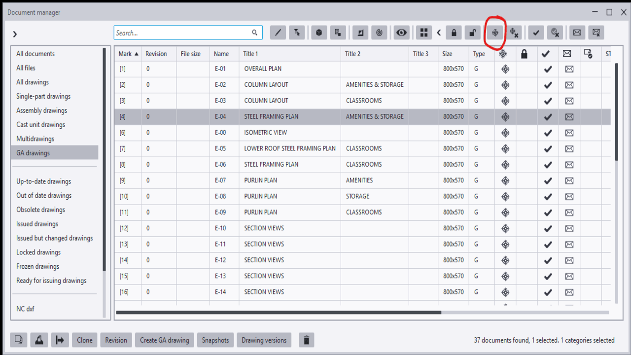
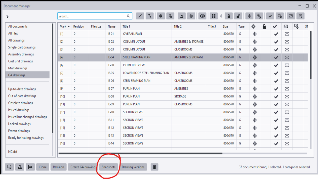
2. Snapshot Option
Among the drawings marked as “Parts Modified,” not all drawings necessarily contain actual changes. Some assembly drawings may appear as modified because they share common connection components with other assemblies that were amended.
In such cases, the drawing may not have any visible changes and may only require an open-and-close action. However, there is a risk that certain dimensions may be automatically deleted or altered by Tekla during the update.
To avoid missing dimensions or unintended changes, the Snapshot option is highly useful. It allows detailers to compare the drawing before and after the update. By reviewing the differences, any unnecessary or unintended modifications can be identified and corrected, thereby minimizing the risk of errors.