Tekl1 modelers typically create and develop Tekla models close to the model origin (0,0,0) to maintain optimal modelling performance and accuracy. However, when sharing IFC files for coordination, clash detection, or BIM integration, the model may need to be positioned at its actual project location using global Easting and Northing coordinates.
By exporting the model using a Base Point, multiple IFC models from different consultants and contractors can be accurately overlaid within BIM coordination software.
Setting Up a Base Point
To export a Tekla model to global coordinates:
Open File > Project Properties > Base Points.
Create or modify a Base Point.
Enter the required Easting and Northing coordinate values.
Use the Base Point when exporting the IFC model.
When the IFC is exported using this Base Point, the model origin is shifted to the specified Easting and Northing coordinates, allowing the model to be correctly positioned within the global coordinate system.
Using a Specific Model Point as the Base Point
In addition to using the model origin, Tekla allows any point within the model to be selected as the Base Point.
This provides greater flexibility when project coordinates are referenced from a specific grid intersection, column location, survey point, or benchmark. The selected point can then be assigned the required Easting and Northing coordinates during export.
Applying Rotation
The Base Point functionality also allows the model to be rotated relative to the selected reference point. This is particularly useful when the project grid is not aligned with true north or when a specific orientation is required by the client or project team.
By defining both the coordinate location and rotation, the exported IFC can accurately represent the model’s real-world position and orientation.
Demonstration
The video below demonstrates the complete procedure with a practical example, showing how to:
Split Large complitcated assemblies into sub assemblies.
Preferably do that in the modeling stage. But if you have already modelled and do not want to change, split groups of parts into virtual sub assemblies for detailing purposes.
Detail the the sub assemblies. That will reduce clutter in the main view of the drawng.
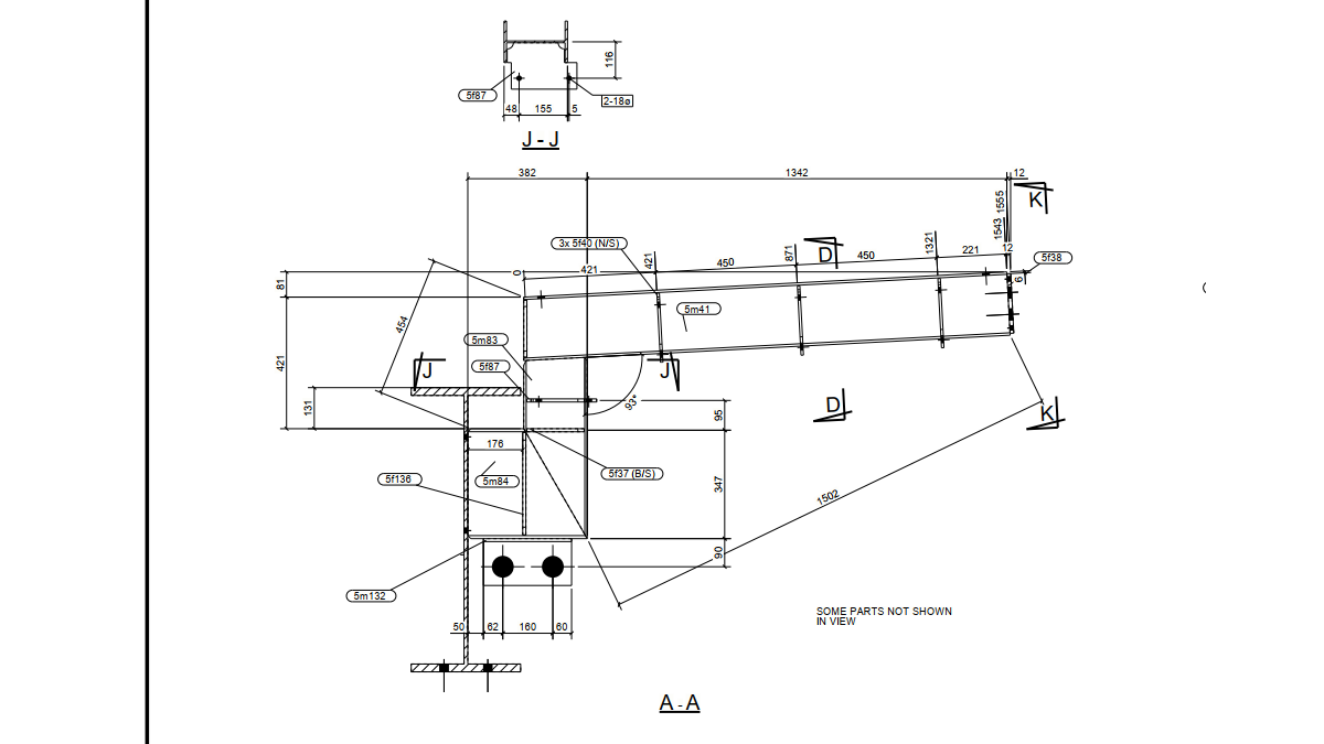
Single Part Views
Parts are cut to single part drawings, palletted and given to the boiler maker with Assembly drawing. Part drawings will be missing.
But the boiler maker will need know some dimension in the parts to assemble the weldment correctly.
Hence you may have to produce single part drawings within the assembly drawing.
This will reduce clutter and make life easy for you as well as for the boiler maker. Make sure necessary single part drawings are added in the assy drg
Detail Views
In a cluttered drawing, main views will have many parts shown which basically makes those views very difficult to use.
You add detail views and hide parts for clarity.
Short Cuts
You must have Show / Hide parts in drawing short cuts. Else you will spend a lot of time showing and hiding with right click
In this blog, we will look at how to create and share new materials in a Tekla model. By default, Tekla comes with a predefined list of materials stored in the system drive (C drive). However, in many projects, we often need to add custom materials based on project requirements. To add a new material, go to the Menu at the top left corner, navigate to Catalogs, and then open the Material Catalog. From there, select an existing material, right click & selct “Add Grade,” rename it as required, and assign the appropriate density. Once saved, the new material will be available in the model.
When sharing the model, especially using the db1 file to reduce file size, the newly added materials may not be available to the recipient. This is because custom materials are stored separately. To ensure the other user can access the same materials, you need to share the file named “matdb.bin” from the model folder. This file is created only when new materials are added and must be included along with the db1 file.
Alternatively, there is another method to share materials. In the Material Catalog, you can use the “Export” option available at the bottom to save the material data as a separate file. This file can then be shared, and the recipient can import it into their Material Catalog to access the same materials.
Watch the video below for a step-by-step demonstration of this process.
must be installed and enabledWrong $CFG->dbtype. You need to change it in your config.php file from ‘mysqli’ to ‘mariadb’
site not https
if this test fails, it indicates a potential problemIt has been detected that your site is not secured using HTTPS. It is strongly recommended to migrate your site to HTTPS for increased security and improved integration with other systems.
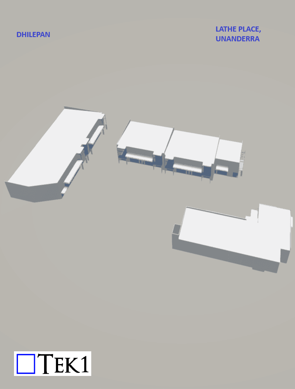
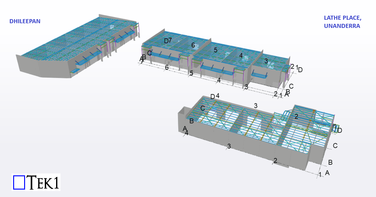
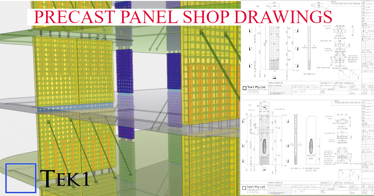
At Tek1, we specialize in transforming complex architectural visions into constructible shop drawings. This model snapshot showcases a recent precast project where aesthetic texture meets structural integrity.
Technical Highlights:
Software: Modeled 100% in Tekla Structures for BIM-ready accuracy.
Surface Treatment: Seamless integration of Reckli formliner patterns, ensuring the architectural finish aligns perfectly across panel joints.
Detailing Depth: Full reinforcement modeling (rebar and mesh), including lifting anchors, grout tubes, and connection hardware.
Manufacturer Ready: Our shop drawings are designed to minimize onsite clashes and streamline the casting process at the precast yard.