TEK1 completed a Pergola project for a prominent organization in Australia. The goal was to provide detailed support steelwork for Pergolas.
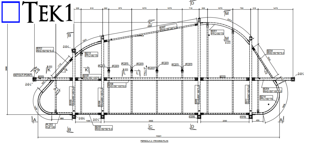
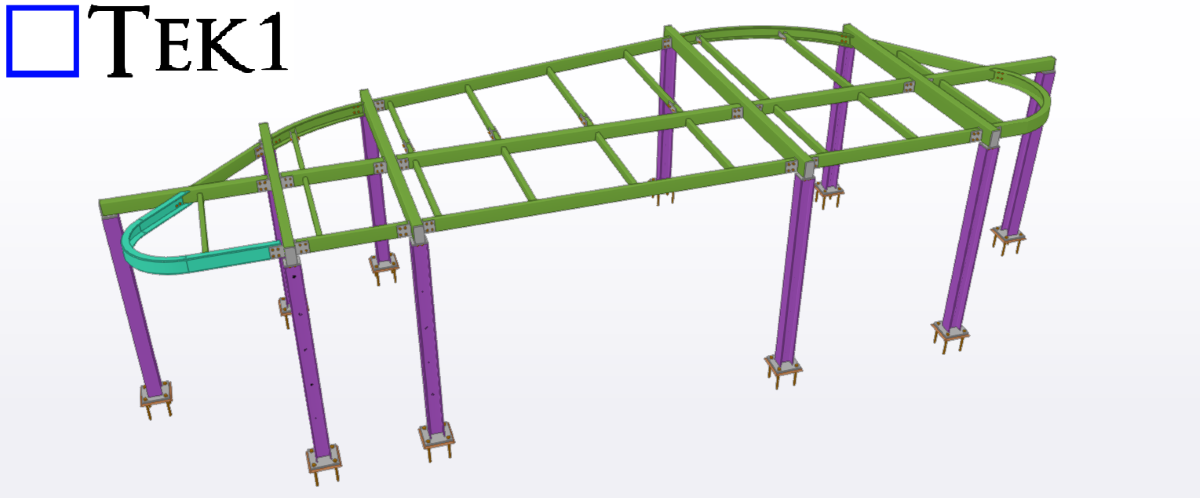
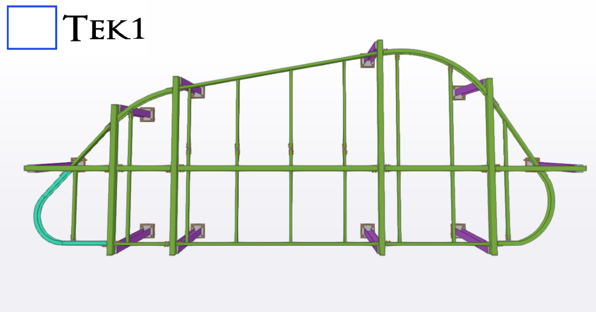
TEK1 completed a Pergola project for a prominent organization in Australia. The goal was to provide detailed support steelwork for Pergolas.
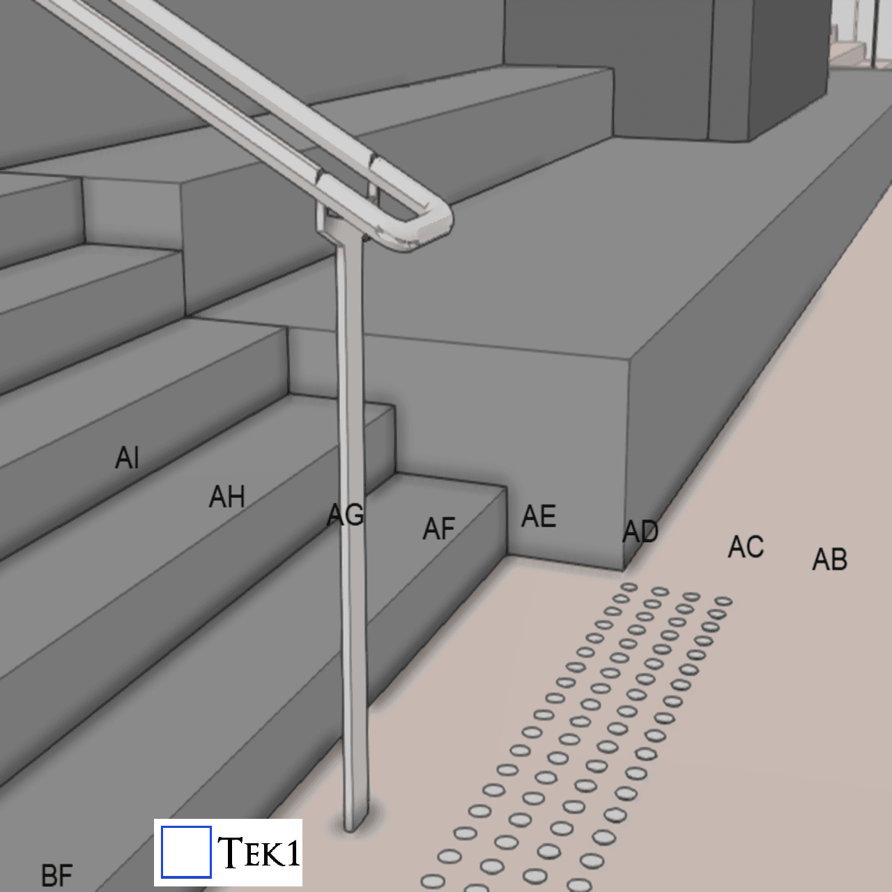
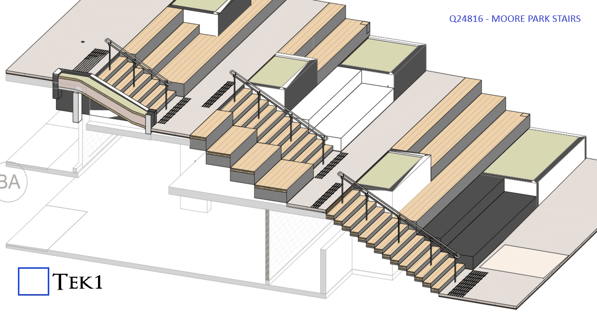
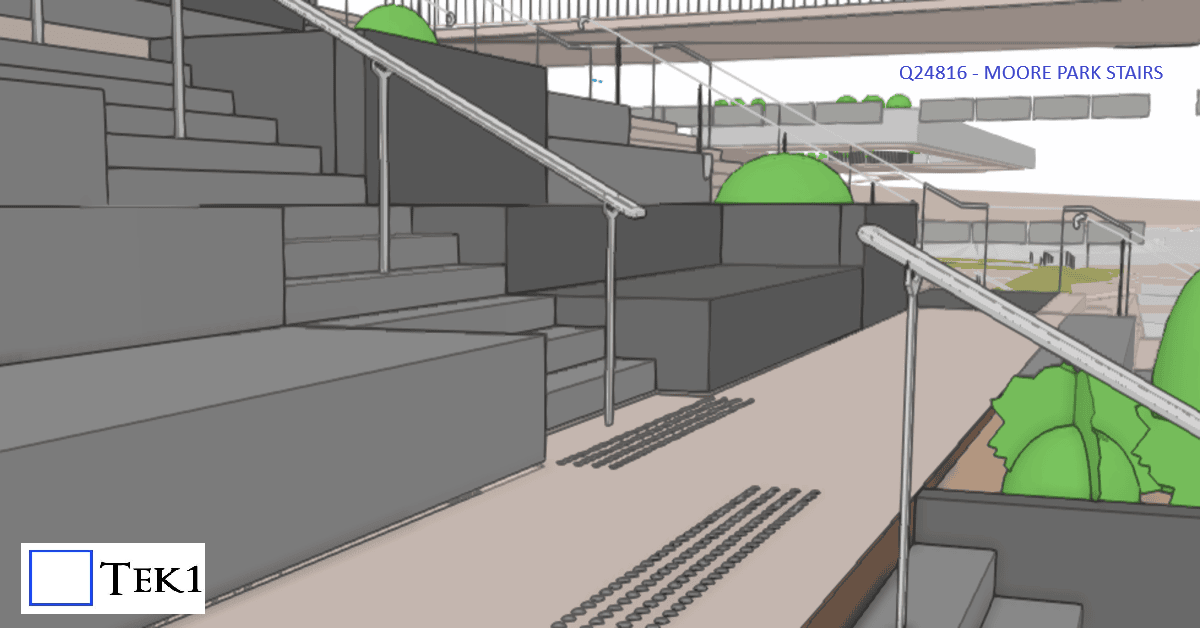
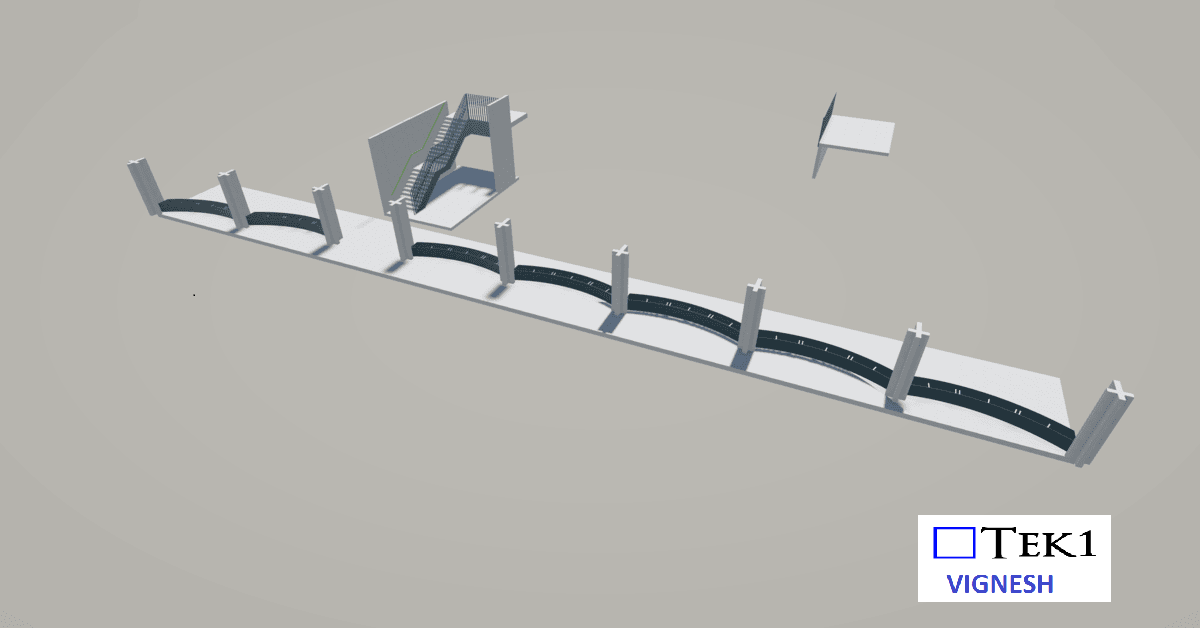
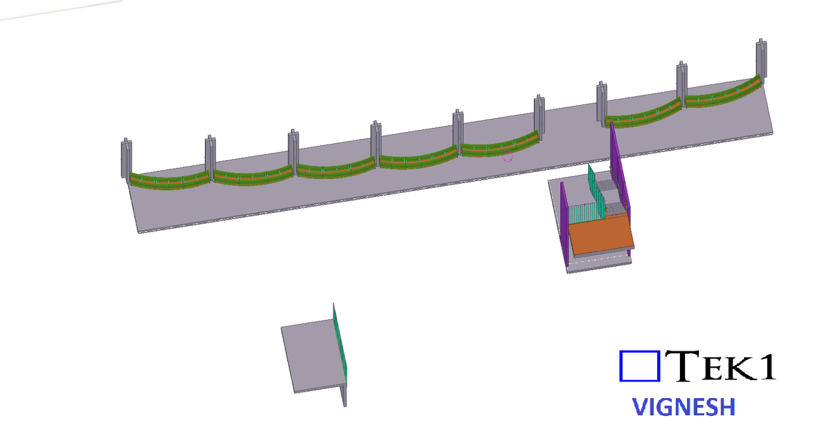
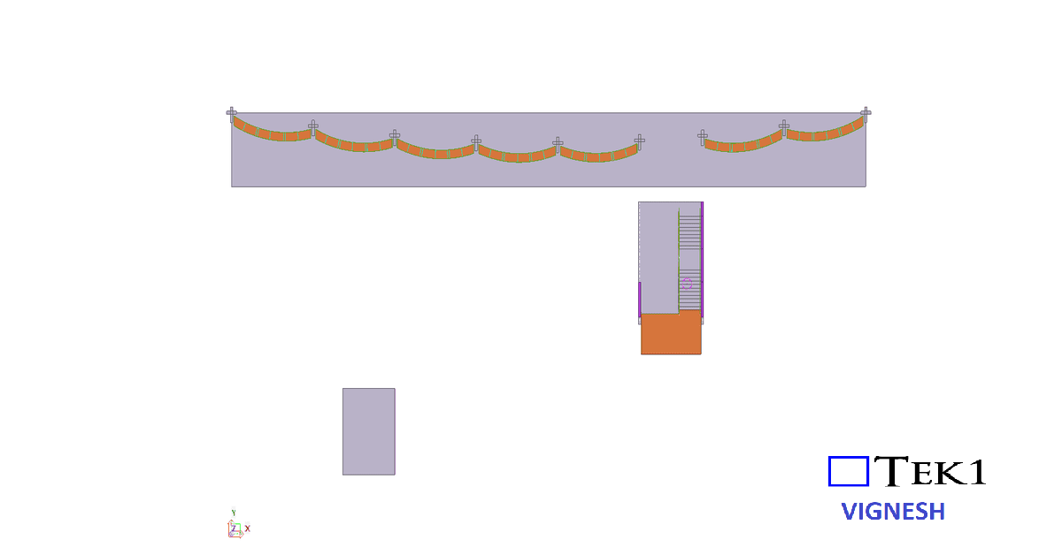
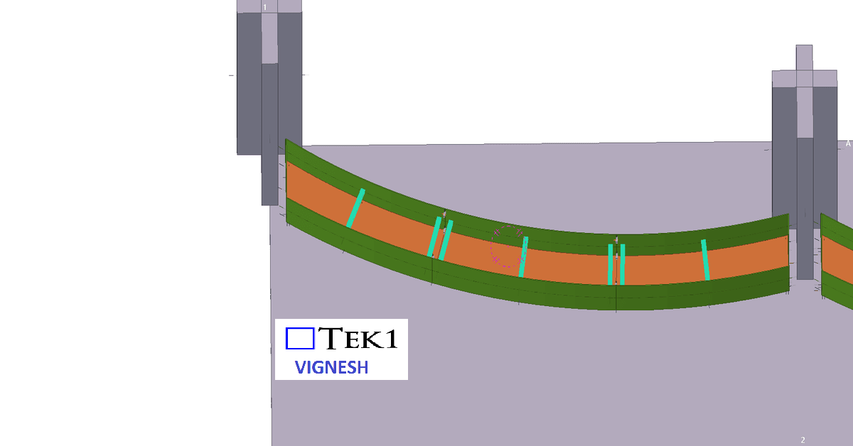
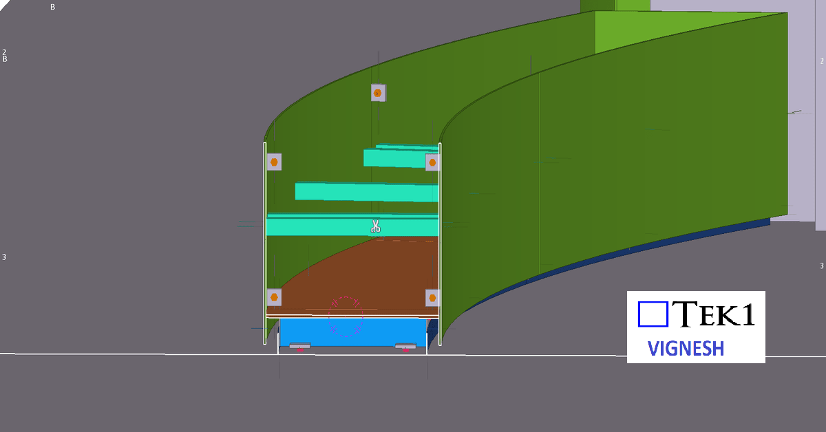
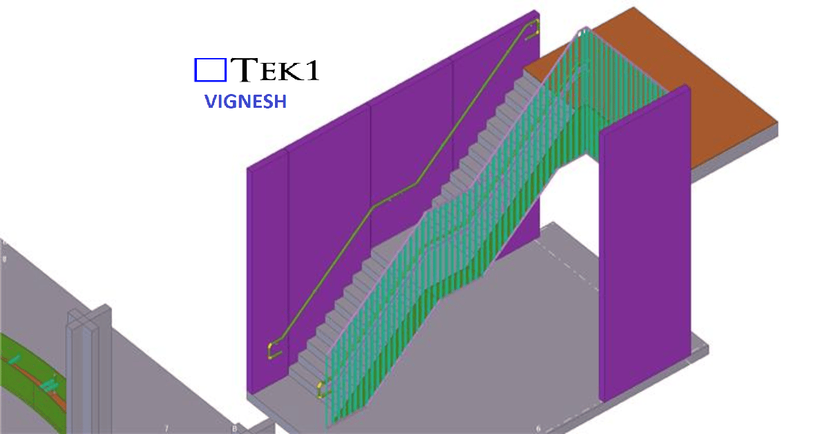
At Moore park, there are several stairs & ramps. Among them is a stair which connects walkways at different levels. The direction of the stairs is perpendicular to the direction of the walkways.
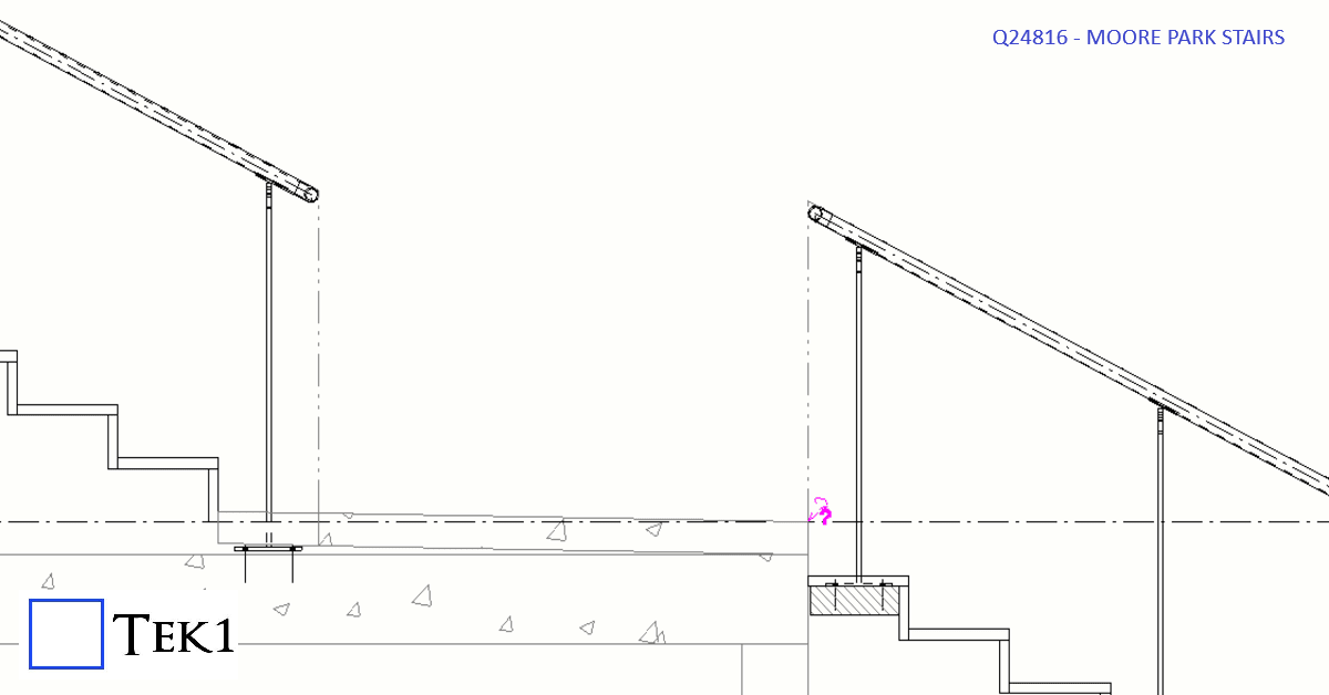
According to the sandards, handrails at stairs must extend beyond the stair flight to improve accessibility and safety. The standard requires:
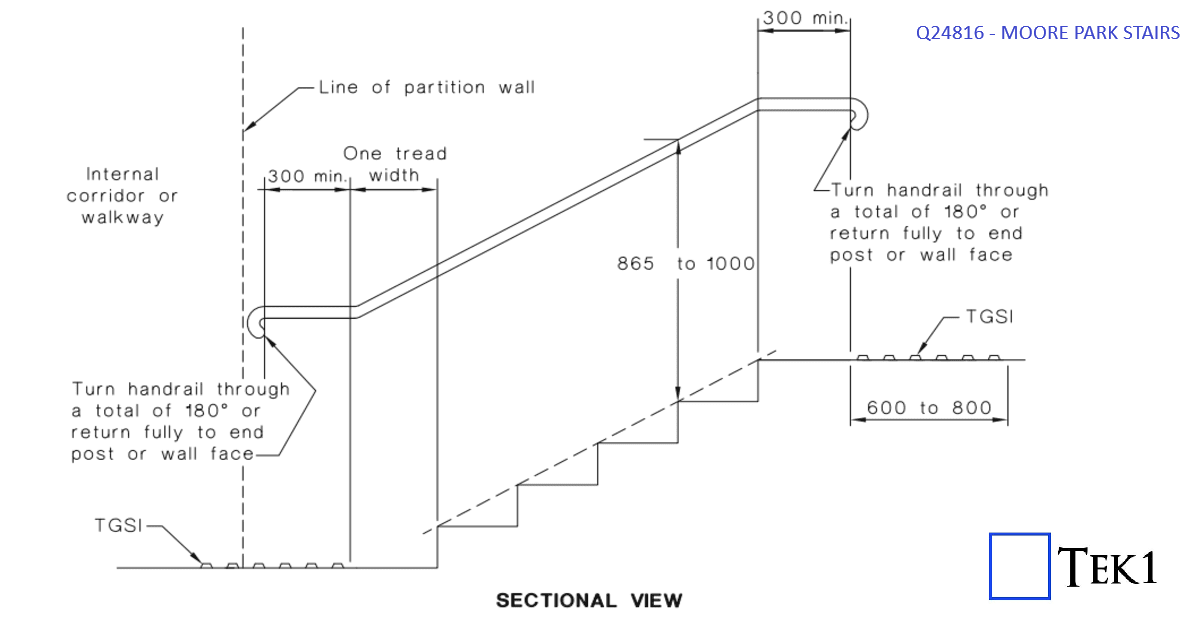
However, extending the handrail rail would protrude in the walkway & could cause collision hazard or reduce the effective width of the walkway.
To avoid this, the handrail extension was omitted. The architect has marked this as performance solution & this is one of the few cases where this 300mm extension does not apply.
We are proud to be a part of the team in Marymede Planter box project.
Our detailing team worked closely with architects to ensure tolerances and offsets were met without compromising design intent With a limited fabrication and erection window, our detailing team adopted a fast-track workflow using Tekla Structures for 3D modeling.
This allowed us to provide early shop drawings for procurement and parallel review of sections still under coordination.
You may email us when the app is getting ready for instant shop drawings at info@tek1.com.au
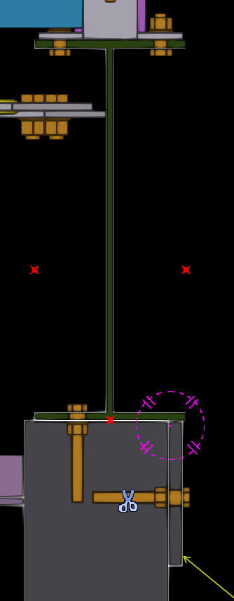
In this blog, I’d like to share an issue we faced while detailing Platform Screen Door (PSD) support beams in a metro station project.
Our scope was to provide structural beams to support the platform screen doors. The design also required stiffeners in these beams for structural strength.
The Issue We Identified
Before placing the stiffeners as per the design, we reviewed how the door frames would connect to the beams. During this check, we realized that the stiffeners could clash with the door frame supports.
As expected, when we reviewed the door frame support details, the clash became clear.
We raised this issue with the relevant team, and they advised us to modify the stiffener size so it would not interfere with the door frame supports.
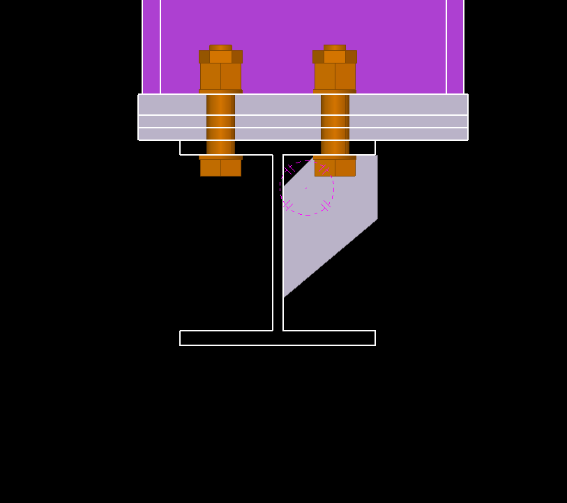
As detailers, we shouldn’t just place elements exactly as shown in the design. We must also think about how other components will connect and function.
This is especially important when our steel supports secondary steel, equipment, or framing systems. A little extra attention during detailing can prevent major issues during installation.
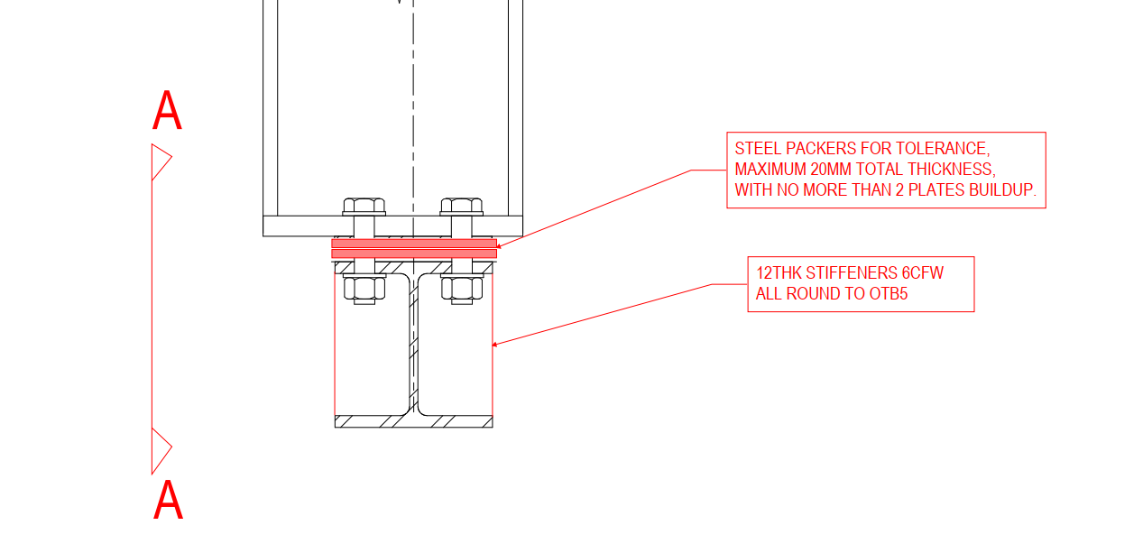
Detailers must exercise caution when working with bolts and edge distances, as these are common areas for errors in structural detailing. In this blog, I’ll share my experience with a bolt edge distance issue and how it was resolved.
The Scenario
In a recent project, the design required a UB (Universal Beam) to sit on a 200mm-thick concrete wall, secured with M20 chemset bolts.
Upon review, it became clear this setup wasn’t feasible:
Additionally, the beam wasn’t centered on the wall, further complicating the bolt placement.
The Proposed Solution
To address the issue, I proposed welding plates to the bottom of the beam. This adjustment allowed the beam to be bolted to the side of the wall rather than its top.
The Engineer’s Feedback
After reviewing the proposal, the engineer suggested a simpler solution: using a single row of bolts instead of two. This change eliminated the edge distance problem.Engineer mentioned that one row of bolt is enough for this beam.
In this project, the engineer did not accept our proposal, as they determined that the beam does not require that level of support. However, as detailers, it is our responsibility to highlight the issue and propose suitable solutions.
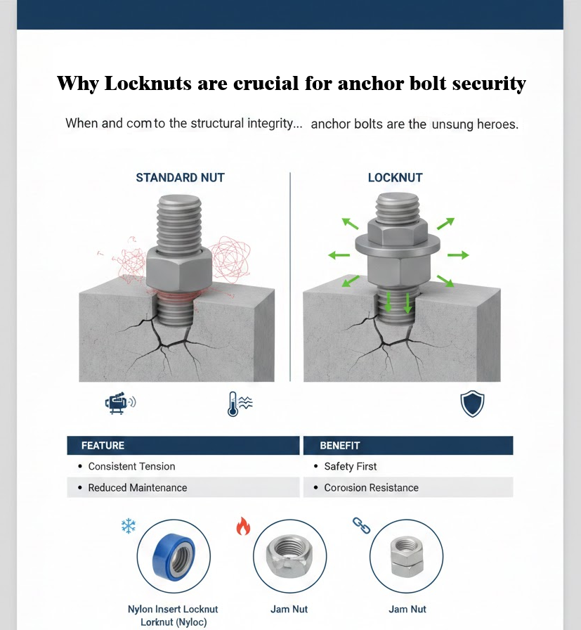
Anchor bolts are the literal foundation of structural stability. They secure steel columns, heavy machinery, and critical structural components to concrete foundations, resisting uplift, shear, and dynamic forces.
But even the strongest anchor bolt is only as reliable as its ability to stay tight.
In industrial environments where vibration, movement, and thermal cycling are constant, relying on a standard nut alone is often not enough. This is where locknuts become a non-negotiable component of anchor bolt assemblies.
When we think about structural failures, we often imagine snapped steel or crumbling concrete. However, one of the most common—and preventable—failure points is vibration-induced loosening. Enter the locknut – the small but mighty component that ensures your anchor bolts stay steadfast.
Standard nuts rely on the friction between the bolt threads and the nut threads, maintained by the tension (clamp load) of the bolt. However, two main factors can compromise this:
Thermal Expansion: Fluctuating temperatures cause the bolt and the fixture to expand and contract, periodically reducing the clamp load.
Vibration: Constant motion from machinery or wind loads can cause minute “slips” in the threads.
A locknut is a specialized fastening device designed to resist loosening when subjected to vibration and torque. Unlike standard nuts, which rely solely on friction created by initial tension, locknuts incorporate various mechanisms to maintain their grip, even when external forces try to reduce that tension.
Don’t let a $2.00 part jeopardize a $200,000 project. Using high-quality locknuts on your anchor bolts ensures longevity, reduces maintenance costs, and—most importantly—guarantees structural safety.

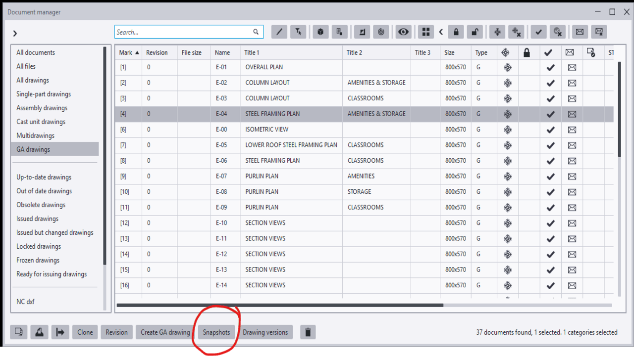
When the model is amended after issuing the first set of drawings, the affected assembly drawings will appear as “Parts Modified” after numbering is completed. While updating such drawings, certain considerations are important to ensure effective and quick detailing.
When Freeze is OFF, Tekla automatically updates dimensions according to the movement of parts. While this may seem convenient, the decision to turn Freeze ON or OFF depends on the nature of the amendment.
Guideline:
Among the drawings marked as “Parts Modified,” not all drawings necessarily contain actual changes. Some assembly drawings may appear as modified because they share common connection components with other assemblies that were amended.
In such cases, the drawing may not have any visible changes and may only require an open-and-close action. However, there is a risk that certain dimensions may be automatically deleted or altered by Tekla during the update.
To avoid missing dimensions or unintended changes, the Snapshot option is highly useful. It allows detailers to compare the drawing before and after the update. By reviewing the differences, any unnecessary or unintended modifications can be identified and corrected, thereby minimizing the risk of errors.
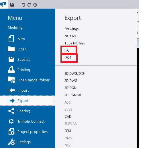
When we export models from TEKLA Structures, we mainly see two options:
Both formats serve the same purpose—model interoperability—but they work differently, support different levels of data, and offer different quality of geometry.
In this blog, we explore the key differences, benefits, and when to use each format.
This is the old IFC format used by most companies for many years.
✔ General coordination
✔ Clients who request IFC2x3
✔ Old software compatibility
This is the newer and more advanced format.
✔ Modern BIM tools
✔ Better visual quality
✔ Detailed model sharing
| Feature | IFC2x3 (Export IFC) | IFC4 |
|---|---|---|
| Geometry | Basic (Rough) | Smooth & Accurate |
| Curved Shapes | Approximate | Perfect & Precise |
| File Size | Larger | Smaller |
| Compatibility | Very High | Medium |
| Details | Limited | More Detailed |
| convert IFC object to Steel Member | Work well | Can’t convert |
If your client or BIM Execution Plan (BEP) does not specify the format, use IFC4 for best geometry