We hope you found our previous blogs on the Sydney Metro project insightful. If you missed them, check them out.
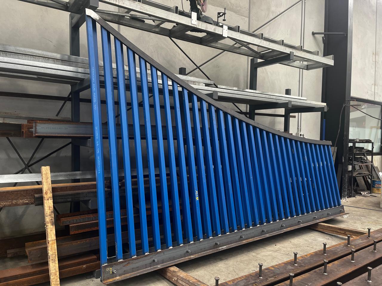
In this blog, I’d like to share another connection detail we proposed to the structural engineer on the Sydney Metro project
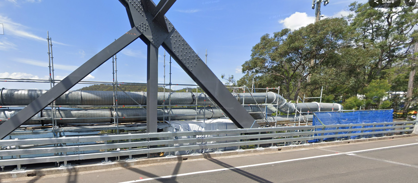
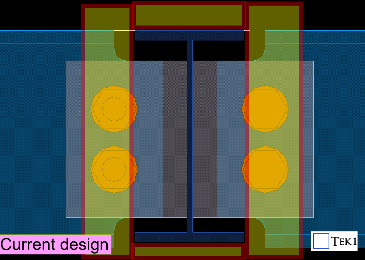
Since this is a metro project, fireproofing sheets are required on steel members as per the structural engineer’s specifications. However, the original connection details provided by the engineer were not feasible interms of installation of fireproofing sheets — they would make installing the fireproofing sheets difficult and time-consuming.
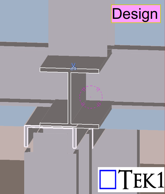
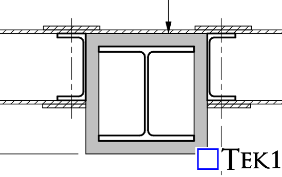
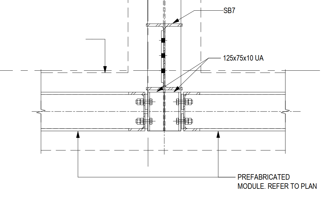
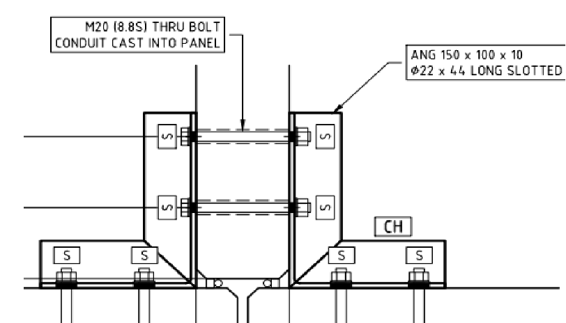
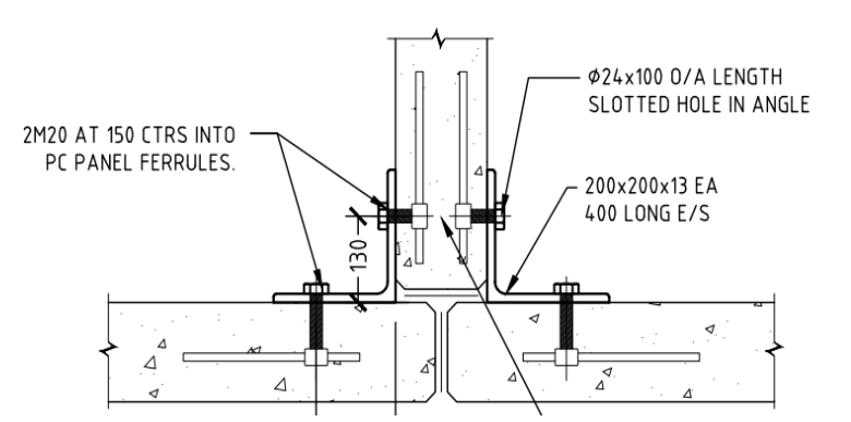
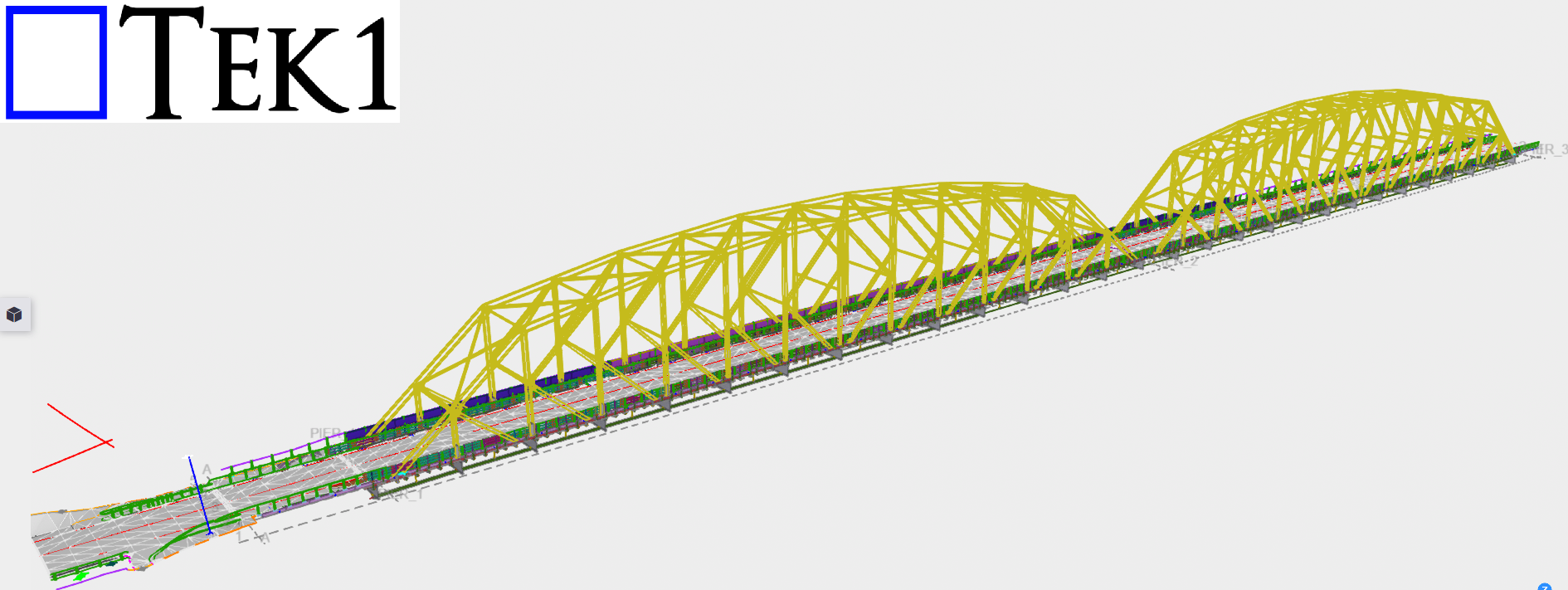
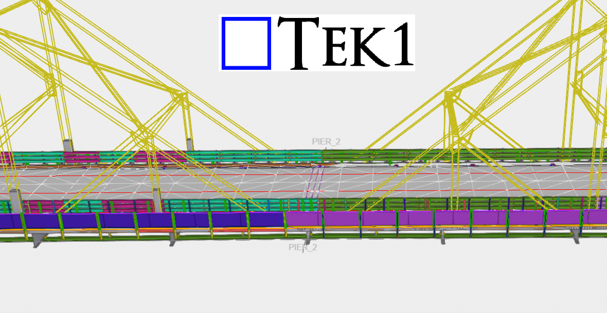
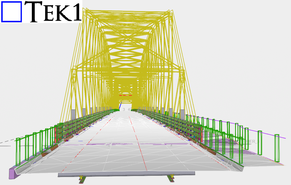
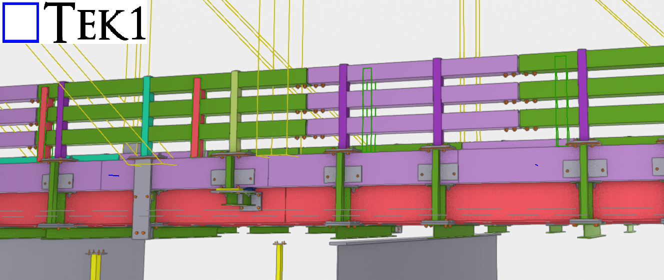
Please see the connection details below. These are the standard connection details typically used for the steel members.
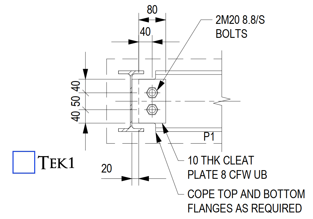
However, applying these as-is may create difficulties during the installation of the fireproofing sheets.
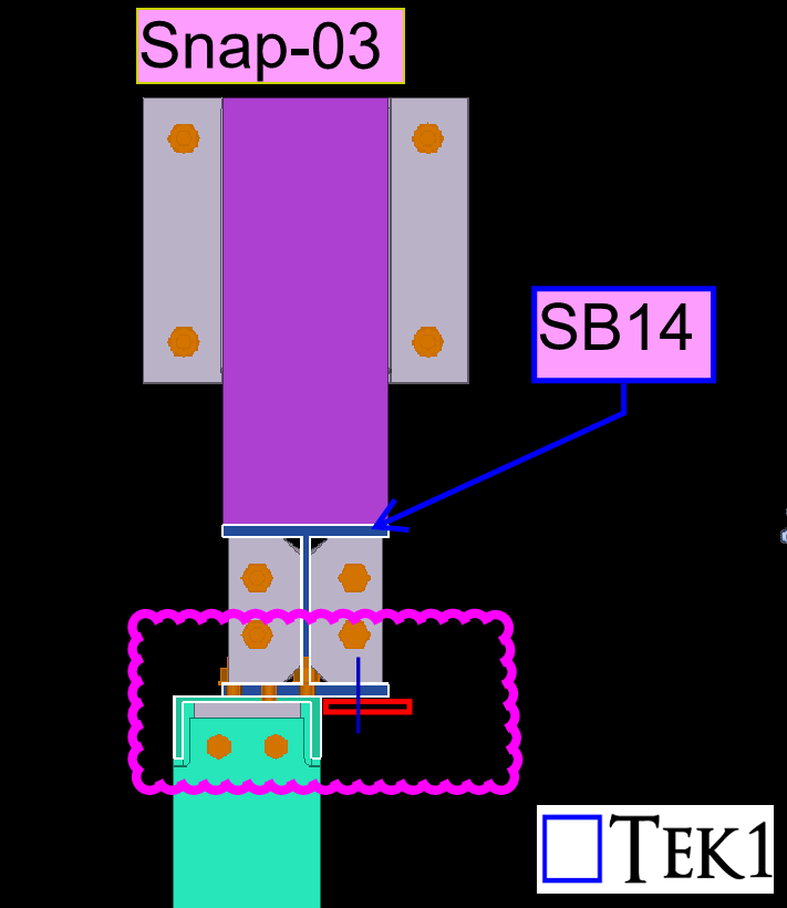
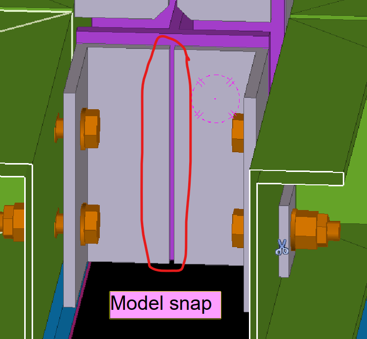
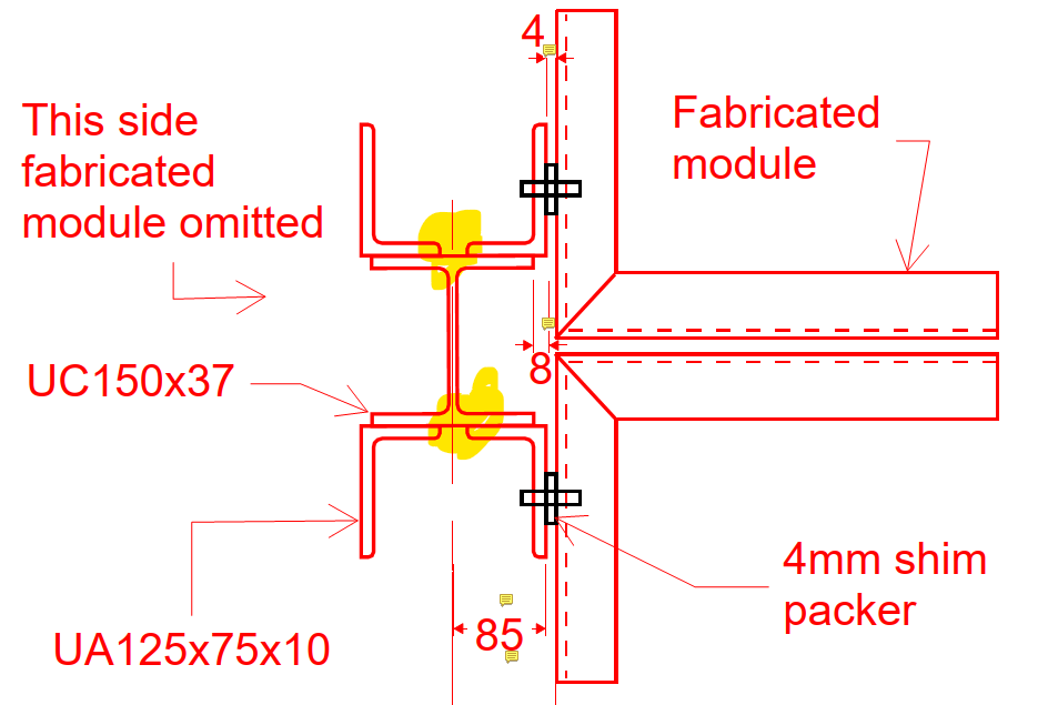
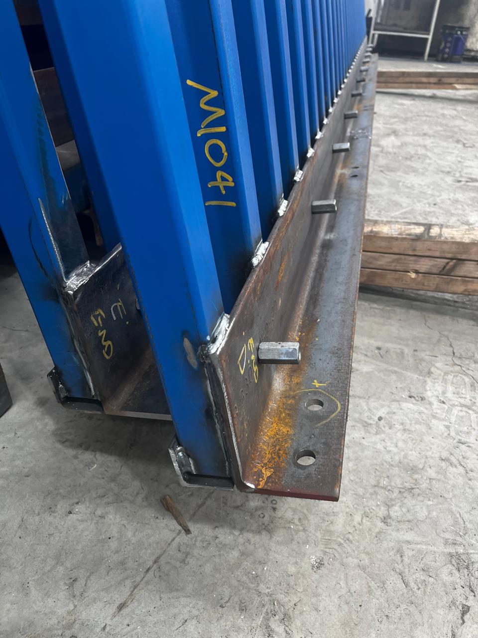
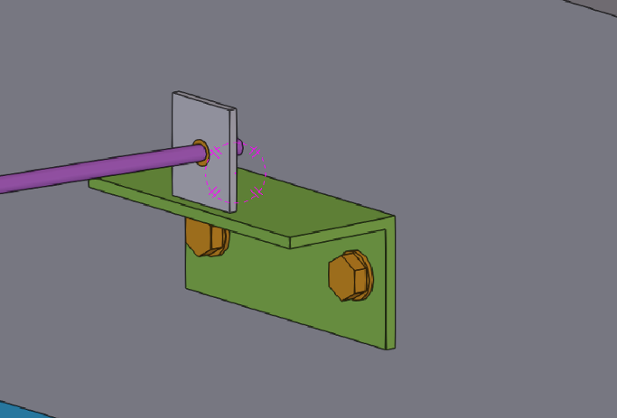
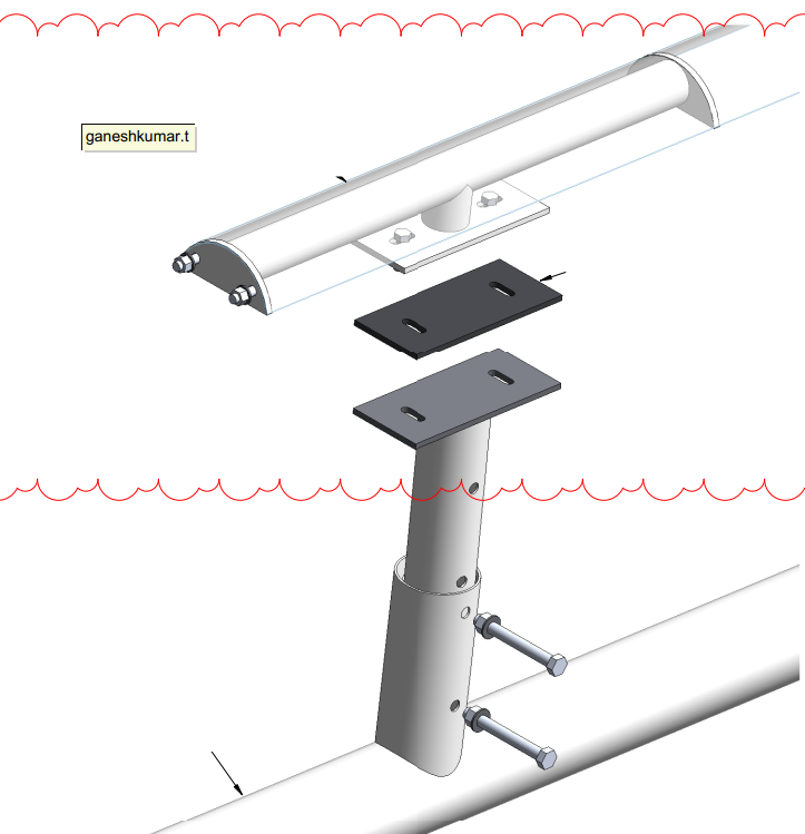
We identified this issue early in the detailing stage and proposed alternate connection details that would allow easier installation of the fireproofing sheets without compromising the structural requirement.
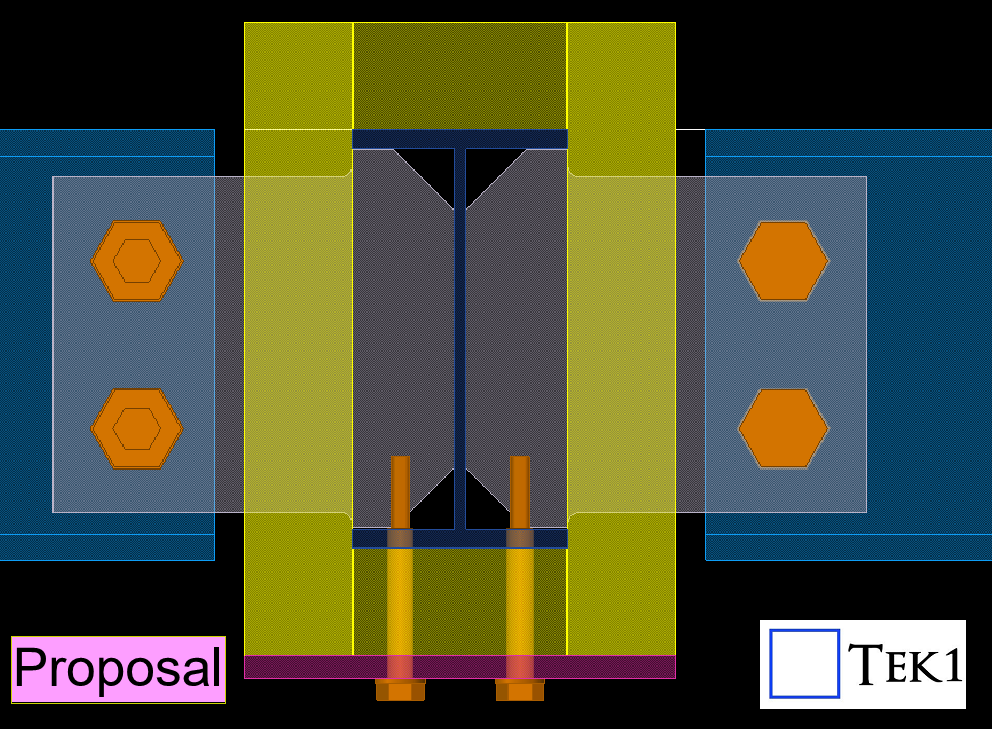
The engineer reviewed our proposal, suggested a few adjustments like thickness changes, and then approved our updated connection details.
Catching these issues early during detailing avoids major headaches later for installers and saves valuable time on-site
Stay with TEK1 for more updates on this sydney metro project