Tag: TEK1-GANESH-PROJECTS

  • Expert Steel Detailer looks beyond Structural Drawings

    Expert Steel Detailer looks beyond Structural Drawings

    Expert Detailing | Sydeny | Melbourne

    This blog focuses on a crucial aspect of detailing: collaborating with fabricators and understanding steel profiles.

    Structural engineers typically specify steel profiles based on their calculations. However, as detailers, we need to consider two critical factors:

    Product Availability: Is the specified material readily available in the market?

    Fabrication Feasibility: Can the profile be easily fabricated?

    Balancing these factors can save significant time and effort for both fabricators and detailers.

    Real-World Example

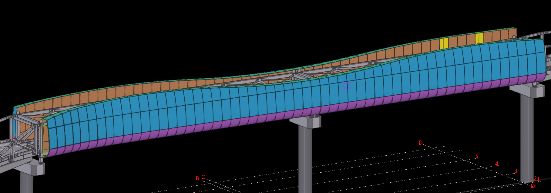
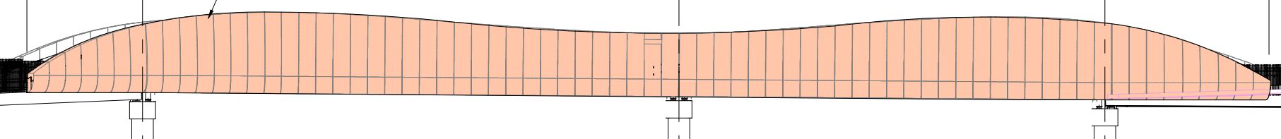
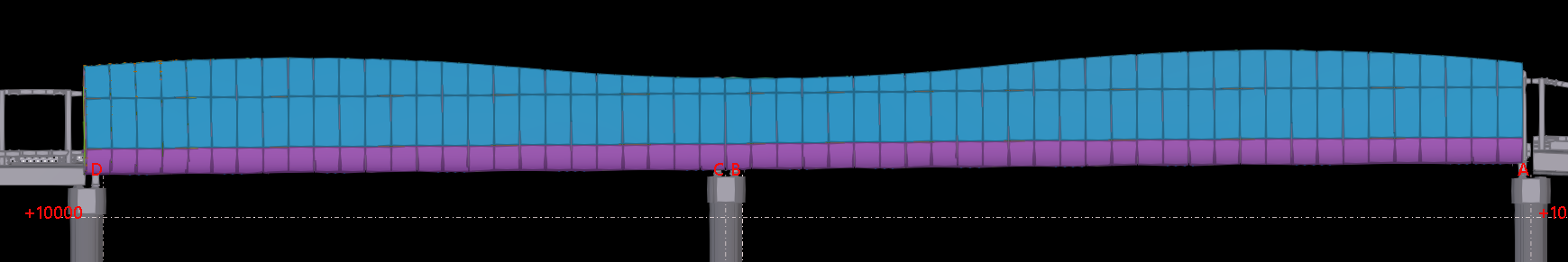
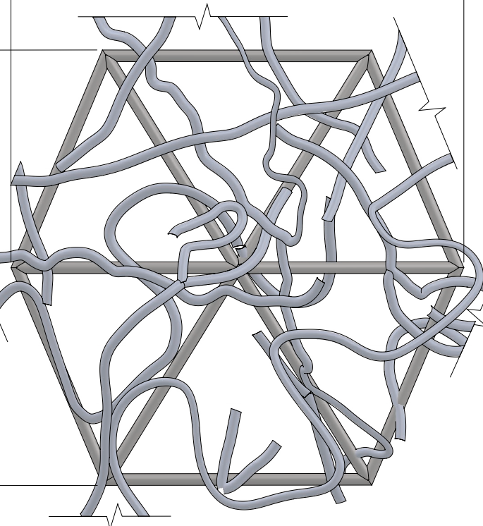
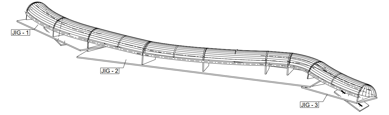
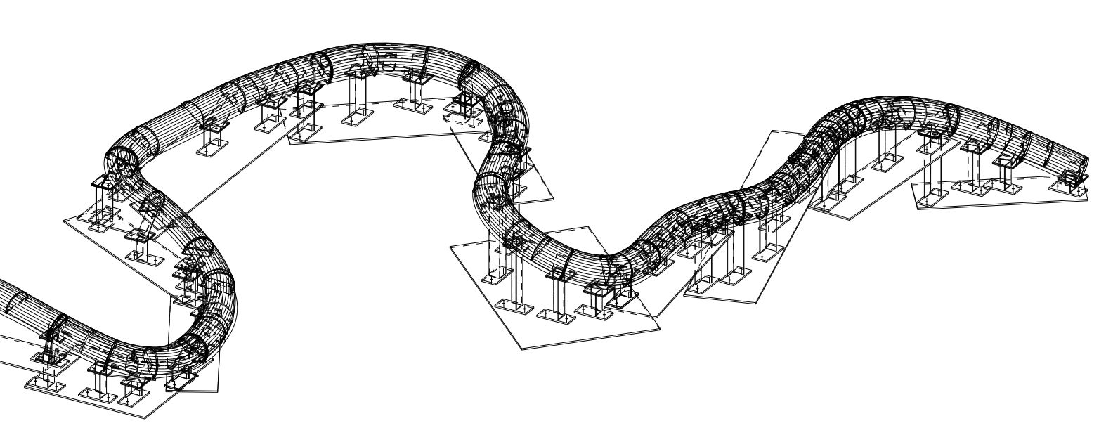
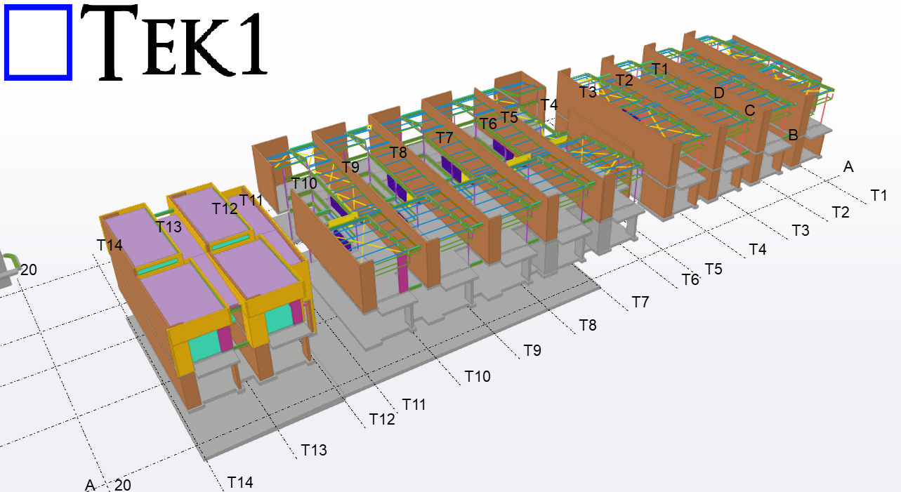
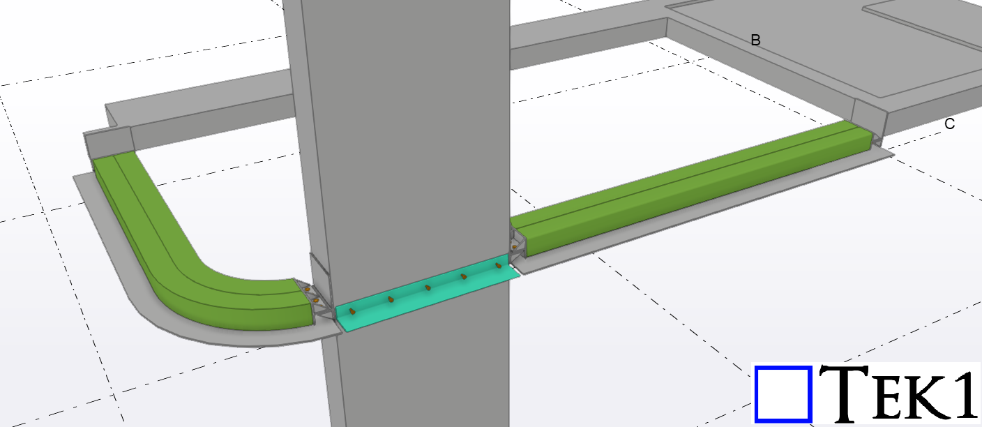
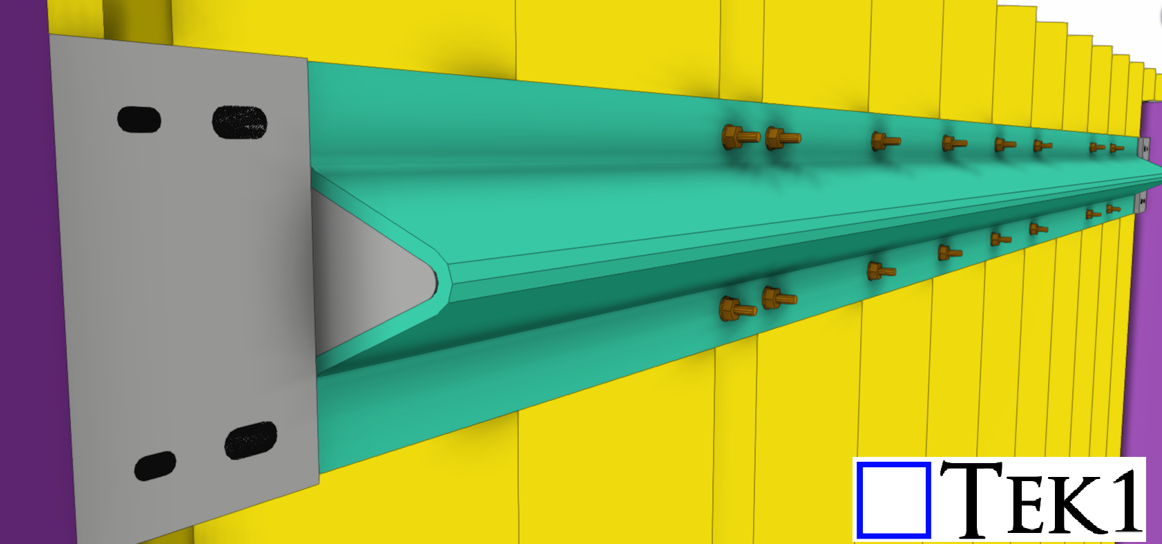
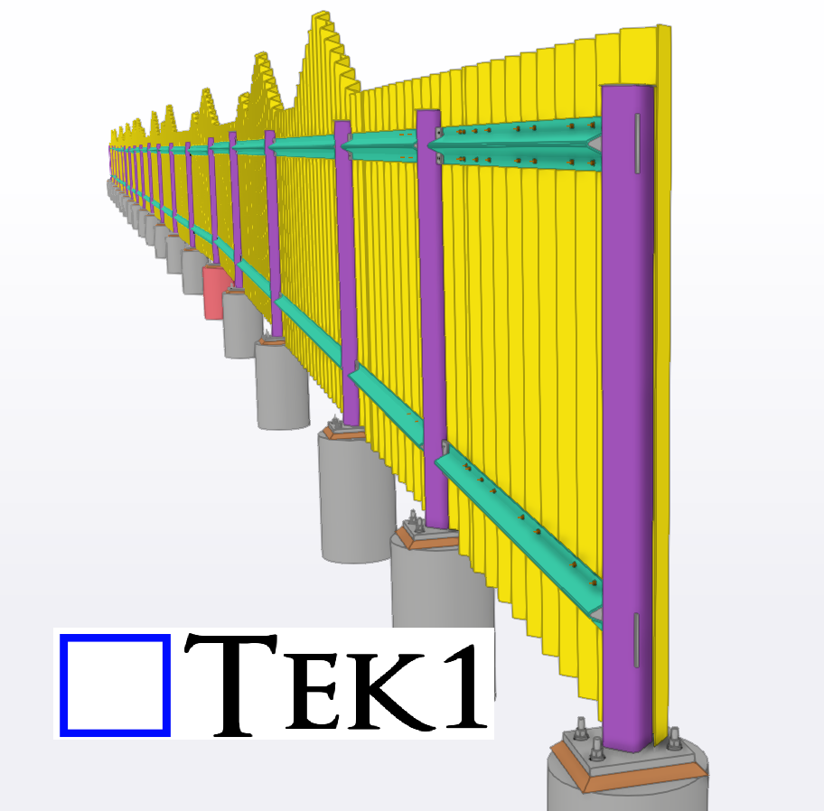
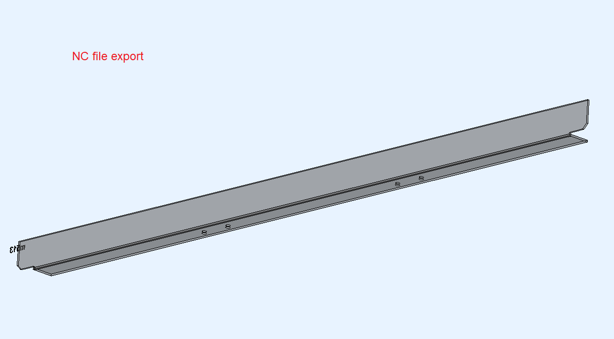
    In one case, an engineer specified a curved SHS (Square Hollow Section) beam.

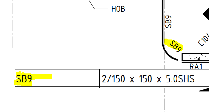
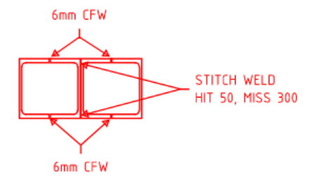
    While this profile met the structural requirements, bending an SHS beam is a challenging process .There are fabrication limitations. Instead, we suggested using two PFCs (Parallel Flange Channels), which are much easier to bend.

    Before making the change, we sought the engineer’s approval, and they confirmed the modification. By doing so:

    • We avoided delays in fabrication.
    • We ensured the project stayed on schedule.

    Why This Matters

    If we had followed the original design without questioning it, the fabricator would have requested changes due to the difficulty of bending an SHS beam. This would have caused delays and disrupted the project timeline.

  • Vent Holes in Steel Detailing

    Vent Holes in Steel Detailing

    During a recent client visit, we encountered an issue with the size of vent holes. In Australian detailing, we typically use a standard catalogue for specifying galvanizing holes. We followed this standard and provided the holes in the end plate accordingly.

    Adequate venting at correct location is very important for efficient galvanizing

    However, the client pointed out that the caps used to seal these holes after the galvanizing process did not fit. This was the first time we faced this issue, and it highlighted a crucial point.

    Key Takeaway

    When providing galvanizing holes, it’s essential to confirm the hole size with the client rather than relying solely on the standard catalogue. This approach ensures compatibility with the caps used and can save a significant amount of money by preventing rework.

    By aligning specifications with client requirements from the outset, we can avoid similar issues in the future and ensure a smoother project execution.

  • How an Experienced Detailer Can Save on Rework

    How an Experienced Detailer Can Save on Rework

    At TEK1, our extensive experience in detailing bridge projects has equipped us with the knowledge and foresight to minimize rework. Recently, we have been detailing two bridges for a leading company in Australia. Here’s a glimpse into how our expertise can prevent costly mistakes and ensure smooth project execution.

    Addressing Cladding Design Challenges

    We received design drawings for the cladding around the bridges, one of which showed cladding with only one horizontal split at the bottom location, while the rest was a single piece. However, to facilitate easier handling and reduce the risk of damage, we identified the need for two horizontal splits instead of one.

    Why Split the Cladding?

    1. Handling Issues: Large, single-piece cladding can be difficult to manage in the shop.
    2. Material Sensitivity: The cladding is made from a small aluminum sheet with perforations, making it prone to damage.

    When modeling this type of cladding, it is crucial to consider the fabricator’s handling challenges and potential issues they might face.

    TEK1’s Proactive Approach

    Given our extensive experience with similar bridge projects, we anticipated these issues. TEK1 arranged for our detailers to visit the factory directly, allowing them to understand firsthand the difficulties fabricators might encounter.

    For this particular bridge job, TEK1 proactively raised queries about the maximum length of the cladding before starting the project. By addressing potential issues early on, we can significantly reduce the risk of rework.

    The Benefits of Experienced Detailing

    By leveraging our experience and proactive approach, TEK1 ensures:

    1. Enhanced Efficiency: By identifying and solving potential issues early, we streamline the fabrication process.
    2.Cost Savings: Minimizing rework leads to significant cost savings for our clients.
    3.Quality Assurance: Ensuring that the design is practical and feasible reduces the likelihood of damage and maintains high-quality standards.


    At TEK1, our goal is to deliver projects that not only meet client requirements but also stand the test of time. By understanding and addressing fabrication challenges, we ensure that our detailing work is both precise and practical, ultimately saving time and resources for everyone involved.

    Stay tuned for more insights and updates on how TEK1 continues to lead the way in bridge detailing and beyond.

  • EMU IN THE SKY:Branches creation

    EMU IN THE SKY:Branches creation

    We are detailing the Australia iconic project EMU IN THE SKY.

    There are branches everywhere around the globe. But none of them are straight. They are in different angle and different curves.

    Initially, we proposed creating molds for each branch type to make this branches shape, but the client preferred using jigs for shaping.

    Our Solution: Angles and Plates for Jigs

    After careful planning, we suggested using angles and plates for the jigs due to their:

    1. Availability and Cost: Easily available and more affordable than other profiles.
    2. Reusability: The jigs can be reused, enhancing cost-effectiveness.

    Our client accepted this approach and is now in the process of creating the jigs.

    Skilled Craftsmanship

    Creating these jigs is not a structural task but requires the expertise of a skilled detailer. The precision and craftsmanship involved ensure that the branches meet the project’s aesthetic and functional requirements.

    Project Progress

    As the project is still ongoing, we are unable to showcase the complete picture of the branches. However, we have provided some images from our model for your reference.

    Our Commitment

    At our company, our primary aim is to satisfy our clients’ requirements. Equally important is our commitment to minimizing costs and rework, which ultimately supports our goal of client satisfaction.

    Stay tuned for more updates on the EMU IN THE SKY project as we continue to bring this iconic vision to life.

  • New Market stage 2 – Randwick

    #Sydney Projects #Steel Detailing #Commercial Structures

  • Navigating Access and Slope Limits for Stairs and Ladders

    Navigating Access and Slope Limits for Stairs and Ladders

    When it comes to constructing stairs or ladders, adherence to specific standards regarding access and slope limits is paramount. Understanding these guidelines, as outlined by the Australian Standards AS1657, ensures not only safety but also compliance with regulatory requirements.

    1. Access Ramps and Pathways:

    If you require access for height without steps, the slope must fall within a minimum degree range of 0-20°, with a preferred range of 0-10°. Public access ramps in Australia typically adhere to a 4° slope, which, while effective, can consume a significant amount of landing area. This slope range is predominantly utilized for ramps and access pathways.

    2. Stairs in Residential and Commercial Settings:

    In residential and commercial areas, stairs are commonly employed, typically featuring a degree range between 30° to 38°. However, according to standards, stairs should ideally fall within the range of 20° to 45°. It’s important to note that stairs occupy a substantial amount of ground area and must be carefully designed for optimal functionality and safety.

    3. Industrial Ladders:

    Industrial settings often utilize step-type ladders, which should ideally have a degree range between 60° to 70°. Treads are commonly incorporated for enhanced safety and stability.

    In cases where clearance is limited, rung-type ladders may be employed. Rung-type ladders, with a degree range of 70° to 90°, offer a compact alternative, making them suitable for confined spaces. Notably, 90° ladders are commonly found in locations such as ships and network towers, requiring minimal space.

    Safety Considerations:

    It’s crucial to emphasize that the degree range between 45° to 60° is deemed unsafe for both ladders and stairs. This zone presents heightened risks and should be avoided to ensure the safety of users.

    In conclusion, adherence to prescribed access and slope limits is essential when constructing stairs and ladders. By following established standards, builders and designers can create structures that prioritize safety, functionality, and compliance with regulatory requirements.

    As detailers, everyone should be familiar with these standards. Even when architects or engineers overlook these details, a detailer can catch them. This is also one of the important aspects for detailers to remember.

  • Deer park -Noise wall

    Deer park -Noise wall

    Tek1 has successfully completed a commercial project for a reputable organization in Australia.

    The scope of work involved providing walls for the railway track. These walls are constructed using 3mm sheets, meticulously modeled to form zigzag patterns with varying heights, adhering to the provided design specifications.

    Additionally, detailed drawings, including unfolded views, were provided to the fabricators, accompanied by precise dimensions and folding angles, indicating the appropriate folding sides.

    With this comprehensive documentation, the fabrication process commenced smoothly, devoid of any missing dimensions or details. This efficient coordination not only saved significant time for the fabricators but also streamlined the construction process for the builders.

    As a result, the walls were erected within the scheduled timeframe, meeting project deadlines seamlessly. The client expressed high satisfaction with the quality and timeliness of our work, further affirming Tek1’s commitment to delivering exceptional outcomes.

  • Navigating Kick Plate Dimensions:Unveiling the Distinctions Between AS1428 and AS1657 Standards

    Navigating Kick Plate Dimensions:Unveiling the Distinctions Between AS1428 and AS1657 Standards

    In the realm of architectural and structural standards, the dimensions of kick plates play a crucial role in ensuring safety and accessibility.

    When it comes to ramps, AS1428 sets a minimum height requirement of 150mm for the top of the kerb rail from the floor. This standard aims to provide optimal support and guidance for individuals with diverse mobility needs.

    However, the story takes a nuanced turn when we shift our focus to stairs. AS1657, the standard specifically addressing fixed platforms, walkways, stairways, and ladders – dictates a different criterion.Here, the top of the kick plate is mandated to be at least 100mm above the floor.

    Navigating these standards requires a keen understanding of the specific contexts in which they apply, showcasing the meticulous nature of design considerations in the pursuit of both safety and inclusivity.

  • Tekla – Error in STP file export

    Tekla – Error in STP file export

    As a TEKLA user, this blog will help you prevent mistakes in the fabrication shop. It can also save a lot of costs for you if you read it fully.

    Some clients request STP files for fabrication purposes, but it’s important to note that there may be errors in the Tekla export. Generally, Tekla lacks a built-in option for the STP format. We use an extension called multi converter, obtained from the Tekla warehouse, for STP exports.

    But, unfortunately, some parts don’t export properly, and we’ve encountered issues in our project.

    Please see the below nc file snap for part no m513.

    But when we export the same part in multi converter for STP format , We have got some errors.Please see below snap.The exported STP file shows only a small part instead of the entire component.

    Most of the parts export successfully without any errors. However, a few parts with a maximum number of cuts are encountering issues, as shown in the snapshot. Therefore, I recommend checking the exported STP format files before sending, particularly for parts with a higher number of cuts in the model.

    We have contacted TEKLA support regarding this issue. Please wait for a while, and we will update you once we receive a response from them.