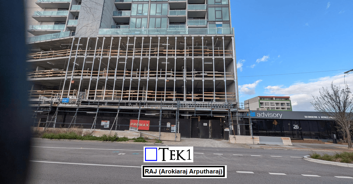
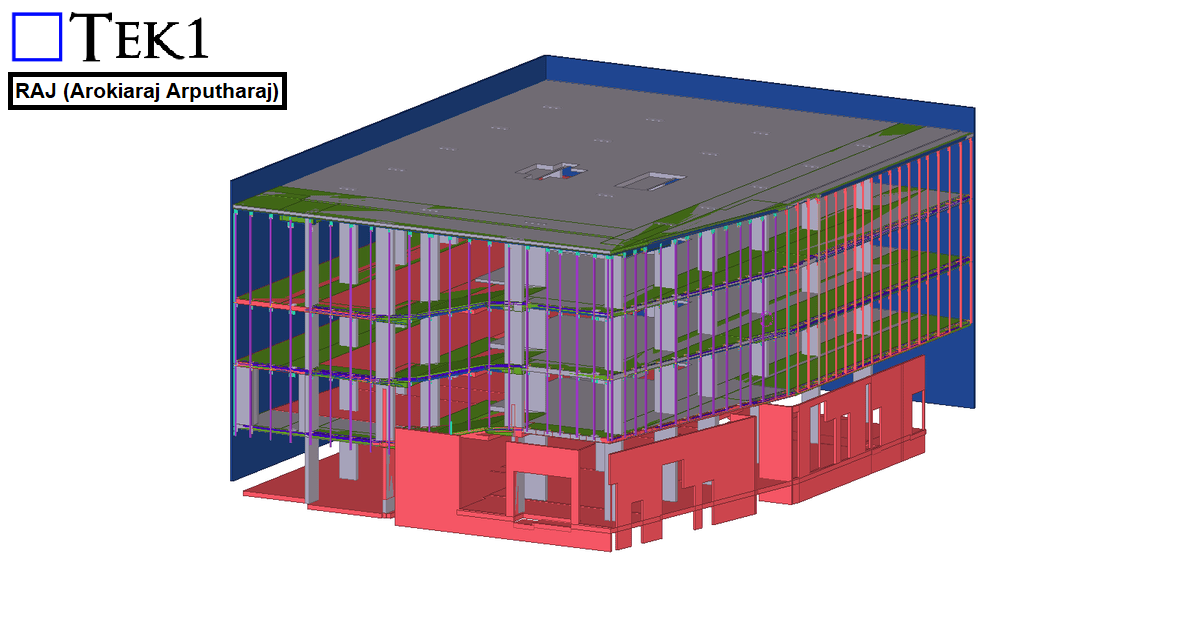
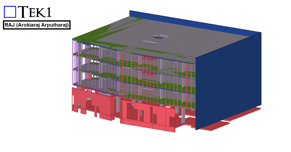
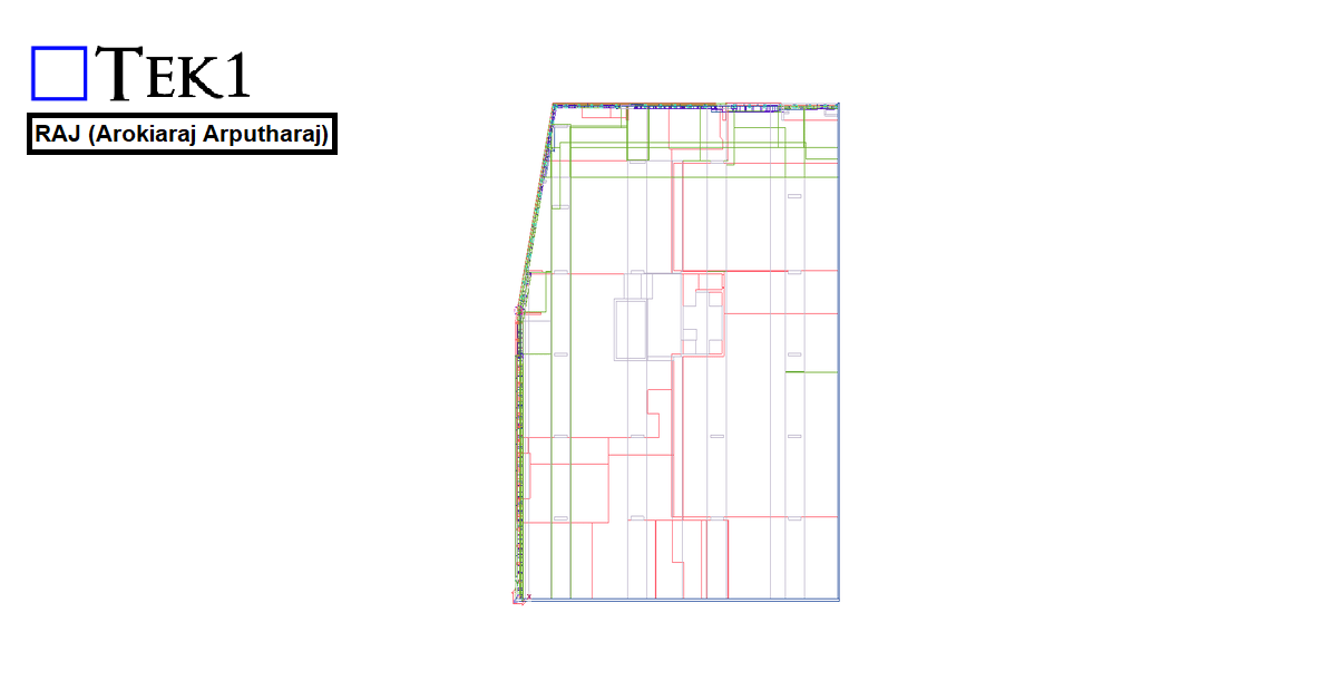
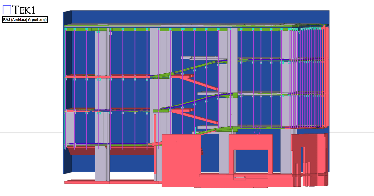
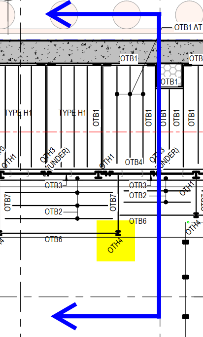
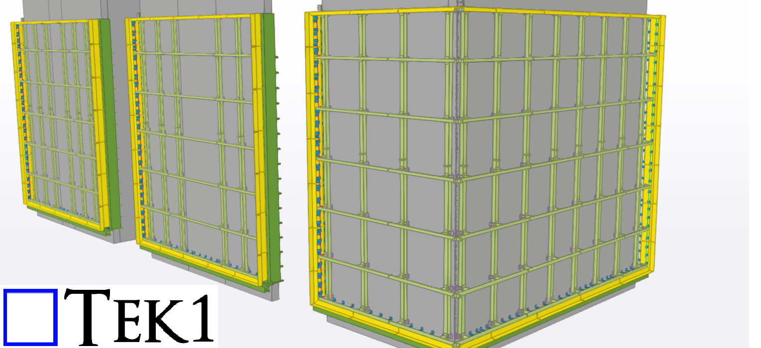
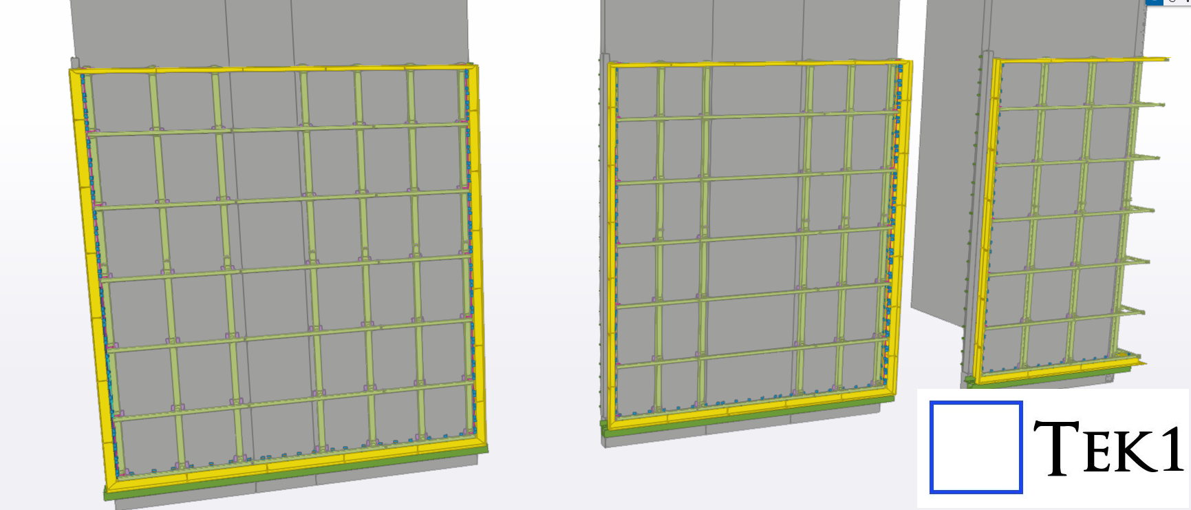
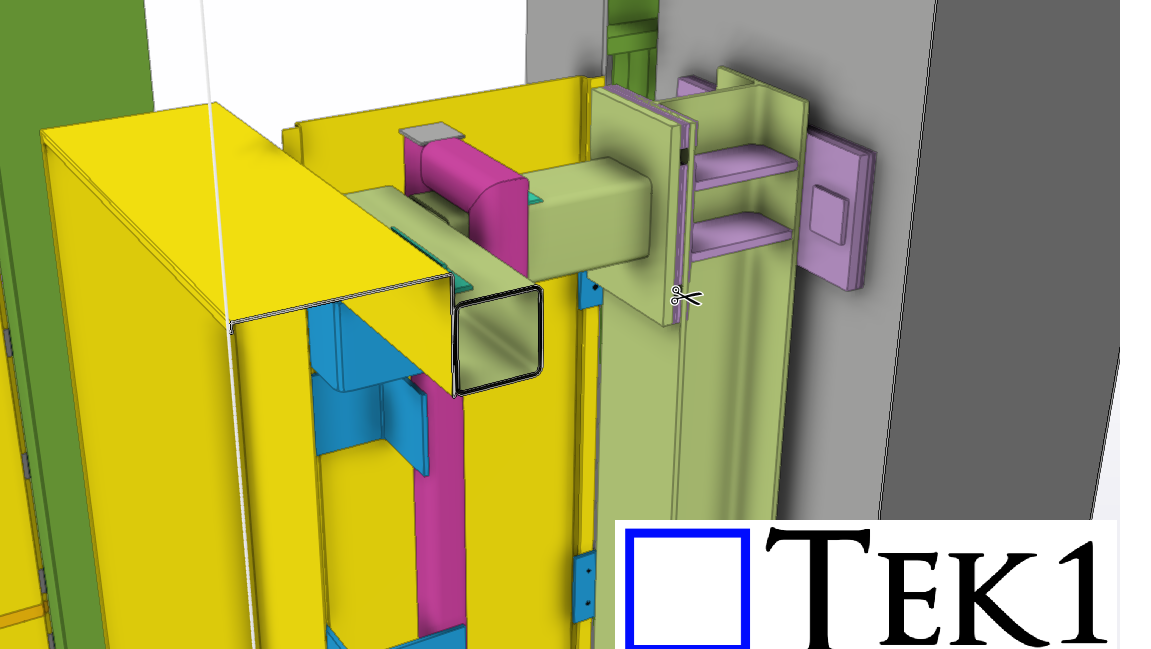
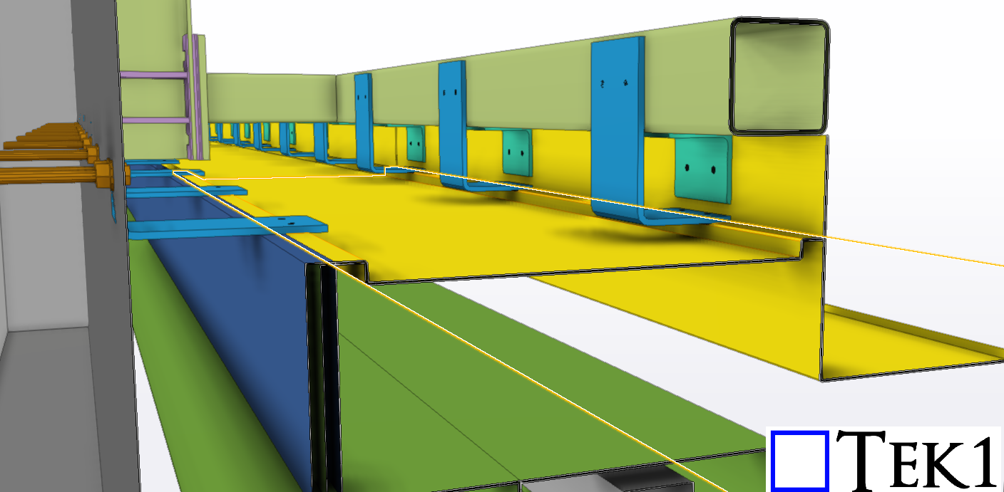
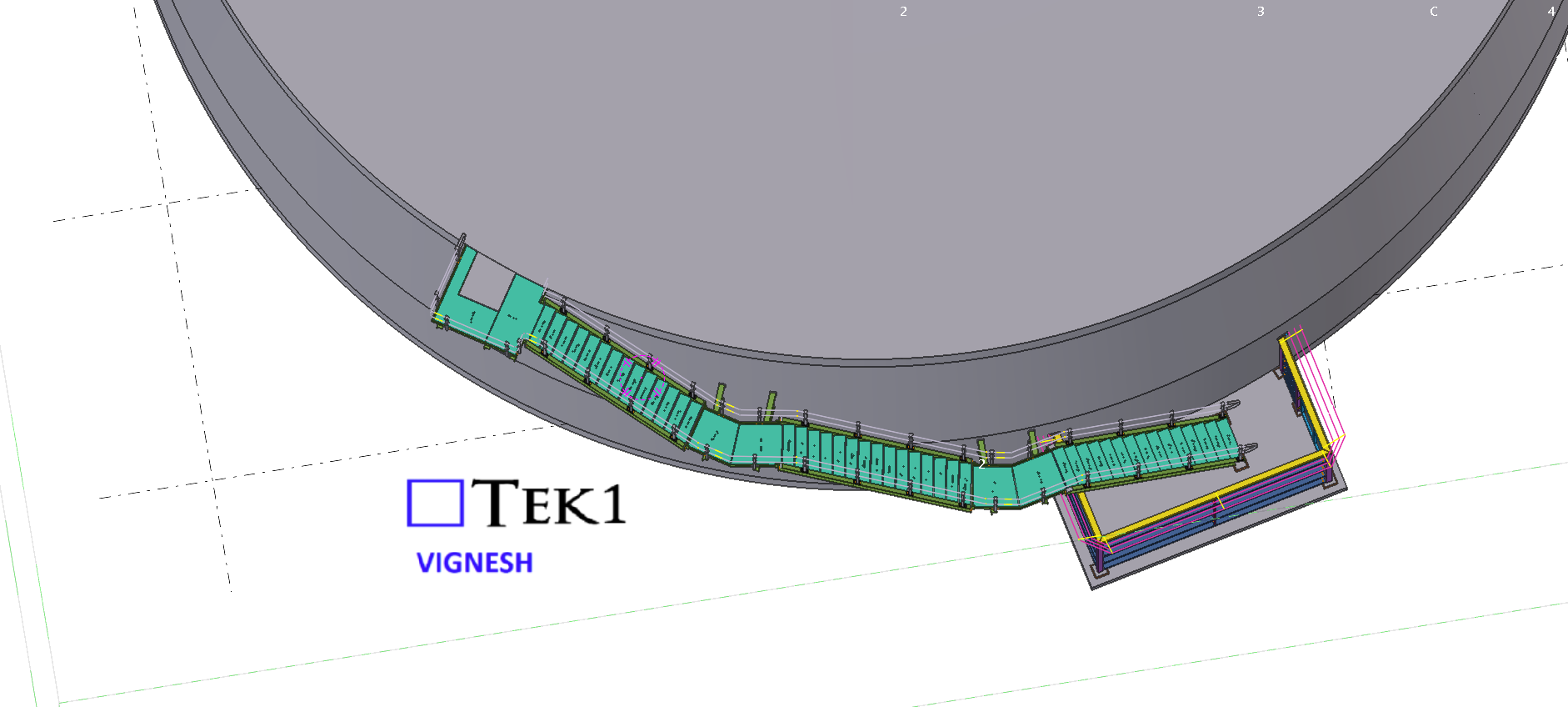
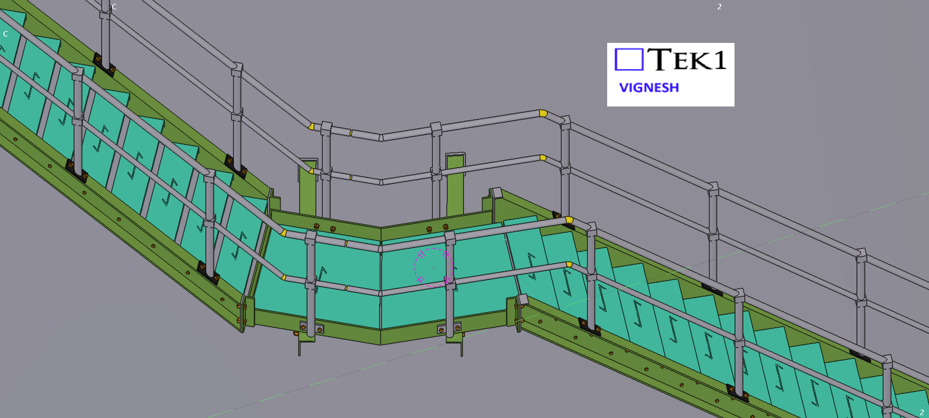
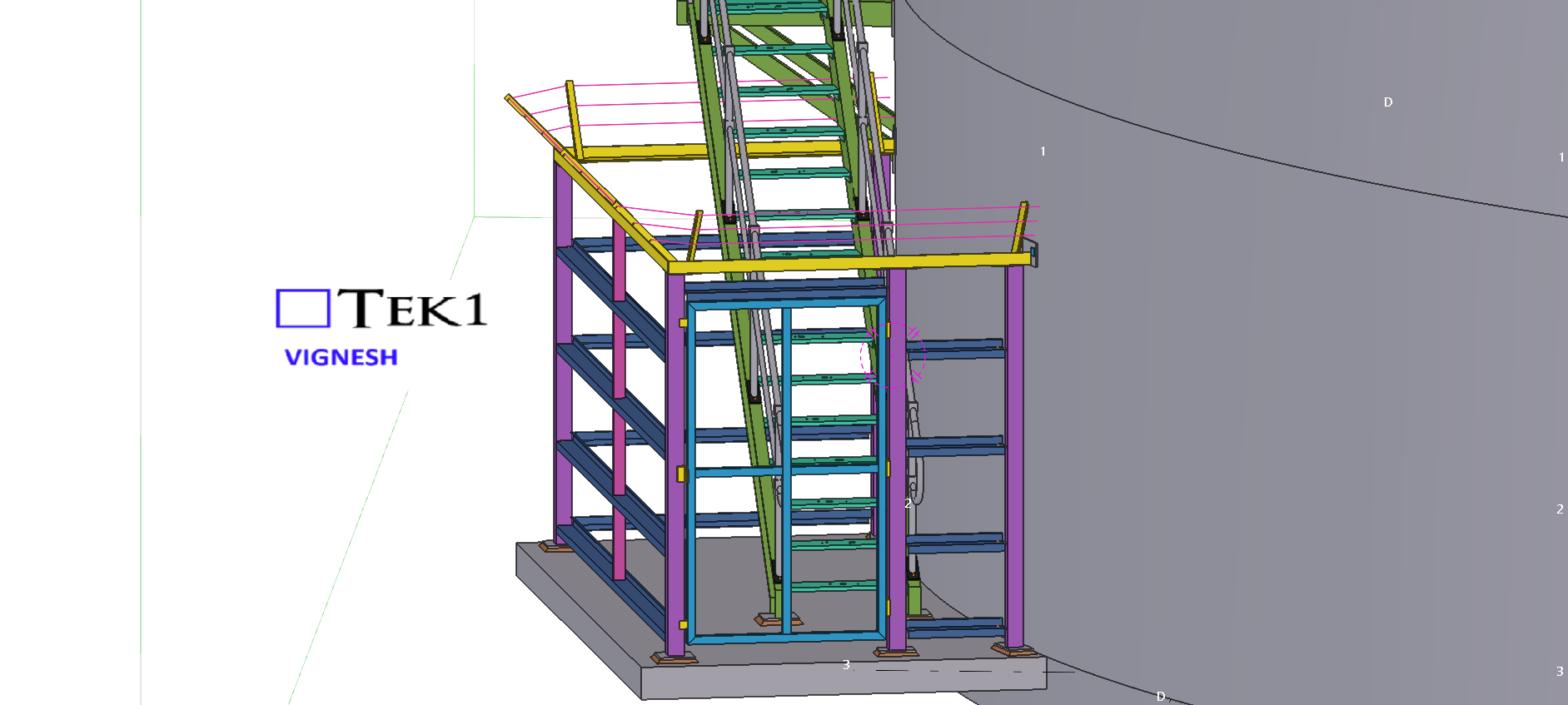
For the 27 Scott Street project, the client requested that the façade posts be installed with sufficient clearance so that the fixing anchors do not clash with the PT cable lines.
We carefully followed the client’s requirements and coordinated the design to ensure that the anchors clear the PT cable lines. The steel was successfully erected without any issues.
We would like to thank the client for giving us the opportunity to be part of this project.
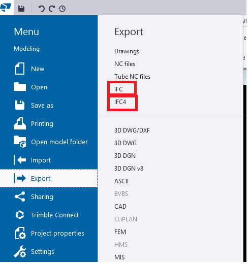
When we export models from TEKLA Structures, we mainly see two options:
Export IFC (this mostly means IFC2x3 format)
IFC4 Export
Both formats serve the same purpose—model interoperability—but they work differently, support different levels of data, and offer different quality of geometry.
In this blog, we explore the key differences, benefits, and when to use each format.
1. What is “Export IFC” (IFC2x3)?
This is the old IFC format used by most companies for many years.
Key points
Works in almost all BIM software
Shows Geometry is basic and sometimes rough
Limited property information
The File size is Bigger
Best For
✔ General coordination ✔ Clients who request IFC2x3 ✔ Old software compatibility
2. What is “IFC4 Export”?
This is the newer and more advanced format.
Key Points
Geometry looks cleaner and smoother
Curved members (Hollow sections, pipes, elbows, etc.) look perfect
More detailed data (bolts, welds, assemblies)
Smaller file size in many cases
Better for new BIM tools
Best For
✔ Modern BIM tools ✔ Better visual quality ✔ Detailed model sharing
3. Quick Comparison
Feature
IFC2x3 (Export IFC)
IFC4
Geometry
Basic (Rough)
Smooth & Accurate
Curved Shapes
Approximate
Perfect & Precise
File Size
Larger
Smaller
Compatibility
Very High
Medium
Details
Limited
More Detailed
convert IFC object to Steel Member
Work well
Can’t convert
4. Which One Should You Use?
Use Export IFC (IFC2x3) if the client asks for it or if compatibility is important.
Use IFC4 if you want cleaner geometry and more detailed information.
5. Final Summary
IFC2x3 (Export IFC) → Best for compatibility
IFC4 → Best for quality and smooth geometry
If your client or BIM Execution Plan (BEP) does not specify the format, use IFC4 for best geometry
When detailing steel, one important factor that’s often overlooked is the stock length of the beams. Confirming this early can prevent major rework later in the project.
Recently, we worked on a façade support steel project that involved several CHS beams. Normally, CHS sections are available up to 12 meters in length. However, in this case, the client informed us that for smaller CHS sizes, the maximum available length was only 6.5 meters.
Please see the below email from the client.
“Hi Ganesh
Have just noticed some of your Member lengths for the 101 CHS are longer than 6.5m stock lengths.”
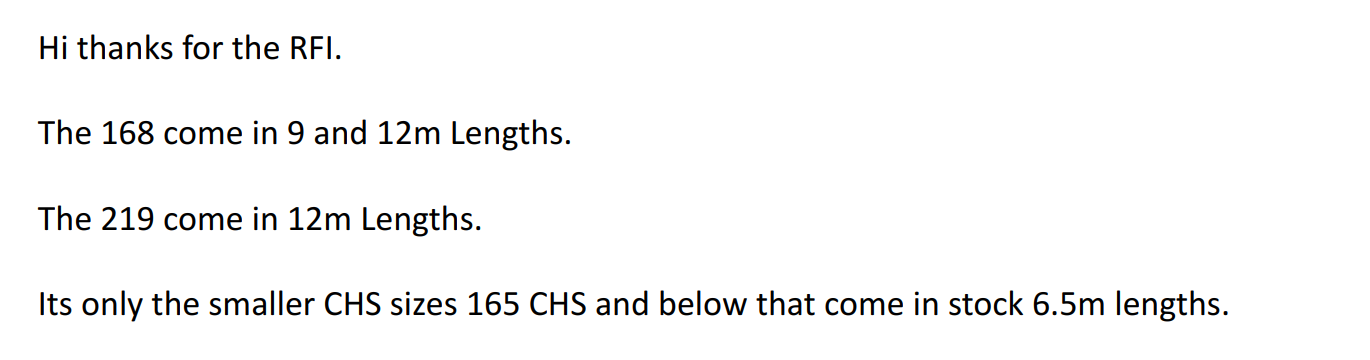
Then we have raised RFIs for the stock lengths. See the below replies from the client.
Always confirm the available stock lengths with the client or fabricator before starting the detailing. Early coordination like this saves time, reduces rework, and ensures a smoother fabrication process.
In this blog, I’d like to share an issue we faced related to hanger locations.
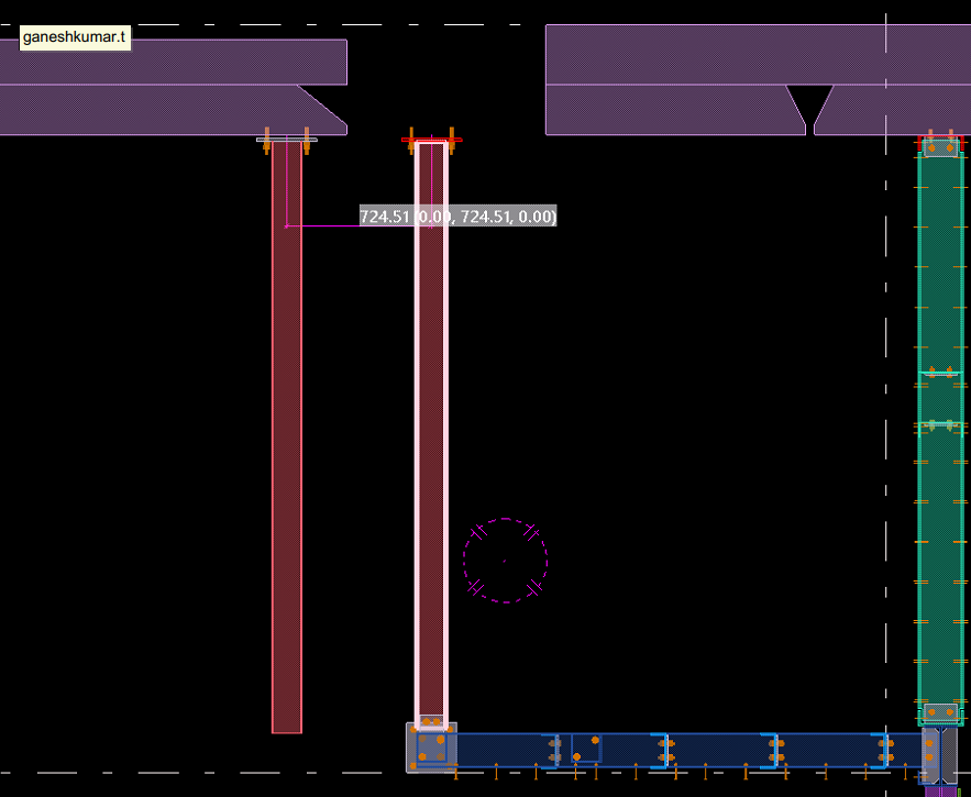
In this job, the floor steel was supported from the slab soffit. Initially, we placed the hangers as per the design drawings. However, during coordination with the concrete model, we discovered a slab void exactly at one of the hanger locations — meaning there was no concrete support available for that hanger.
Fortunately, we identified the issue before fabrication and raised it with the respective manager for correction.
When detailing steel, especially hangers or supports connected to concrete, it’s crucial to check the concrete model. Focusing only on the steel scope can lead to such clashes. Always verify slab and concrete details at the steel connection points to avoid costly rework later.
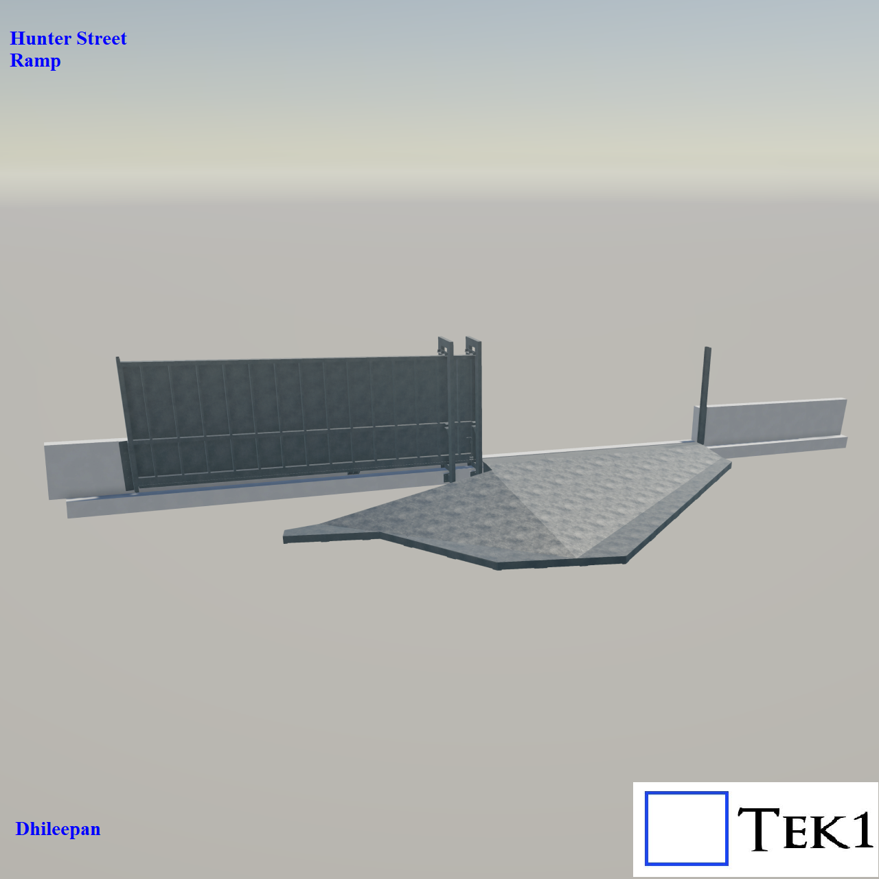
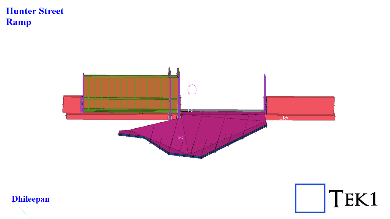
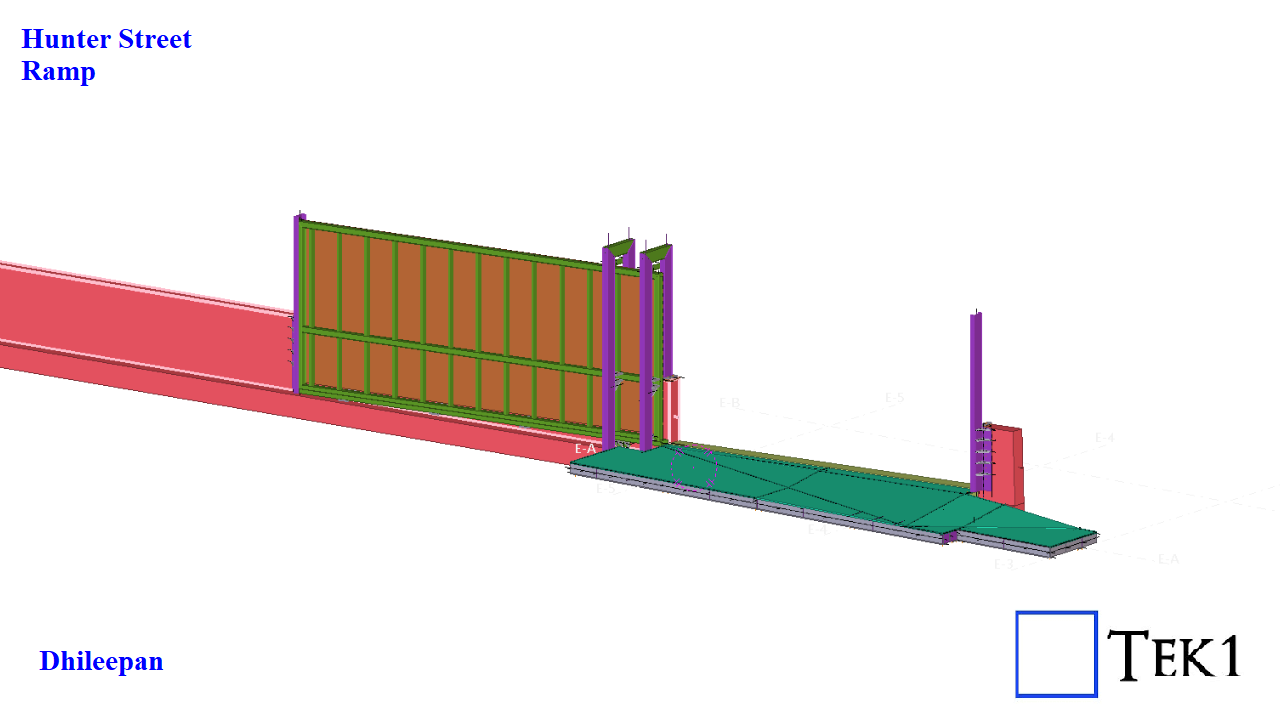
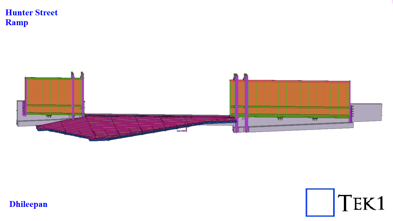
The Hunter Street Project involves a total of three unique ramp and gate assemblies, each designed with a distinctive geometry and function.
Unlike conventional ramps that slope in a single direction or follow a straight alignment, these ramps are far from ordinary. Each one features multiple slopes and apex lines, requiring precise modeling and coordination to achieve seamless transitions and accurate fitment on site.
The associated gate systems include both single-leaf and double-leaf sliding gates, each integrated carefully with the ramp slopes to ensure smooth operation and proper clearances.
Structurally, each ramp is composed of a series of 4 to 8 frames. Every frame includes:
A chequer plate deck at the top for slip resistance and durability.
A base plate at the bottom for connection and stability.
Waffle-type stiffeners sandwiched between, providing rigidity while minimizing weight.
This setup requires engineering precision and modeling expertise. Tek1 had to provide inputs and suggestions to design the slopes in a way that ensures smooth operation of the sliding gates without imbalance.
TEK1 recently completed a media wall support project for a prominent organization in Australia. The goal was to provide detailed support steelwork for a large media wall screen — with a unique challenge.
Unlike most projects, we didn’t receive any structural design drawings. Instead, we were given only a concept design, leaving it to TEK1 to determine suitable steel profiles and connection details.
Our team carefully studied the concept and nominated appropriate profiles for each connection based on feasibility, strength, and ease of fabrication. Once the detailing was complete, we submitted it to the structural engineer for review.
The engineer approved our detailing with minimal changes, which helped speed up the process and made things easier for the client. The use of different profile types also optimized the design for practicality and efficiency.
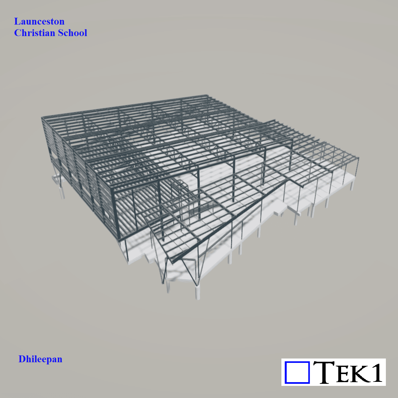
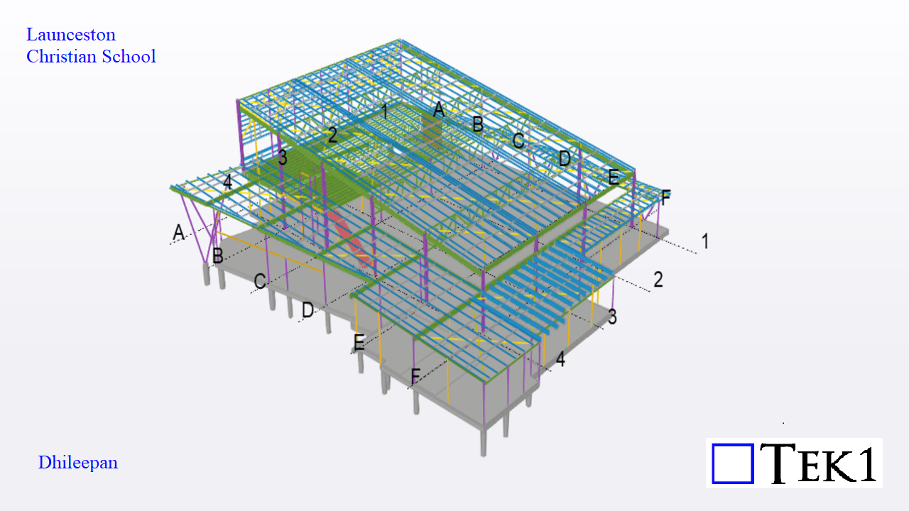
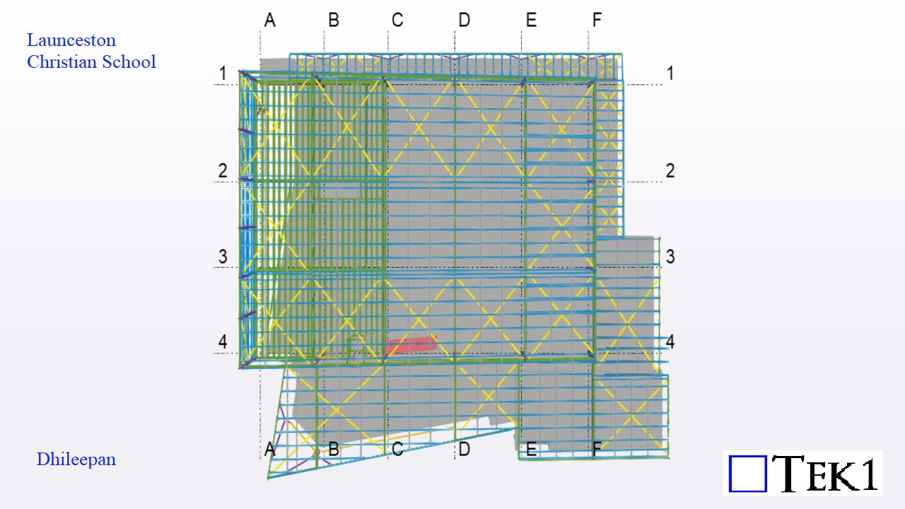
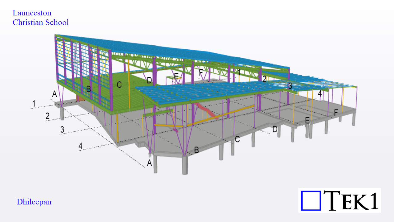
Let’s dive into the exciting expansion at Launceston Christian School in Tasmania—a thoughtfully designed new building covering an area of 1,440 square meters. This structure adds essential facilities to the campus, including classrooms, an auditorium, a storage room, and a library.
Challenges:
A key engineering challenge in this project was related to the cast-in base plates. These base plates had to be finalized and fabricated before the slab pour could begin. This required us to release accurate base plate fabrication drawings and exact location details early in the project timeline.
Since altering column positions later would not be feasible—especially if rafter alignments or other components demanded changes—we had to finalize all column locations at the earliest stage. This meant that the column modeling had to be both precise and quick.
Once the column layout was locked in, the modeling of the beams and girts progressed smoothly without any complications.
This project serves as a great example of how early coordination, clarity in design, and proactive decision-making contribute to successful structural outcomes.
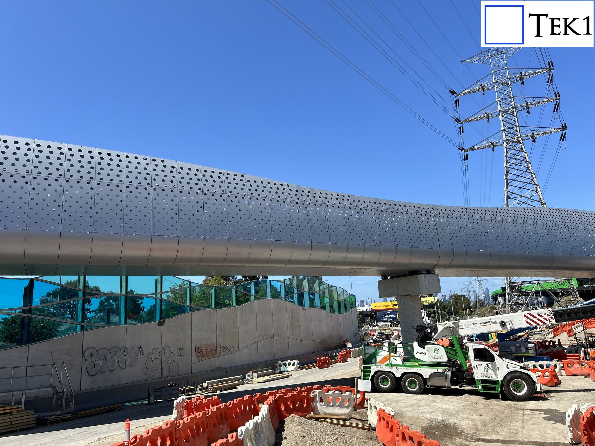
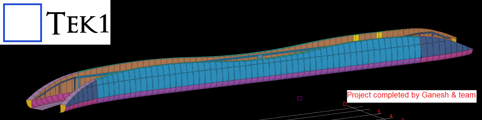
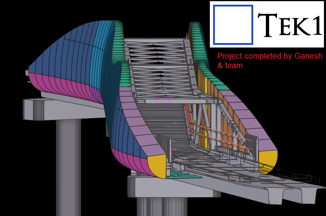
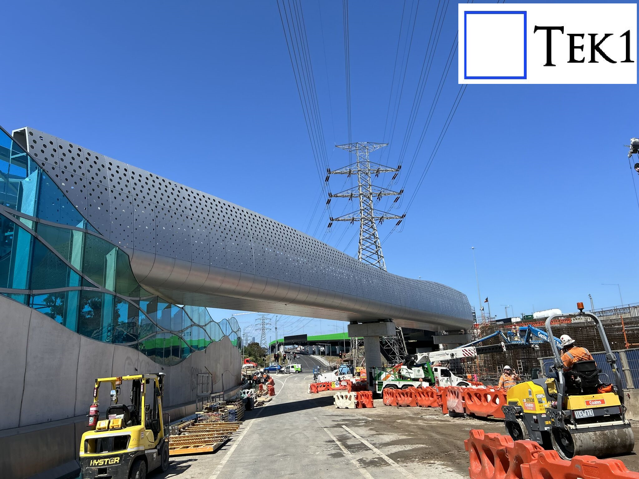
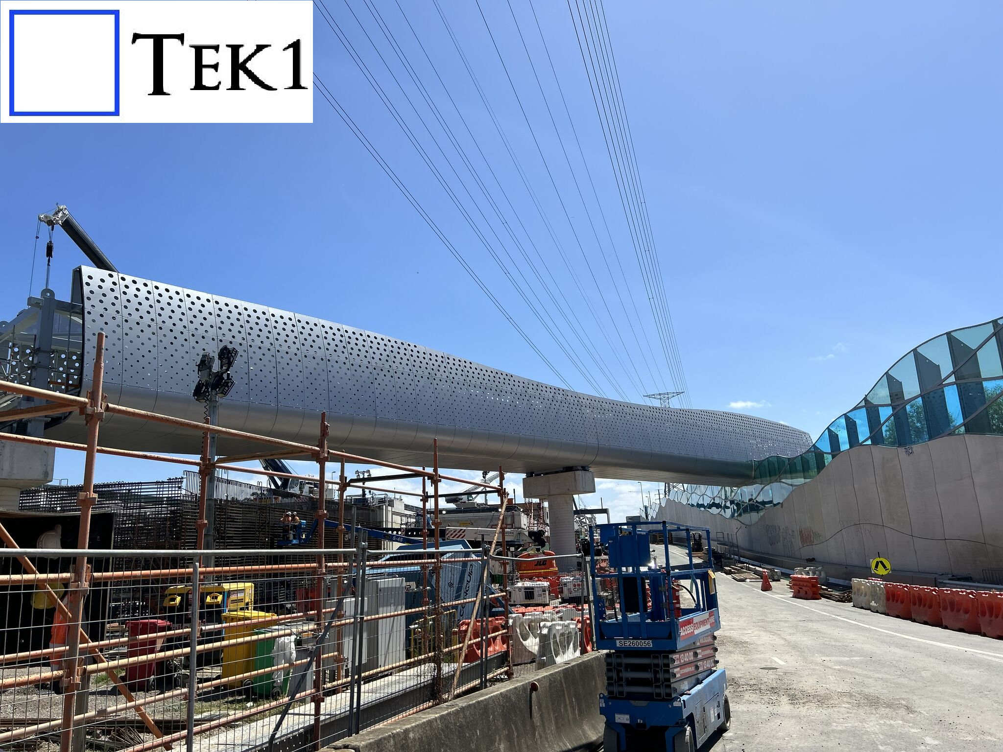
Tek1 recently completed a cladding project for a prominent organization in Australia. The project involved detailing cladding and its support system around a footbridge with unique challenges.
The footbridge featured curved ends, but these were not simple linear curves, making the design and detailing process particularly intricate.
Tek1 conducted numerous meetings with the client and engineers to finalize the cladding’s shape and ensure it met both aesthetic and structural requirements. This collaborative approach ensured the project’s success.