Tag: #TEK1-PROJECTS

  • SYDNEY METRO CITY & SOUTHWEST TUNNELGRC PANELS & ITS BRACKET

    SYDNEY METRO CITY & SOUTHWEST TUNNELGRC PANELS & ITS BRACKET

    TEK1, we recently had the opportunity to detail GRC panel brackets for a section of the Sydney Metro Tunnel, utilizing a point cloud survey to ensure precise alignment and installation.

    Project Overview

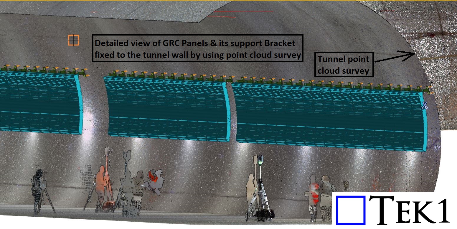
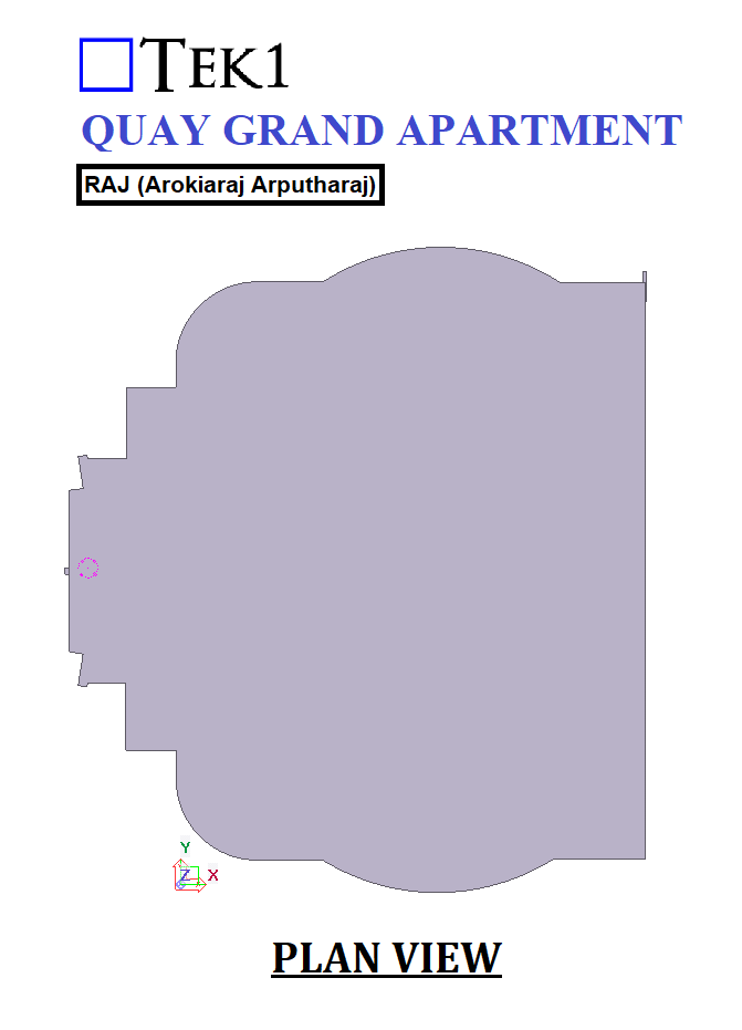
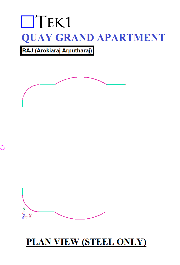
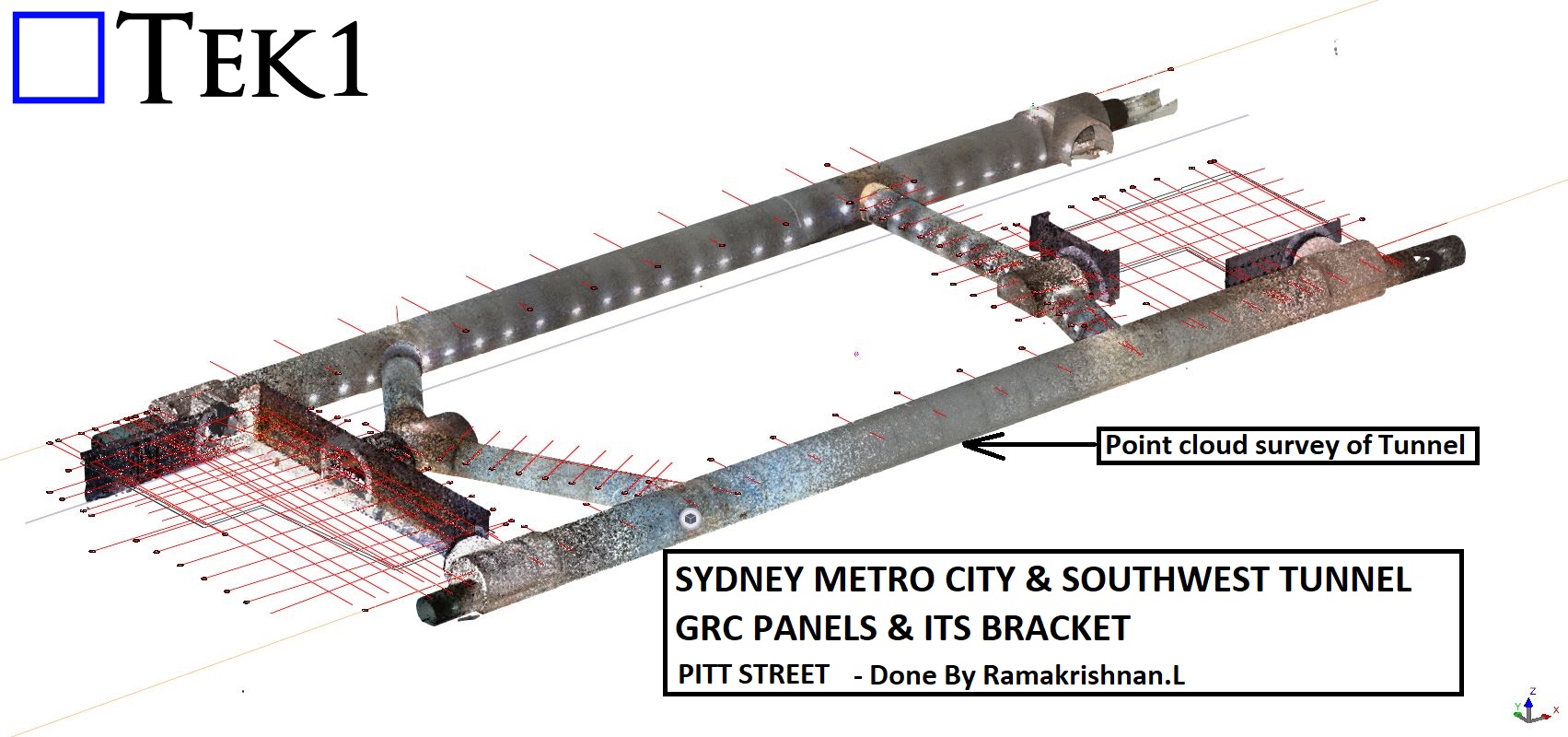
    The client provided a point cloud survey of the tunnel, allowing us to accurately determine the placement of GRC panels and their supporting brackets. Since tunnel walls are rarely perfectly straight—often featuring irregularities, ups, and downs—extra attention was required to ensure each bracket was positioned correctly for a seamless fit.

    Challenges & Solutions

    Efficient Coordination – By leveraging point cloud technology, we minimized potential site adjustments, streamlining the installation process for our client.

    As-Built Adjustments – The natural deviations in the tunnel wall’s shape meant that standard placements wouldn’t work. The point cloud data helped us fine-tune the bracket positions to match real-world conditions.

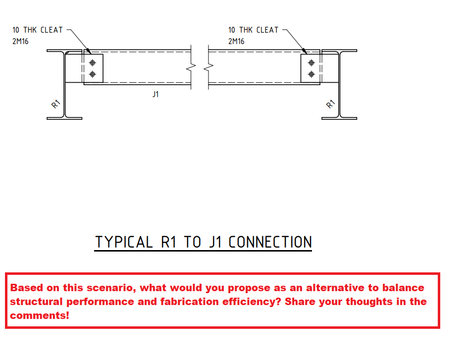
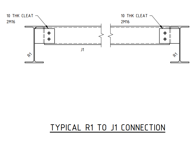
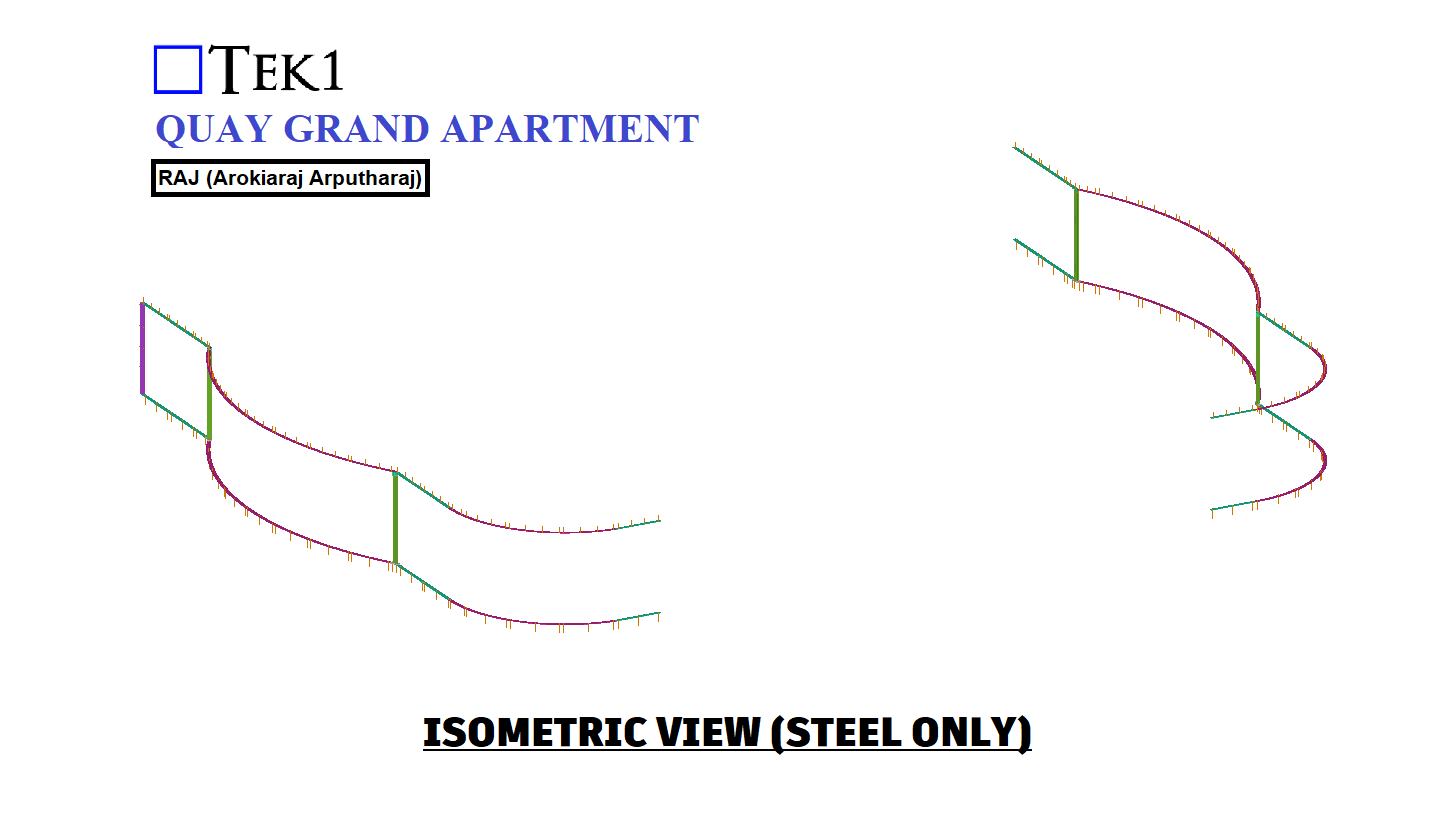
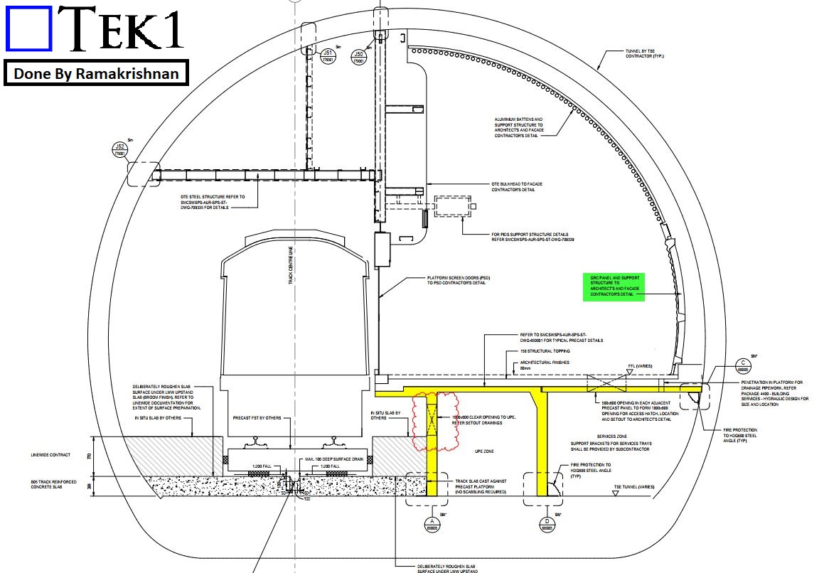
    Precision Detailing – Each steel bracket was meticulously detailed to accommodate the GRC panels, ensuring a secure and uniform installation.

    Conclusion

    Working with as-built tunnel walls requires high accuracy and adaptability, and this project was a great example of how TEK1 effectively integrates advanced technologies like point cloud surveys into our detailing process.

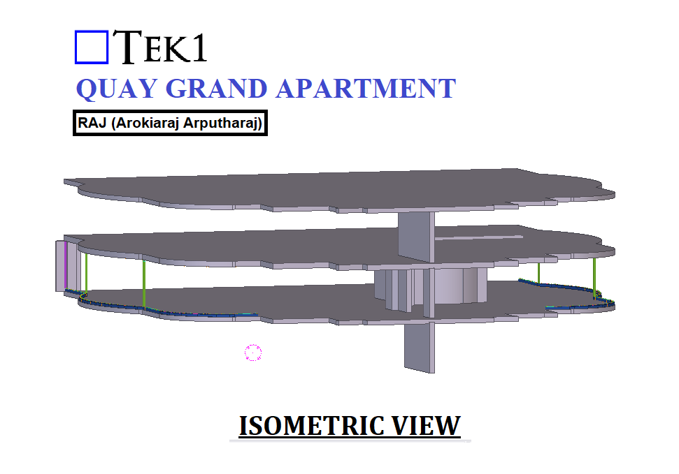
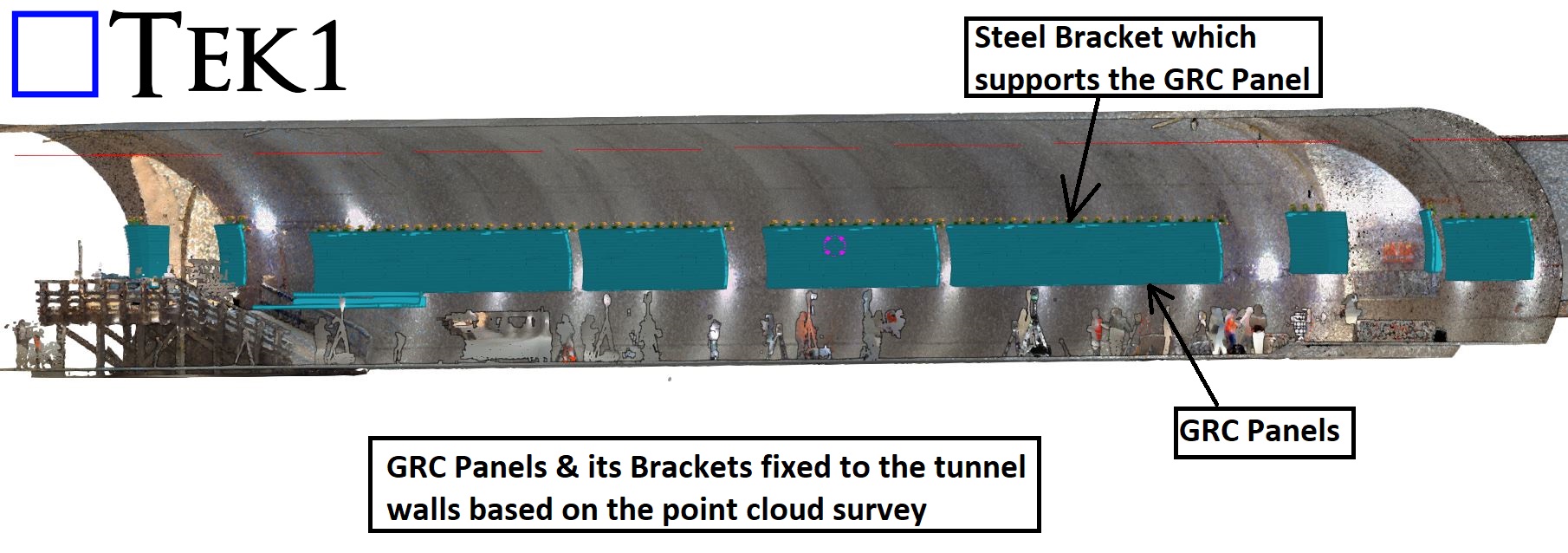
    Check out the snapshots below to see how the GRC panels are securely fixed to the tunnel wall using custom steel brackets.

  • Understanding PFC Shear Connection: A Practical Discussion

    Understanding PFC Shear Connection: A Practical Discussion


    Based on this scenario, what would you propose as an alternative to balance structural performance and fabrication efficiency? Share your thoughts in the comments!

    Introduction

    Shear connections play a crucial role in structural steelwork, ensuring the stability and strength of a framework. One common method is the extended shear plate connection, as seen in the R1 to J1 connection detail. However, this method introduces bolt eccentricity, which could impact the overall efficiency of the joint.

    The Challenge

    In the given design, the PFC (Parallel Flange Channel) shear connection is detailed using an extended shear plate. While this is a standard approach, it inherently results in increased eccentricity due to the offset load transfer through the bolts. This can lead to additional bending moments in the connection, requiring careful consideration in the design phase.

    Possible Solution

    A potential improvement is to introduce a cope in the PFC section and utilize a simple shear connection instead. This modification would:

    • Reduce bolt eccentricity
    • Simplify force transfer
    • Enhance structural performance

    However, this approach was not accepted by the client due to fabrication ease considerations.

    Key Learning for Junior Engineers

    This case highlights a key engineering principle: design optimization vs. fabrication practicality. While structural efficiency is paramount, practical considerations such as ease of fabrication, cost, and site constraints often dictate final design choices.

  • Erection Issue Eliminated Through Suggested Changes in the Splice Connection During Detail Engineering

    Erection Issue Eliminated Through Suggested Changes in the Splice Connection During Detail Engineering

    Issue Identified During Detail Engineering

    • During detail engineering, it was identified that the design specifies both-side web plates, with shop weld on one side and field bolts on the other.
    • This would have created a field erection issue, as the shop-welded web plate on both sides prevents secondary beam placement.

    Proposed Solution: Fully Bolted Connection

    • Use bolted connections on both sides instead of welding one side.
    • This allows the web plate to be shipped loose, making field installation easier.
    • At the site, the secondary beam can be placed first, followed by the web plate installation and bolting.
    • Factory-drilled holes ensure precise alignment and better quality.
    • Eliminates on-site welding hazards and inspection issues.

    Client Approval

    • The client accepted the suggestion due to its practical benefits and ease of installation.
    • The change improves efficiency, cost-effectiveness, and safety.

    Conclusion

    • Switching from welded-bolted to fully bolted improves constructability.
    • Ensures stronger, safer, and more efficient structural connections.
    • Small design changes can greatly impact project success.
  • TEK1’s Steel Detailing for Sydney Metro – Resolving Design Challenges – 1

    TEK1’s Steel Detailing for Sydney Metro – Resolving Design Challenges – 1

    TEK1 is currently engaged in steel detailing for the Sydney Metro project, working with a reputed organization in Australia. During the detailing process, we have encountered several design challenges. Here, we will share one such issue and how we resolved it.

    The Issue

    A design required two unequal angles welded to a small hanger with 10mm packer plates. This left insufficient weld space, making fabrication tough.

    Recognizing this issue early, we raised a query with the concerned team. Our initial proposal was to cut both angles to create the required weld space.

    After reviewing our concern, the team suggested an alternative solution that involved reducing the packer plate thickness from 10mm to 4mm. This adjustment allowed for a 6mm weld clearance on both sides without significantly affecting the design.

    If this issue had gone unnoticed and we had followed the original design, it would have caused complications for both the fabricator and the designer. By identifying the problem early and addressing it proactively, we saved time and costs for the client.

    Stay Tuned for More Insights

    This is just one example of how TEK1 ensures seamless steel detailing by resolving design issues efficiently. Stay with TEK1 for more updates on steel detailing challenges and solutions in our upcoming blogs.

  • Can You Spot the Mistake in This Handrail drawing?

    Can You Spot the Mistake in This Handrail drawing?

    Please review both the 3D and 2D views to identify any potential errors. Additionally, confirm whether any additional views are required for fabrication.

    Sounds fine, right? But here’s the catch—is it actually possible to fabricate with these views? 

    The Hidden Problem

    If we fabricate by 3D view alone, there might be a potential error. In reality, the fabrication needs to be done upside down.

    • Fabrication Assumption: The 3D view is correct, but the plan & elevation view is incorrect.
    • As a result, the fabricator may assume the wrong orientation and fabricate it incorrectly.

    The Right Approach

    We need to provide an additional section view C-C and ensure the 3D view is correctly oriented.

    Actually, in the above drawing shows, the 3D view is placed as the underside view, which may visually appear as downside up.

    Please review correct drawings attached below.

    Always make sure any potential confusion is resolved before starting fabrication.

    So next time you see a similar detail, take a closer look—is it actually can fabricate?

  • 14 RIDGEWAY AVENUE, KEW

    14 RIDGEWAY AVENUE, KEW

    Author: RAJ (Arokiaraj Arputharaj), an expert in simplified structures for residential projects, also specializes in structural steel drafting.

    Simple to fabricate and easy to install, is the mantra when it comes to structural steel for residential.

    Residential projects run on a budget. When they do, cost saving detials are usually missed by the engineer and architect.

    At Tek1, we see, check and recommend cost saving alternatives. 90% of the time our proposals are accepted saving cost to fabricator and builder.

    Our simple philosophy is , if it complicated to detail, it will be more expensive for fabricator. Keep it simple.

  • NO 11 CATHERINE PDE FRANKSTON

    NO 11 CATHERINE PDE FRANKSTON

    Author: RAJ (Arokiaraj Arputharaj)