Author: RAJ (Arokiaraj Arputharaj)
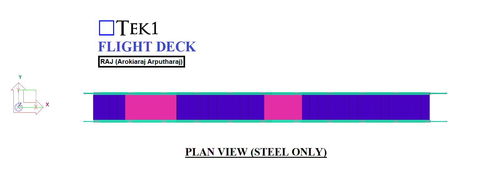
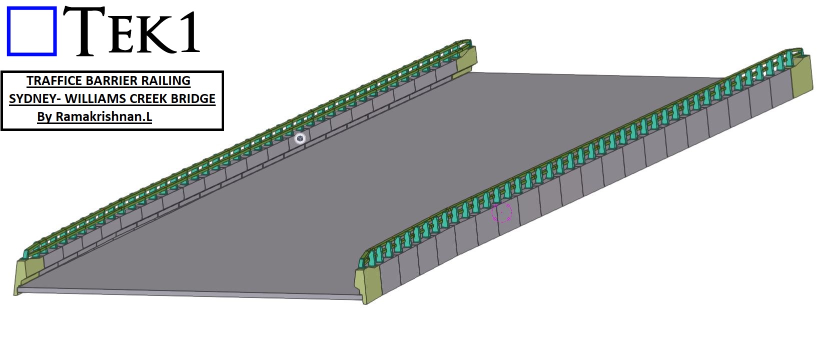
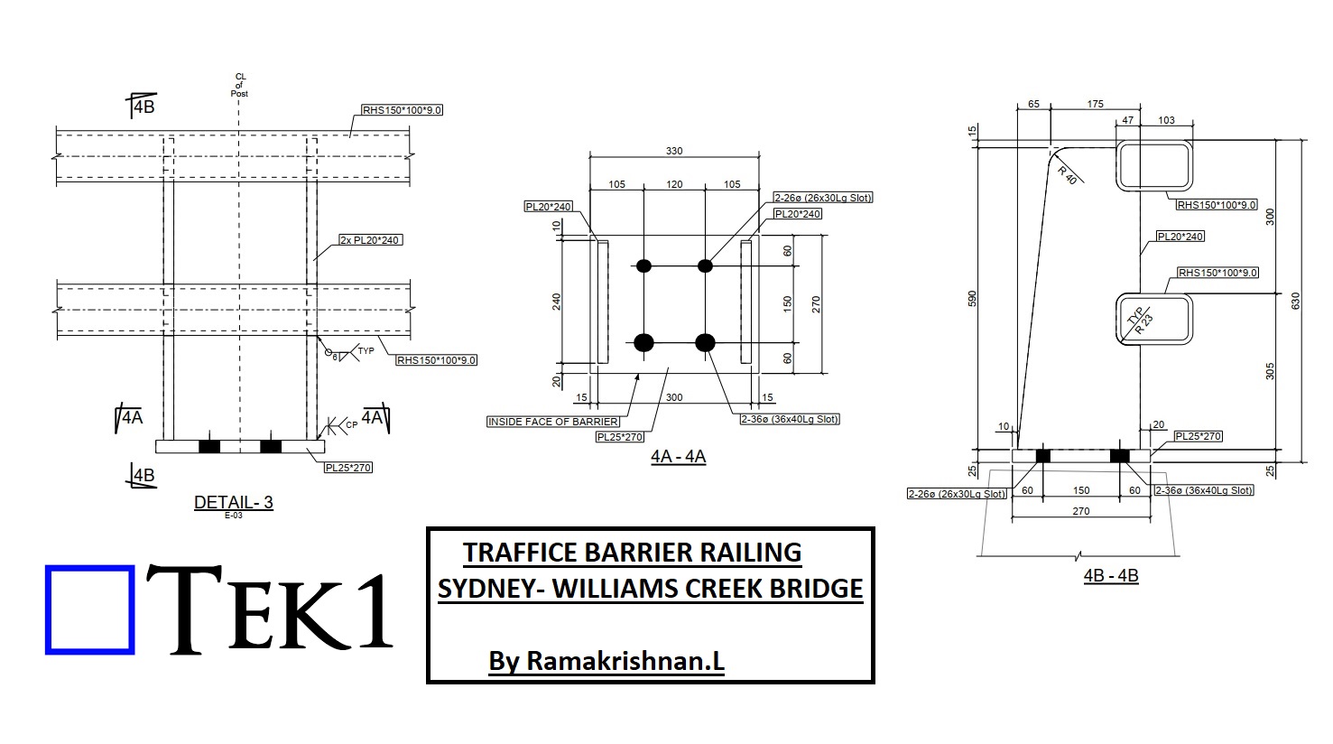
TEK1 recently completed the project TRAFFICE BARRIER RAILING project for the William Creek Bridge in Sydney. .
Project Overview
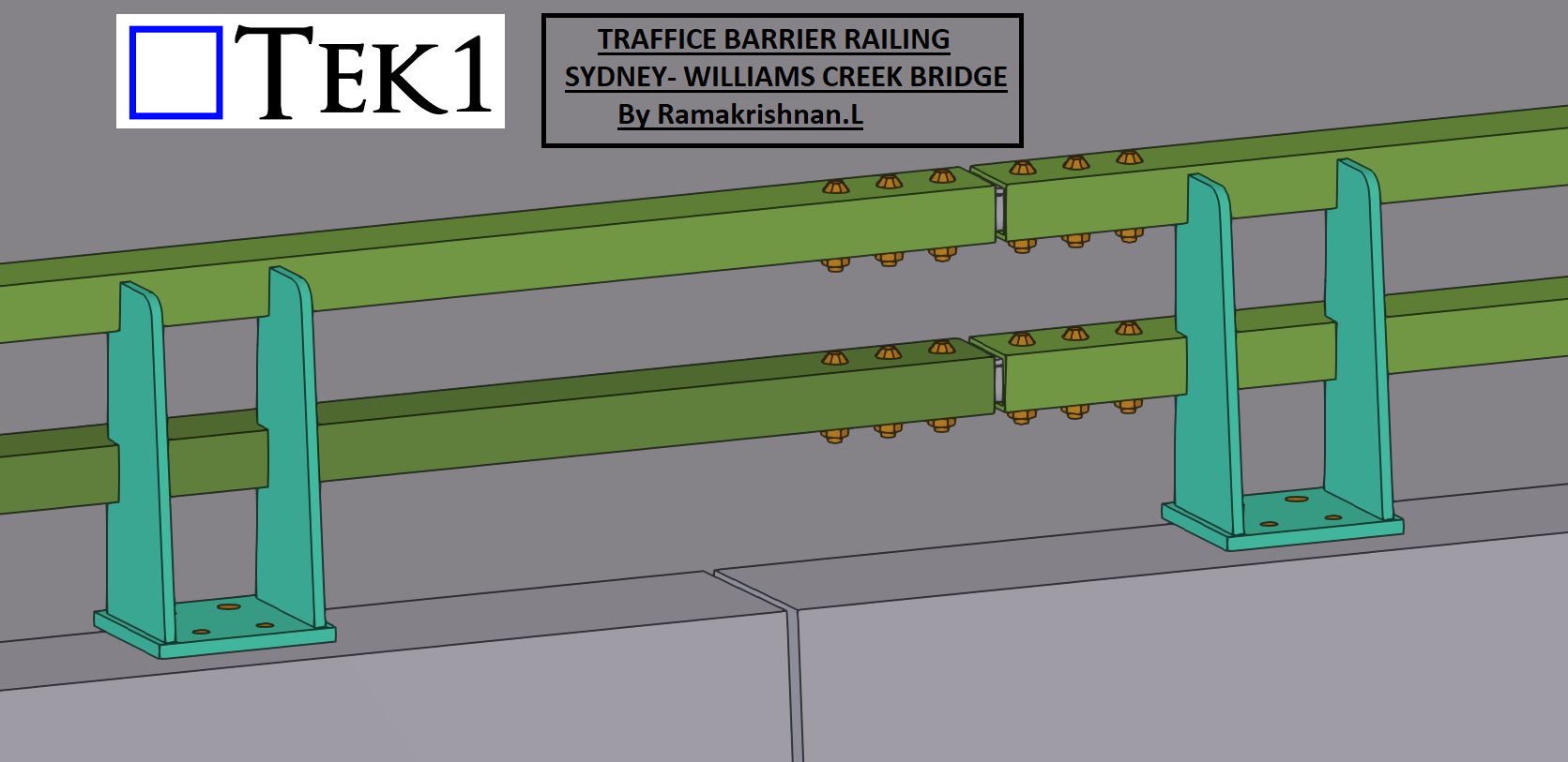
The primary focus of this project was the detailing and coordination of the barrier railing connections with respect to the precast barrier. These connections are integral to ensuring the railing system’s strength, stability, and compliance with safety standards.
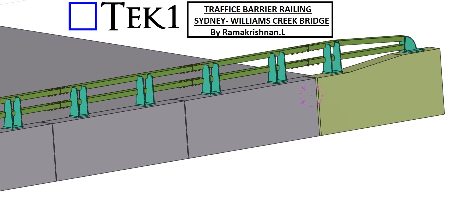
Key Features of the Railing Connections
Conclusion
TEK1’s work on the William Creek Bridge reflects our commitment to enhancing public infrastructure through precision detailing. By focusing on both safety and functionality, we’ve delivered a barrier railing system that meets the highest standards.
Stay tuned for more updates as we continue to contribute to impactful projects that make a difference in our communities.
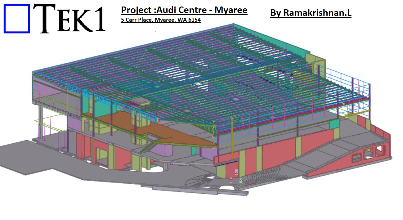
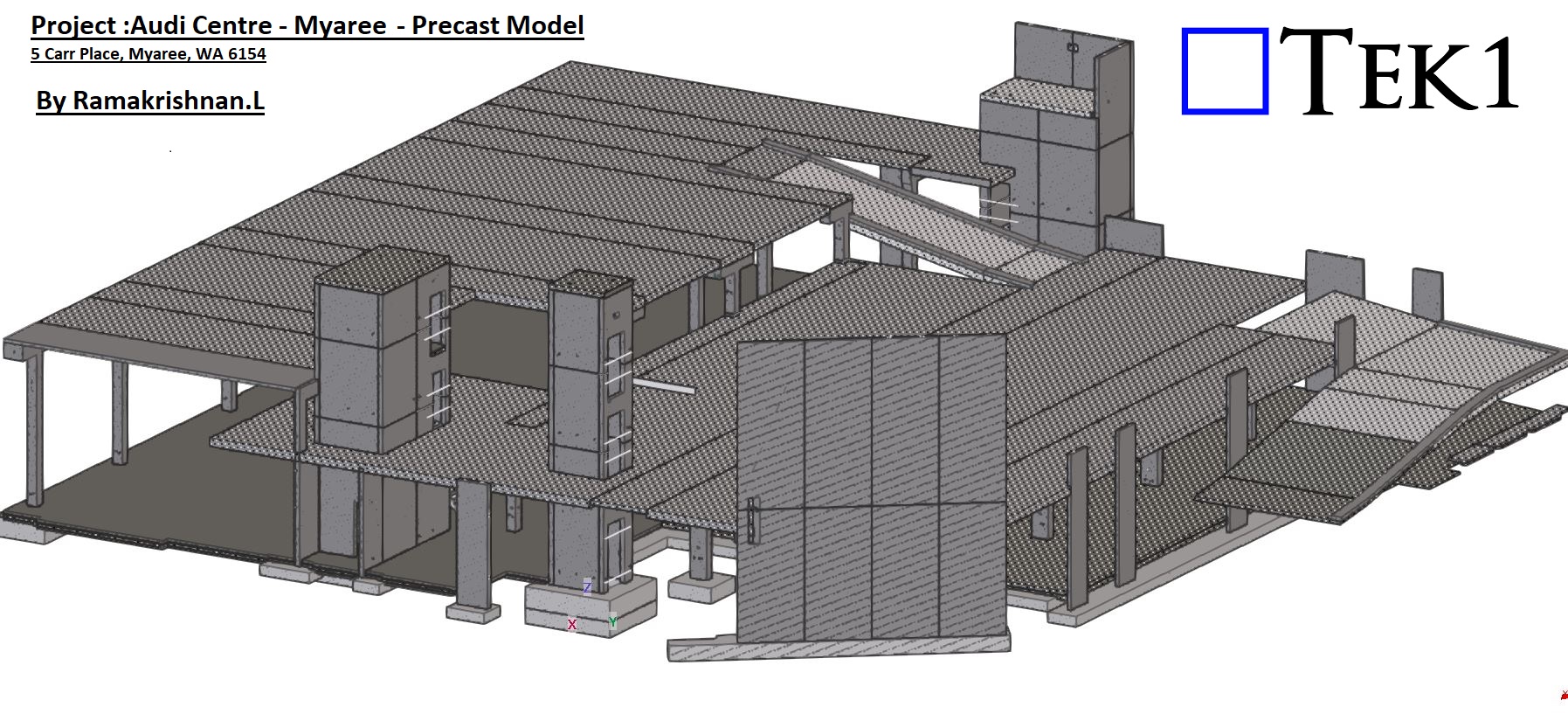
5 Carr Place, Myaree, WA 6154
TEK1 recently completed the project Audi Centre Myaree a Audi Car showroom in Western Australia. This impressive structure is a 100-tonne steel building, featuring two floors and a main roof, exemplifying modern design and engineering precision.
Scope of Work: Steel and Precast Panels
Our scope for this project included detailing both steel and precast panels. Managing these two critical elements simultaneously required meticulous coordination and attention to detail. The integration of steel and precast detailing enabled us to ensure accurate connections between the two systems, delivering a seamless result.
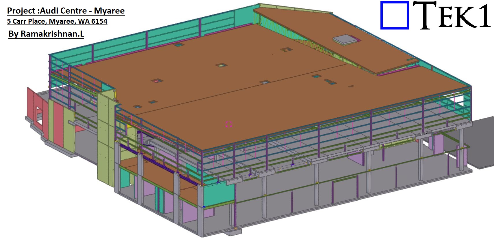
Overcoming Challenges with Precision
Handling both steel and precast in a single project can often lead to coordination challenges. However, thanks to TEK1’s skilled team and advanced detailing processes, we completed the project without any hitches. Our approach ensured that all connections were detailed precisely, aligning perfectly with the design and site requirements.
Precast Model
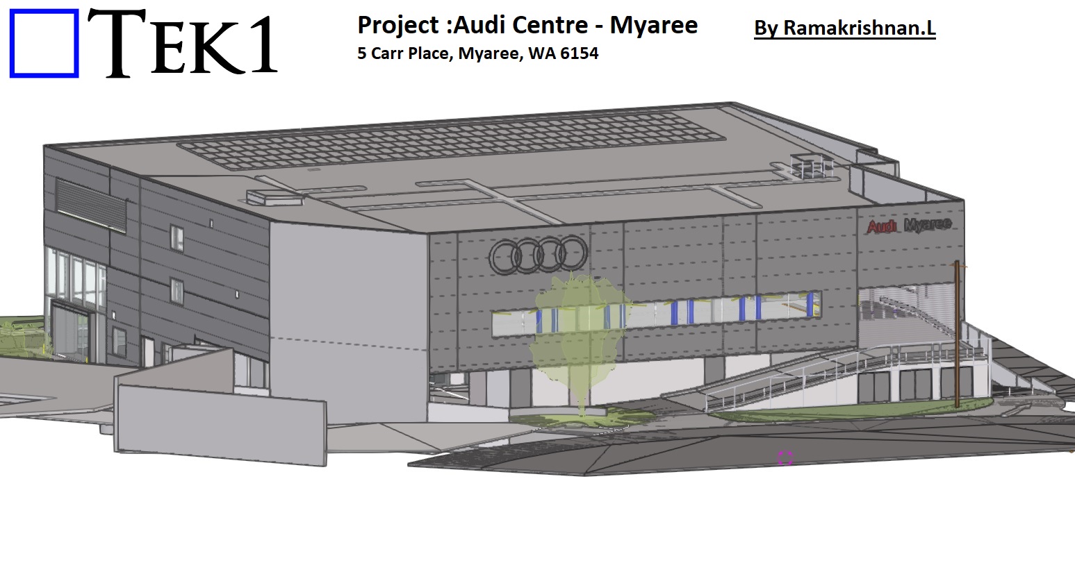
Conclusion: A Milestone in Steel Detailing
The Audi Centre Myaree stands as a testament to TEK1’s ability to manage complex projects involving multiple structural elements. By combining expertise, coordination, and a commitment to excellence, we delivered a showroom that reflects the high standards of the Audi brand.
At TEK1, we continue to set benchmarks in steel and precast detailing, ensuring that every project we undertake is marked by efficiency, accuracy, and success.
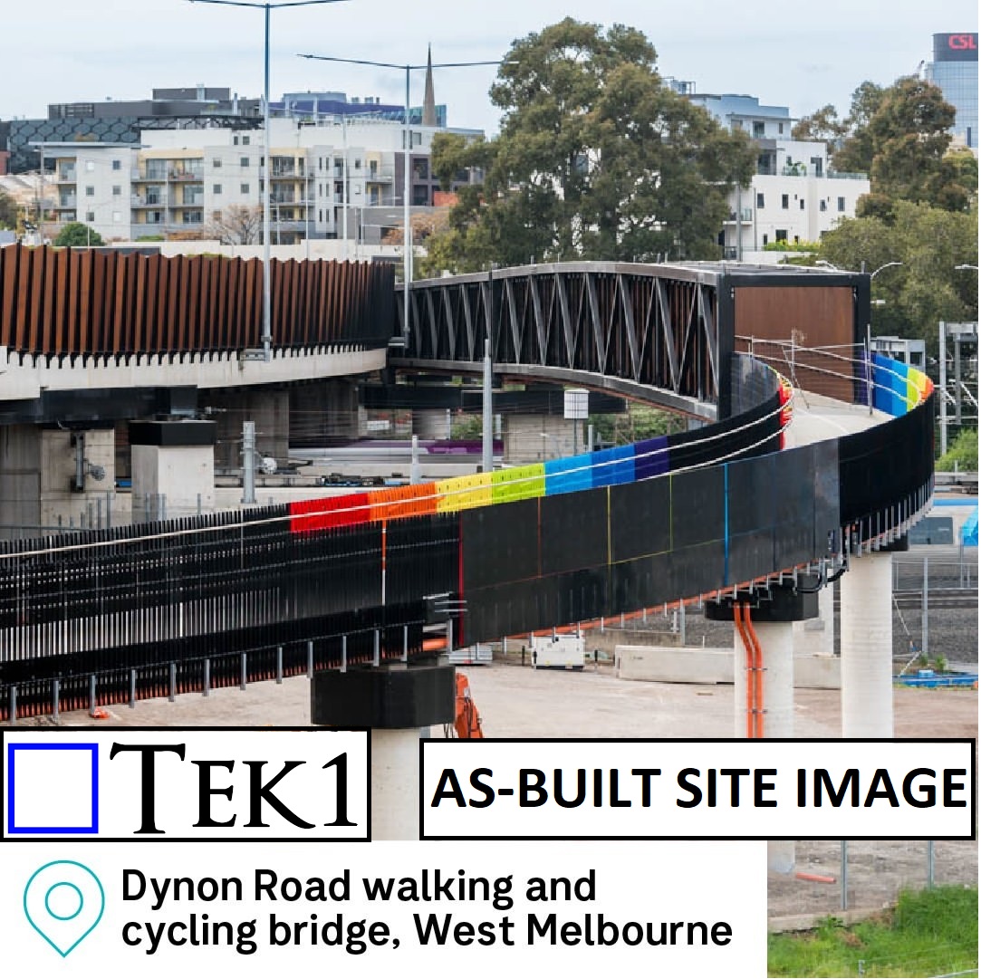
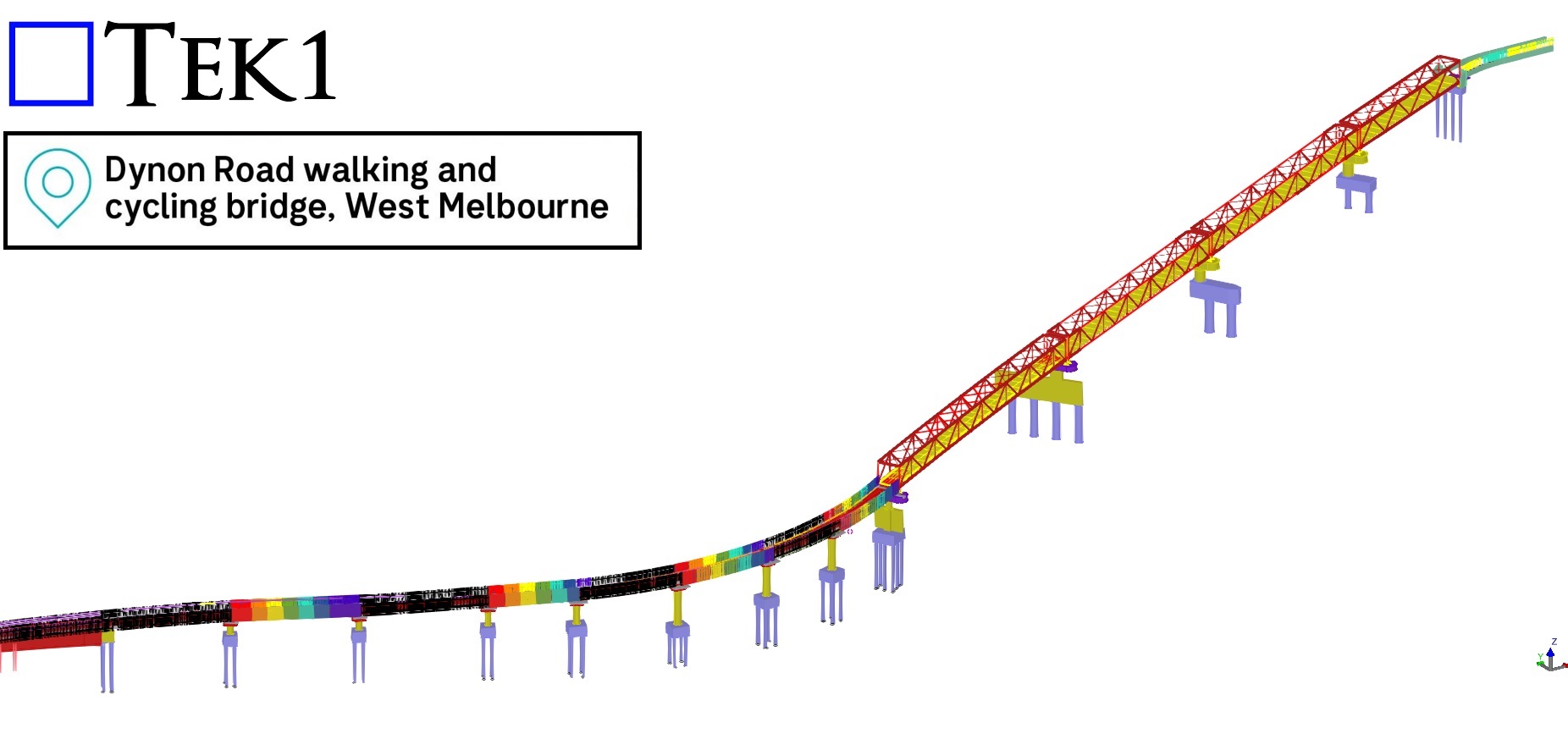
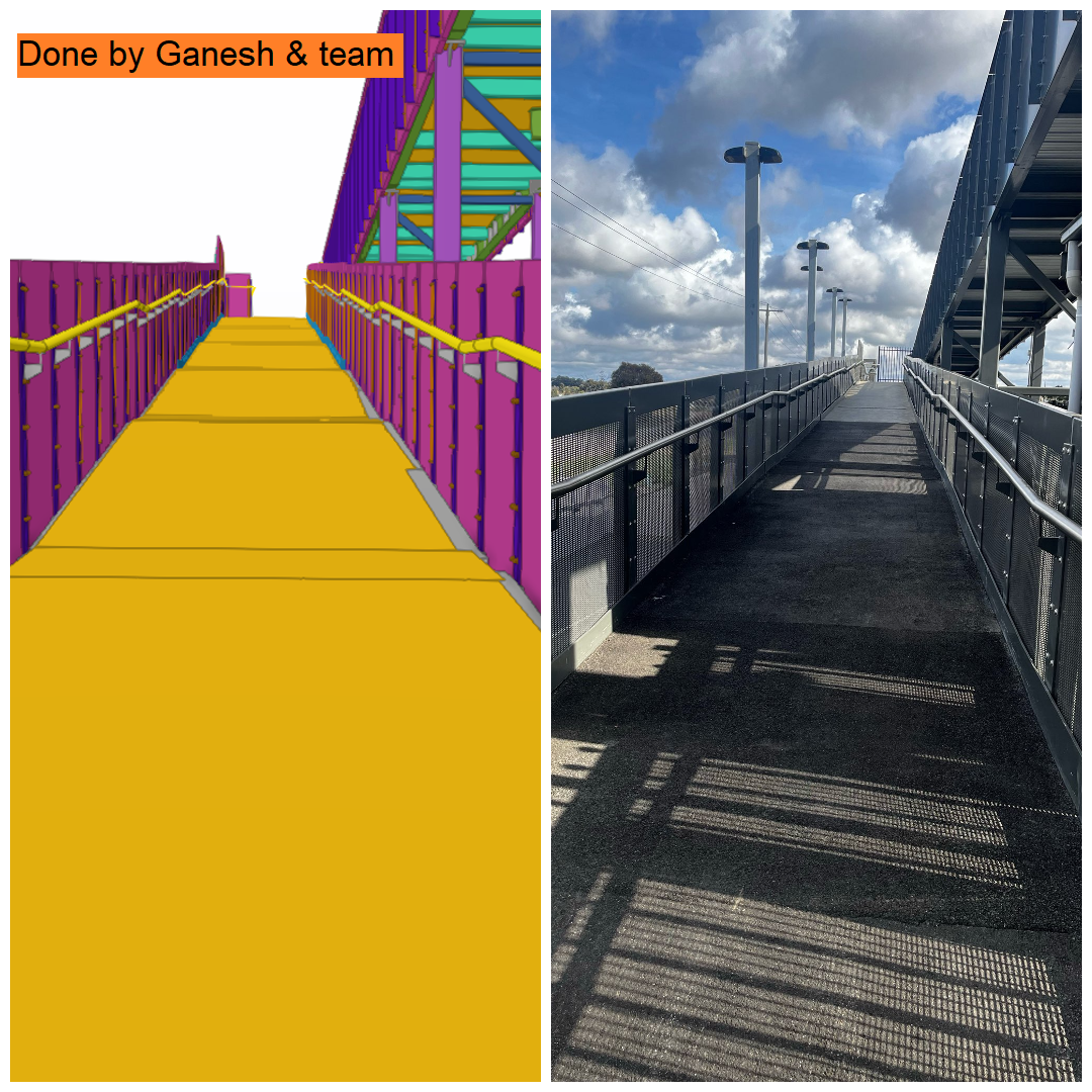
Workshop drawings for balustrades of Bridge#84 Dynon Road Walking & Cycling bridge, West Melbourne.
The fabrication drawings for the 230-meter-long balustrade panels, which feature vibrant, rainbow-colored finishes were delivered with NIL mistakes and on time.
Challenges in the As-Built Stage
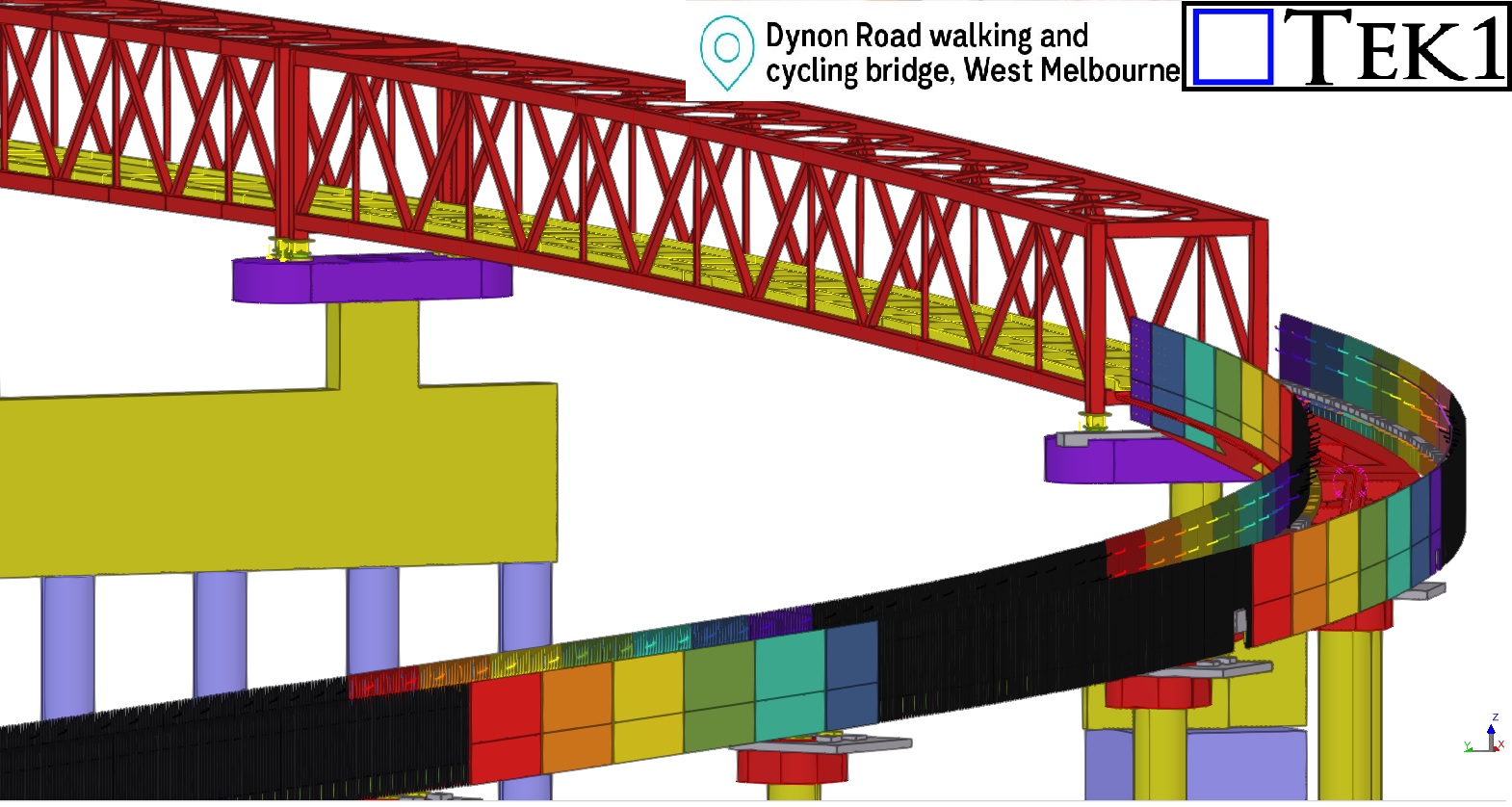
One of the most intriguing aspects of this project was the challenge posed by the as-built ramp slope and its curve, which deviated significantly from the original design coordinates. These deviations added a layer of complexity to detailing the balustrades, as each panel had to align perfectly with the precast kerbs.
To address this, we worked closely with the builder and requested precise site measurements. These measurements were essential for us to adjust our detailing to account for the as-built ramp’s unique coordinates, ensuring every panel fit perfectly into place.
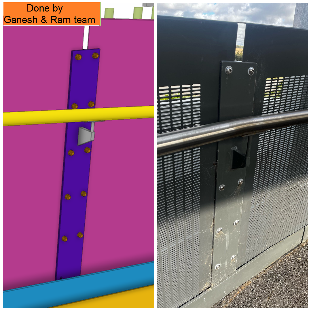
Tailored Solutions for On-Site Realities
The balustrade panels were fixed to the precast kerbs using as-built ferrules, demonstrating the adaptability required in projects where site conditions differ from the initial design. By leveraging the site measurements provided, we completed the detailing of all balustrades with precision, overcoming the complexities introduced by the ramp’s deviations.
Conclusion:
The Dynon Road Walking & Cycling Bridge is not just a pathway; it’s a vivid example of how meticulous detailing and innovative problem-solving can overcome challenges to deliver exceptional results. Its rainbow-colored balustrades are now a standout feature in West Melbourne, adding vibrancy and charm to the community.
Author: RAJ (Arokiaraj Arputharaj)
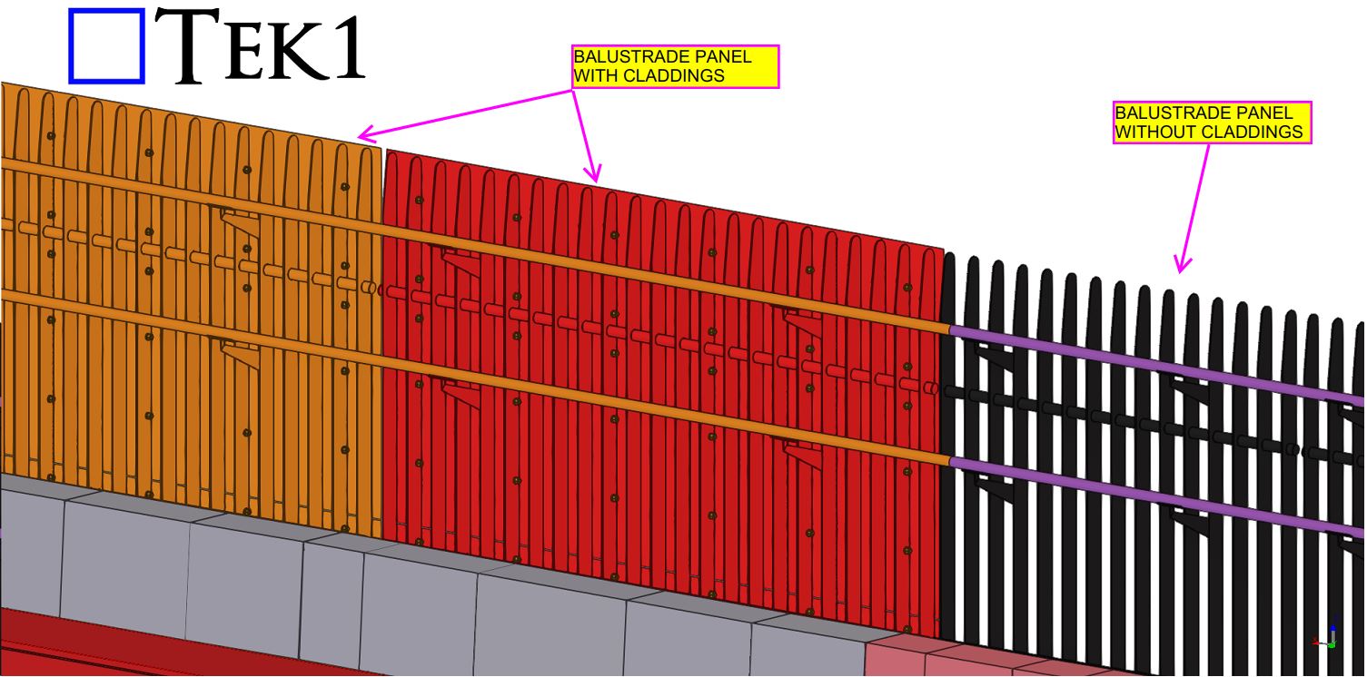
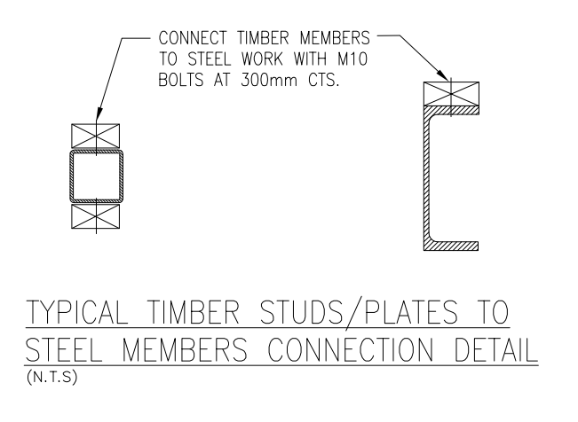
When it comes to construction projects, precision and adherence to design specifications are critical. However, sometimes, practical considerations highlight the need for adjustments to those specifications. One such scenario involves the fixing of a timber wall to steel SHS columns and beams, where the original design calls for M12 bolts spaced 300 mm on centers.
While the design specifies M12 bolts at 300 mm centers, this spacing is notably narrow for this type of application. Typically, such close spacing is reserved for situations where exceptional load-bearing capacity or additional structural support is required. In this context, a spacing of 600 mm on centers would be more than sufficient to secure the timber wall effectively, without compromising structural integrity.
The concern with the 300 mm spacing is not just overengineering but also the practical implications on the job site. Implementing such close spacing requires more materials, labor, and time, leading to increased costs and potential delays. Moreover, drilling excessive holes into steel SHS columns for fixing purposes could weaken the structural integrity of the columns, which is an outcome that must be avoided.
Given that the primary objective is to secure the timber wall to the steel structure, an alternative approach could be considered. Gun-fixing the timber studs directly onto the steel columns, without the need for drilled holes, is a viable option. This method is not only faster but also maintains the strength of the steel columns by avoiding unnecessary perforations.
Before proceeding with the job, it is essential to address this issue through a Request for Information (RFI). An RFI will formally document the concern regarding the overly narrow bolt spacing and propose the alternative method of gun-fixing. By raising an RFI, the project team can seek clarification and approval from the design engineers or the client to adjust the specifications accordingly.
This step ensures that all parties are aligned, and any modifications to the original design are officially approved, reducing the risk of rework or disputes later in the project. It also demonstrates due diligence and a commitment to delivering a project that is both cost-effective and structurally sound.
In summary, while the original design calls for M12 bolts at 300 mm on centers to fix the timber wall to steel SHS columns and beams, this spacing is unnecessarily narrow. A 600 mm spacing would be sufficient, and an alternative method of gun-fixing the studs to the columns should be considered. Before commencing work, this issue must be addressed via an RFI to ensure that all stakeholders are in agreement and that the project proceeds smoothly and efficiently.
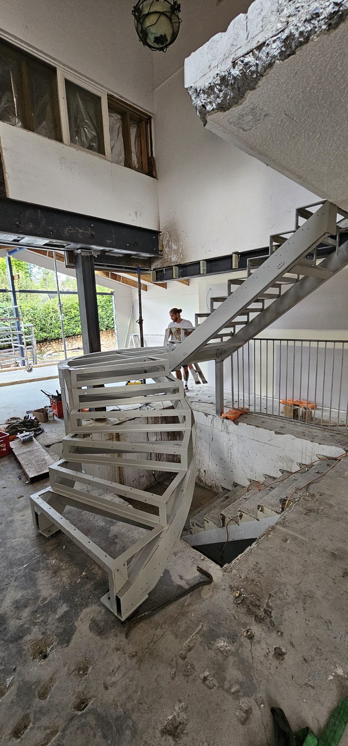
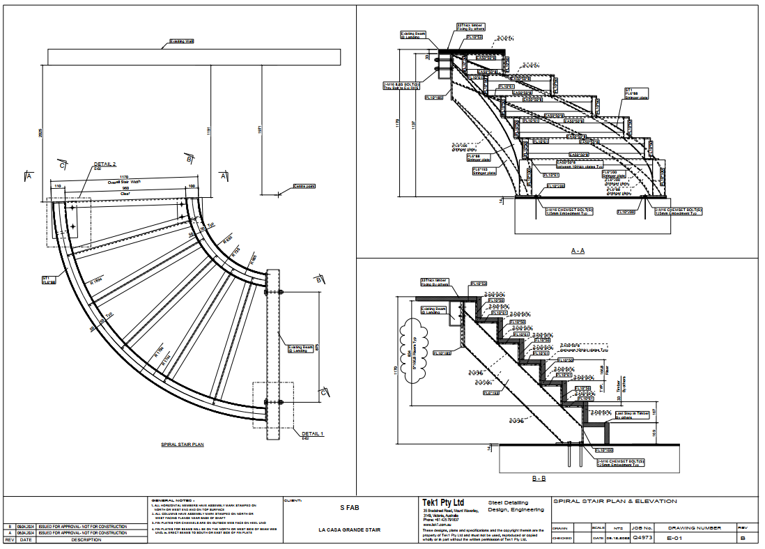
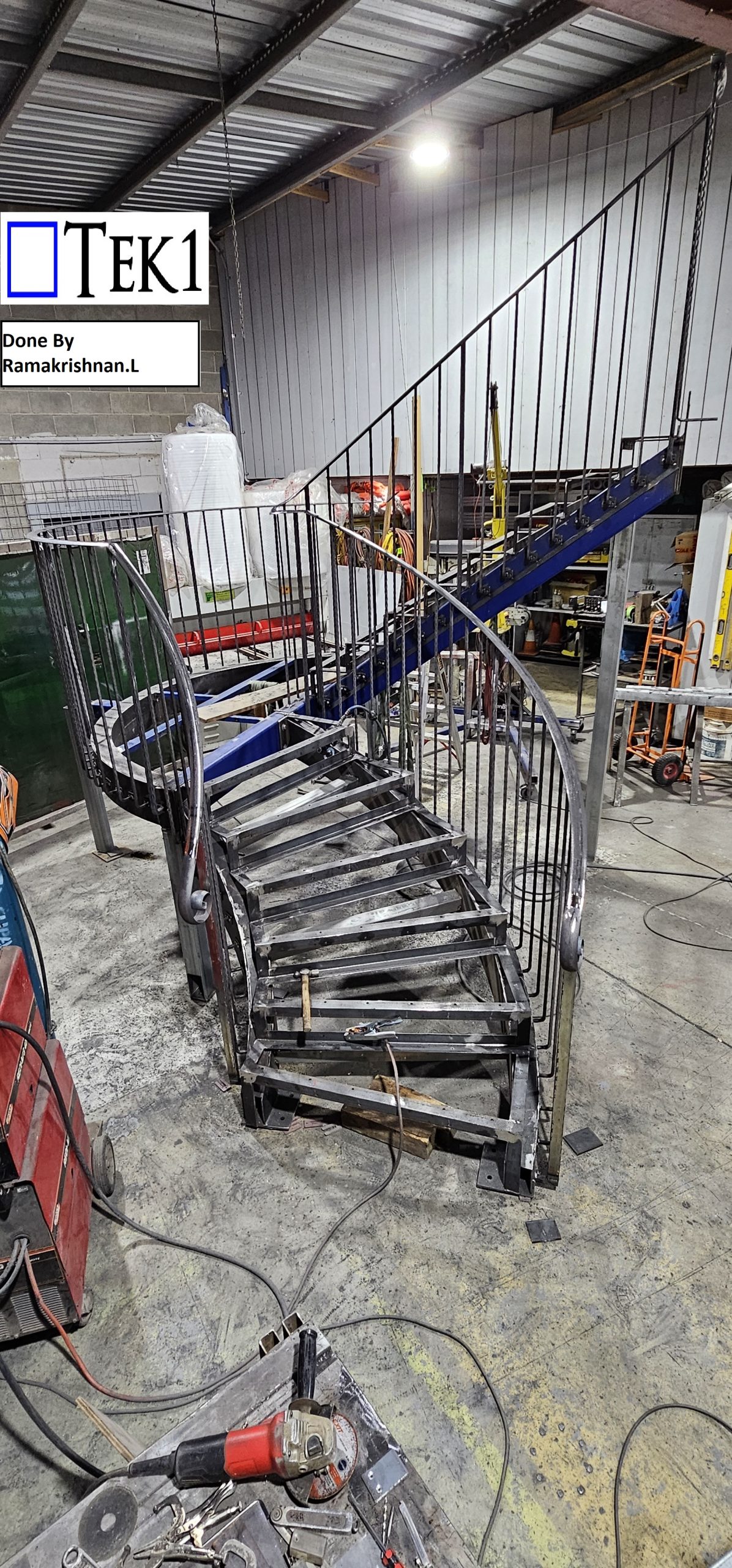
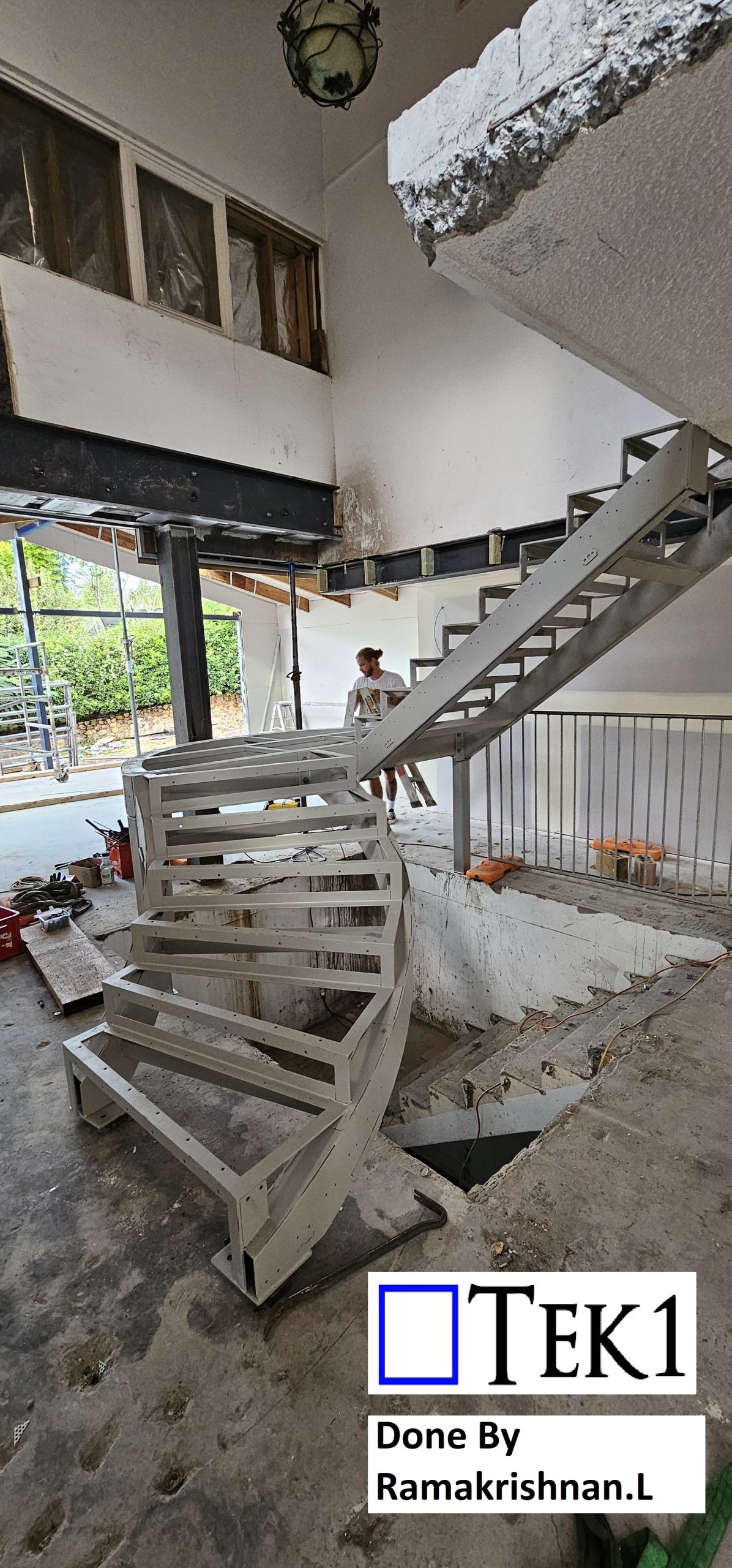
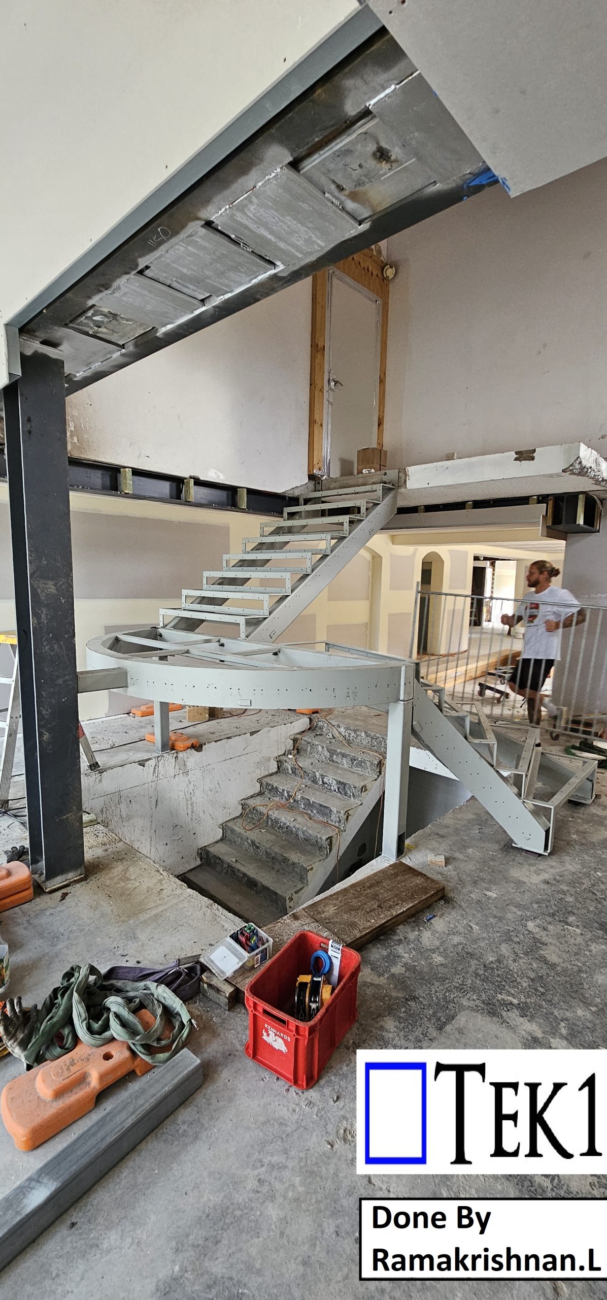
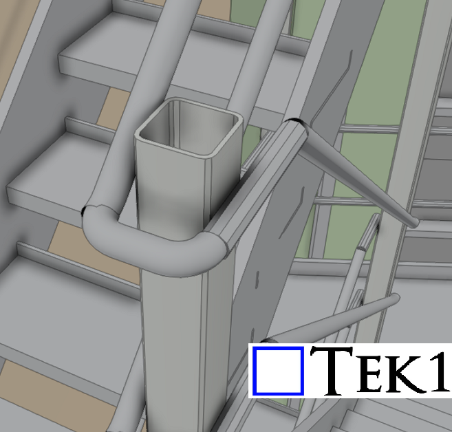
We are pleased to inform you that TEK1 has accepted the task of detailing the spiral plate-formed RHS stringer stair as requested by our client. Our team is well-equipped to handle this design, ensuring that all details meet the highest standards.
At TEK1, we have consistently provided top-notch miscellaneous steel detailing services to our esteemed clients, adhering to all relevant codes and standards. We are committed to delivering precise and reliable shop drawings tailored to your needs.
Should you have any queries related to miscellaneous steel shop drawings, please do not hesitate to contact us. We will promptly provide you with the necessary answers and support.
For any steel shop drawings you require for an ongoing project, feel free to reach out to Koshy at (03) 9560 6397 or +61 3 9560 6397.

Author: RAJ (Arokiaraj Arputharaj)
When this happens, it is ESSENTIAL that you call the client before you put in your variation documentation.
Why?
What should I do instead?
In the realm of steel detailing, it’s not enough to simply follow design drawings and IFC models. As detailers, a thorough understanding of general standards is crucial to ensure accuracy and compliance.
The Importance of Standards
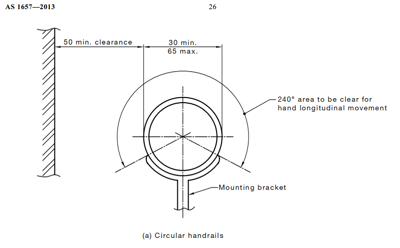
For instance, consider the Australian stair standards AS1657, which require a clear handrail area of 240° with a minimum clearance of 50mm. In the example below, the designer overlooked this standard, focusing solely on structural aspects without accounting for necessary clearances.
Identifying and Addressing Errors
As detailers, it is our responsibility to identify such discrepancies. In this case, the handrail does not meet the required clearance standards, which could lead to safety issues and non-compliance.
When we encounter designs that do not meet standards, it’s essential to raise queries with the client. This proactive approach ensures:
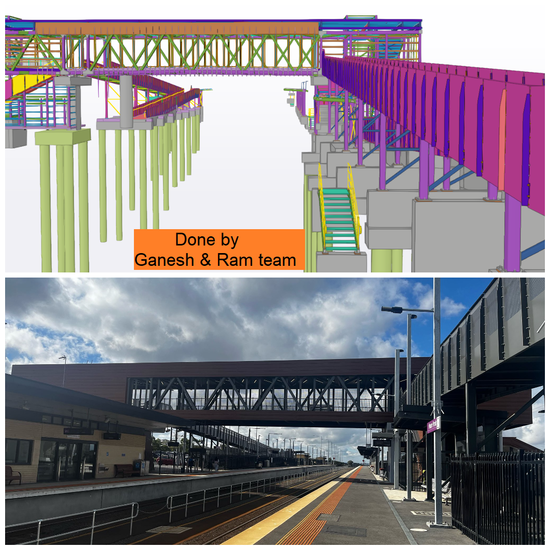
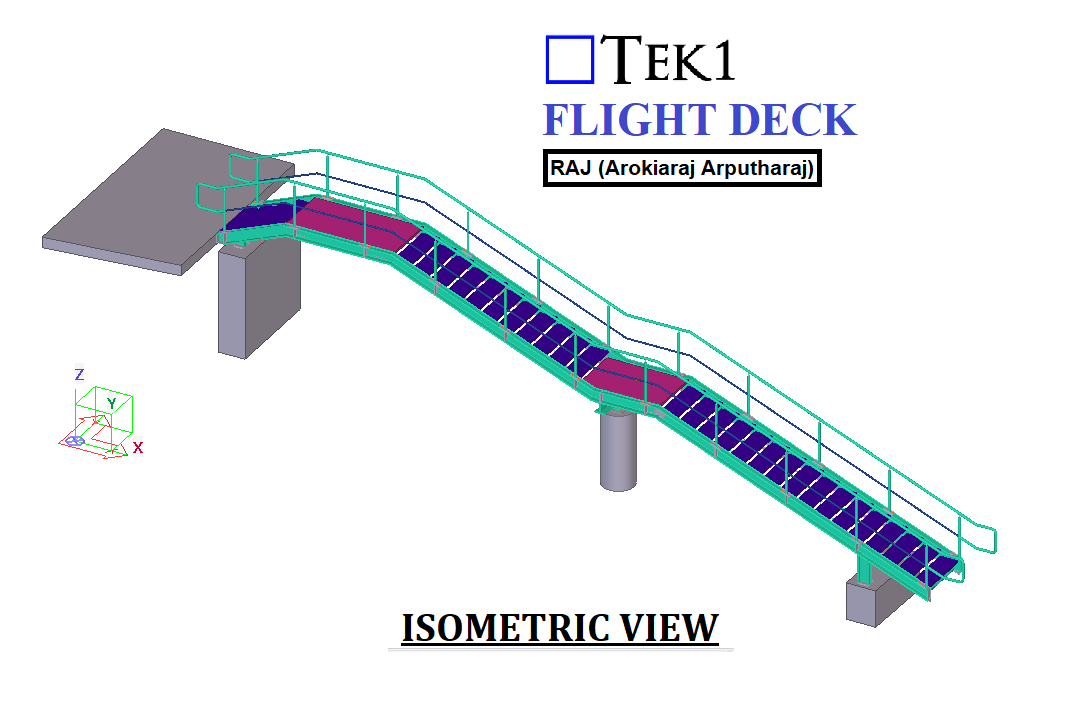
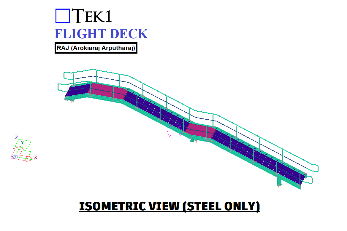
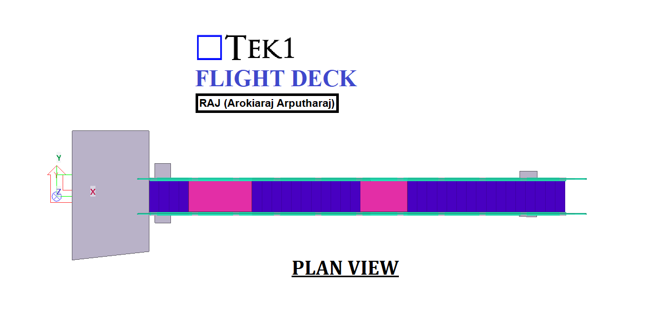
There’s nothing more satisfying than seeing our projects come to life. Witnessing the tangible results of our hard work, creativity, and meticulous planning fills us with immense pride and happiness.
From Design to Reality
Every project begins as a vision from our clients. Through detailed planning and precision engineering, we transform these concepts into reality. Overcoming challenges and refining designs, we ensure every detail meets our client’s expectations.
The Moment of Realization
Seeing a project transition from a digital model to a physical structure is magical. It’s when the abstract becomes concrete, validating our hard work and dedication.
Why It Matters
At TEK1, creating lasting and impactful structures is our passion. Seeing our projects come to life is a constant reminder of why we do what we do.