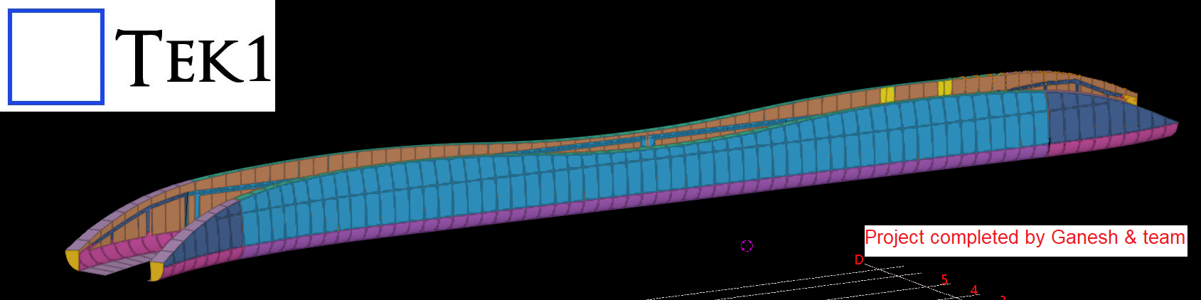
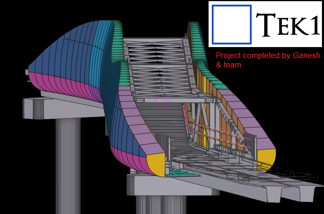
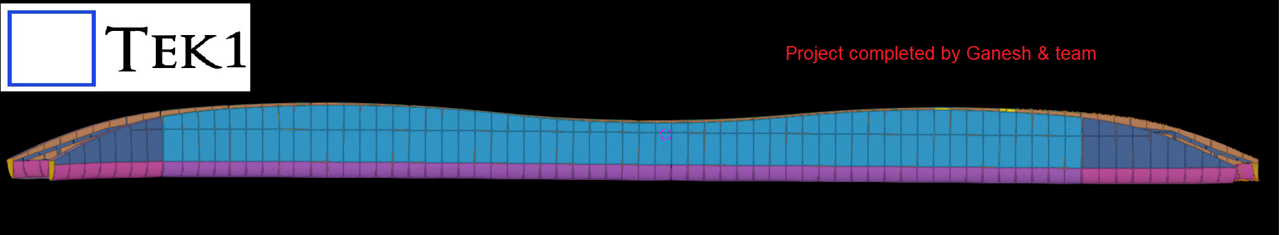
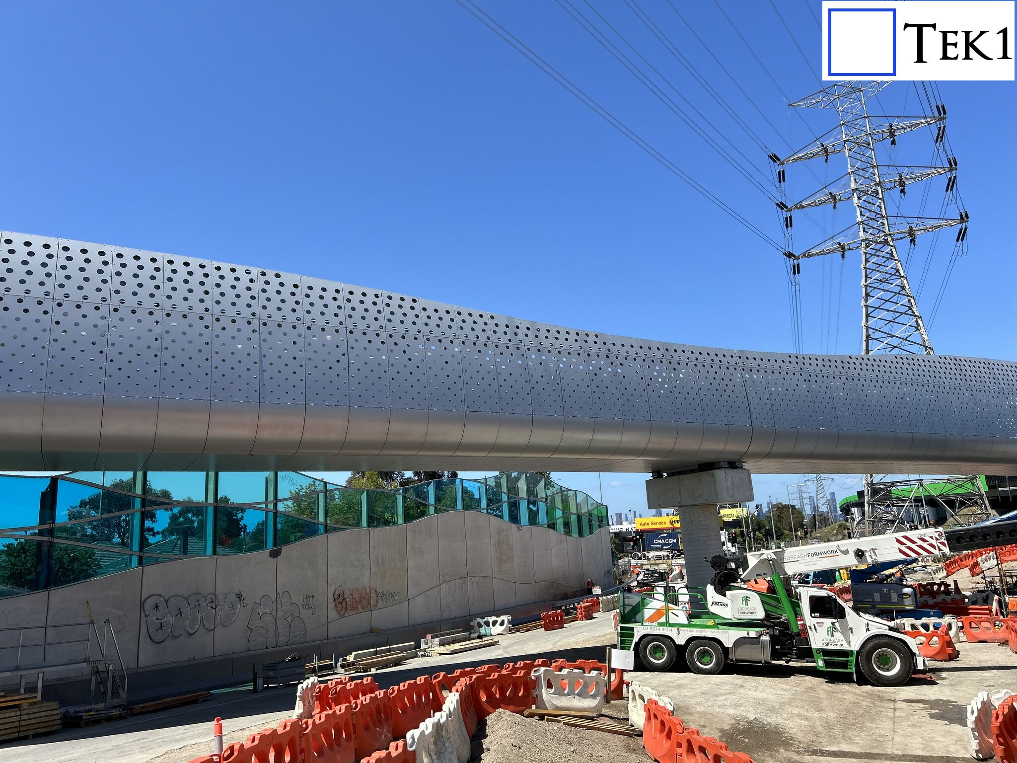
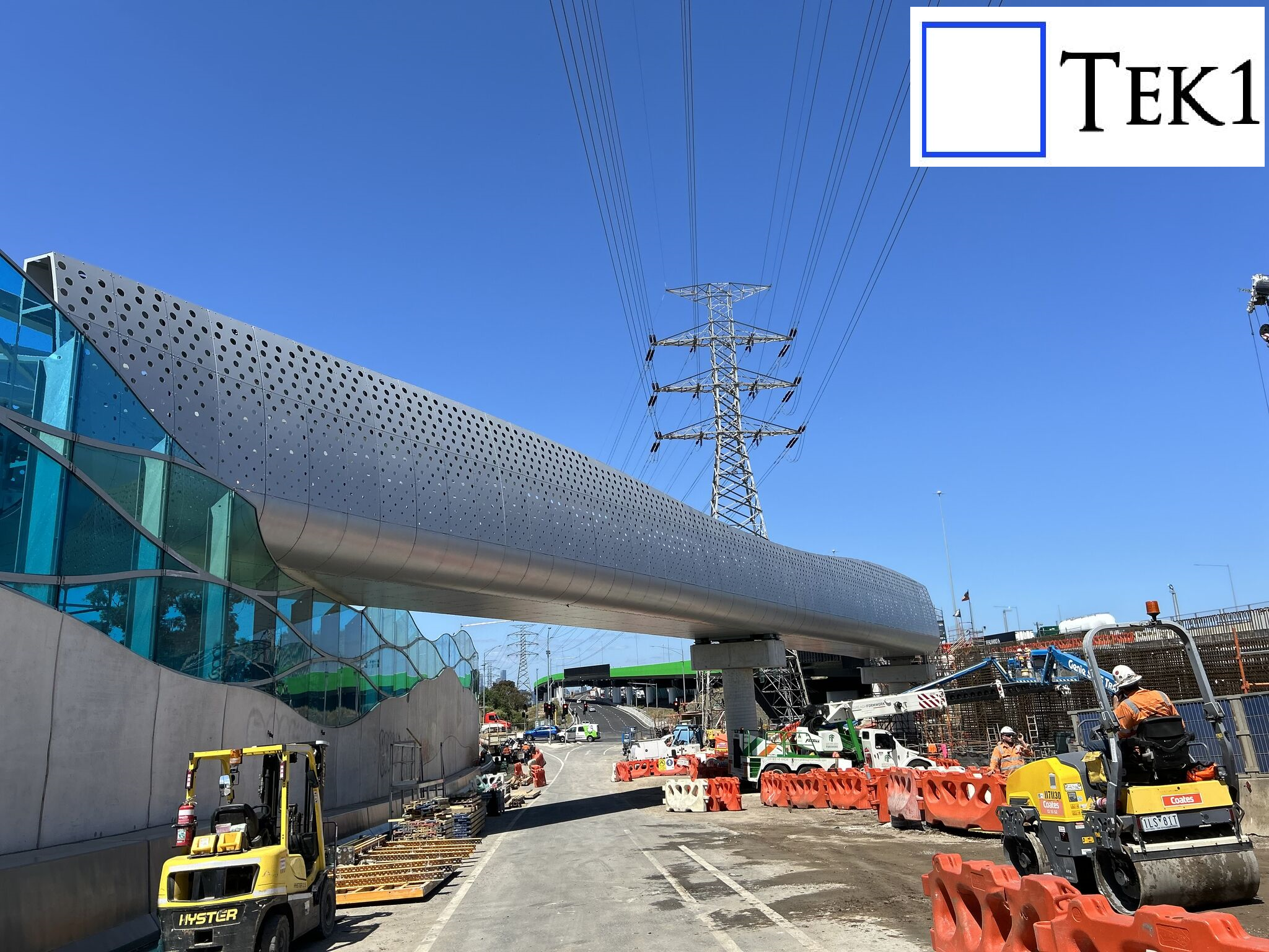
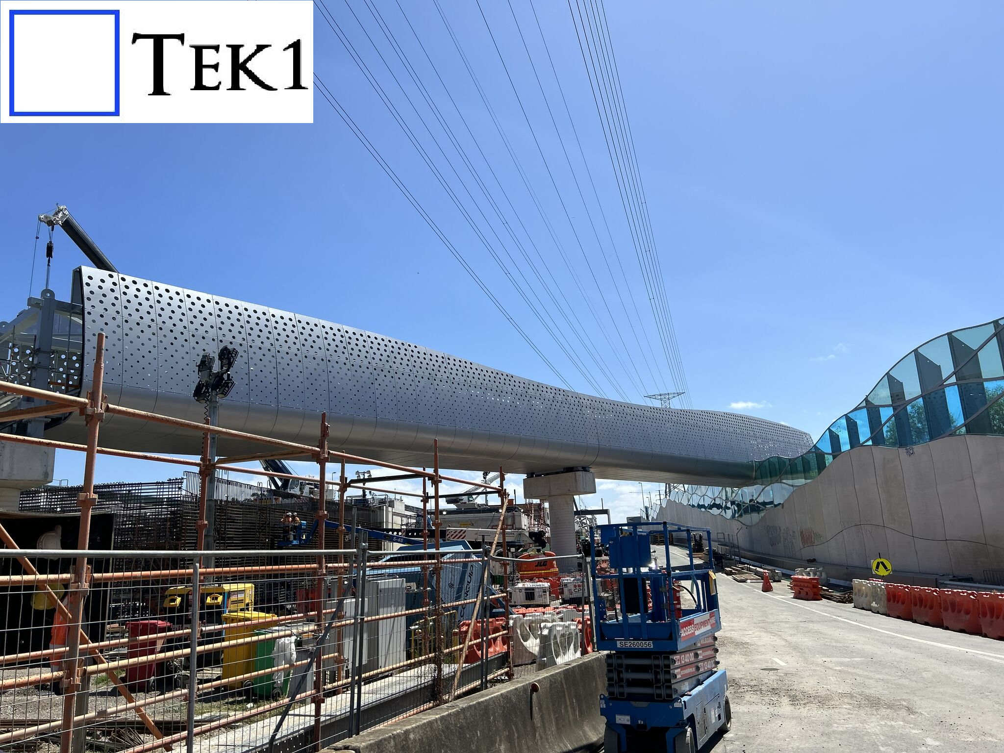
Tek1 recently completed a cladding project for a prominent organization in Australia. The project involved detailing cladding and its support system around a footbridge with unique challenges.
The footbridge featured curved ends, but these were not simple linear curves, making the design and detailing process particularly intricate.
Tek1 conducted numerous meetings with the client and engineers to finalize the cladding’s shape and ensure it met both aesthetic and structural requirements. This collaborative approach ensured the project’s success.
We hope you found our previous blogs on the Sydney Metro project insightful. If you missed them, check them out.
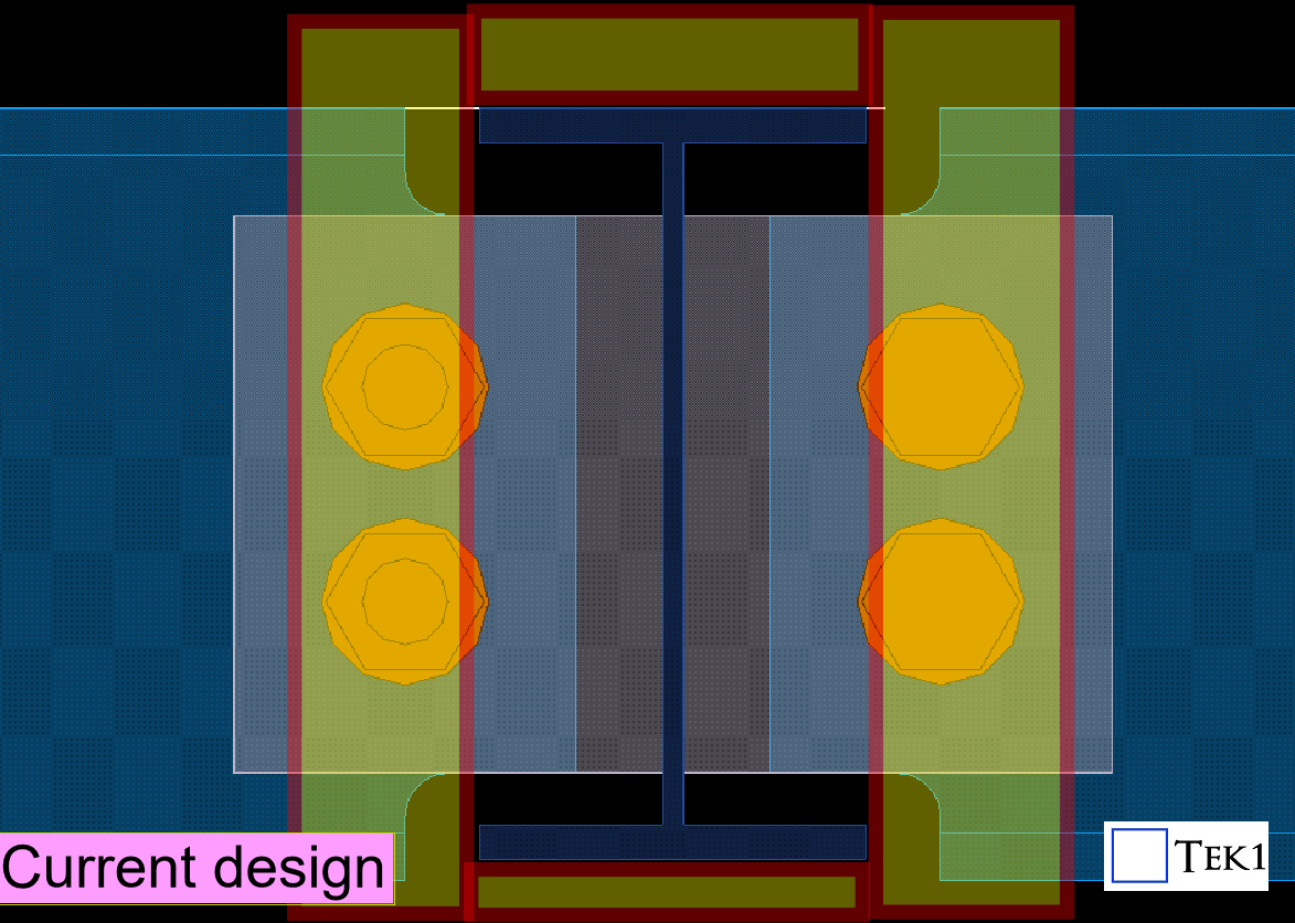
In this blog, I’d like to share another connection detail we proposed to the structural engineer on the Sydney Metro project
Since this is a metro project, fireproofing sheets are required on steel members as per the structural engineer’s specifications. However, the original connection details provided by the engineer were not feasible interms of installation of fireproofing sheets — they would make installing the fireproofing sheets difficult and time-consuming.
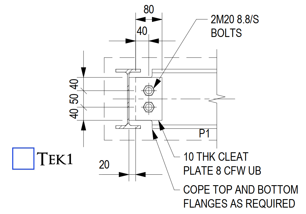
Please see the connection details below. These are the standard connection details typically used for the steel members.
However, applying these as-is may create difficulties during the installation of the fireproofing sheets.
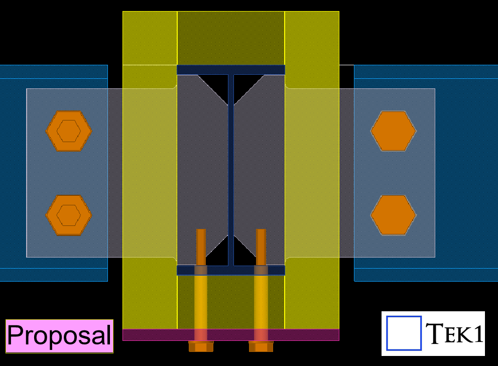
We identified this issue early in the detailing stage and proposed alternate connection details that would allow easier installation of the fireproofing sheets without compromising the structural requirement.
The engineer reviewed our proposal, suggested a few adjustments like thickness changes, and then approved our updated connection details.
Catching these issues early during detailing avoids major headaches later for installers and saves valuable time on-site
Stay with TEK1 for more updates on this sydney metro project
“Experience is the best teacher — but only if we learn from it.”
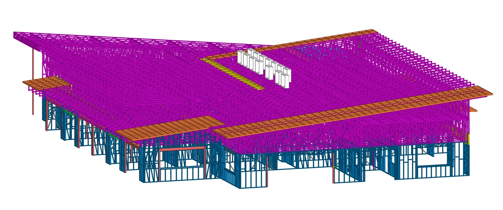
🧠 1. Frame Size Matters – Don’t Overlook Transport Constraints
Truss heights hit up to 3m and lengths extended to 10m – something that could change based on client and transport feasibility.
Wall frames also touched 3m in height and 5m in length – be sure to check if it fits the truck before detailing.
Roof overhangs? Review them early to ensure they’re compatible with transport or you’ll risk on-site chaos.
✅ Tip: Always check transport feasibility during quoting and in RFI#1
✂️ 2. Splitting Tall Walls – Think Before You Frame
External walls taller than 3m should be split during design.
Confirm site handling options – are cranes available, or will it be lifted manually?
⚠️ Don’t assume! Discuss early to avoid rework and surprises on-site.
🧩 3. Design Features for Roof Panels & Coordination with MEP for Wall Cutouts 🛁
Before locking in the wall layout, always confirm plumbing cutouts and vent pipe locations with the client, especially in WET areas.
If these aren’t aligned early, it can cause major trouble onsite — including last-minute frame cutting.
For Roof Frame like overhangs:
Rafters should be designed as doublers (to add strength).
Rafters must be perpendicular to the wall.
Noggings should run parallel to maintain overhang stability and simplify installation.
🔍 These small details make a big difference for smooth execution.
🚛 4. Confirm Transport & Lifting Method Early
Every frame size should be checked for transport in RFI#1.
Clarify lifting access – Is there a crane or only manpower?
🏗️ 5. Large Trusses – Assess or Be Stressed
For long trusses that might need splitting:
Evaluate engineering requirements early – if a truss fails, it’s not on us, it’s an engineering issue.
Consider onsite assembly time, weight, and transport limitations in your quote.
Flag “suspect trusses” during quoting with buffer for iterations.
🧠 Smart Detailing = Fewer Site Surprises
📄 6. Quote Smart – Define Scope Clearly
Don’t quote blind. Wait for all necessary drawings and details.
Add buffer for unknowns and clarifications.
Clearly state we follow the provided architectural and structural drawings. If things change later — that’s a variation.
🔄 7. Variation Handling – Get it in Writing
Raise a variation immediately for any change that occurs after quoting.
Pause all work on the affected section until written client approval is received (or the variation is rejected).
If there’s a delay — pick up the phone and speak directly with the client. Clear communication is key to minimizing disruptions.
To alert the client that a change has happened, and that there is a delay in the program.
Remember:
“Nothing speaks louder than an invoice and documented delay.”
💡 8. Our Design Suggestions – Add Value and Help Your Client Cut Costs
If we propose design improvements (e.g., optimizing the LGS frame layout), they should be quoted as added value.
When working off client-supplied drawings, and we identify missing details or unclear sections:
We can submit proposals for improvement.
If this was clarified in the quote, it is already within our scope — no need to raise it as a variation.
Smart detailing isn’t just about execution — it’s also about helping our clients save time and money.
🧱 9. Client-Driven Design Changes – That’s a Variation Too
Any change the client makes for ease of installation or cost saving must be quoted as a variation.
📋 LGS Project Checklist (for Detailers & PMs)
✔️ Confirm frame size limits (wall/truss) with client ✔️ Review transport feasibility and crane availability ✔️ Request complete architectural, structural, and MEP drawings ✔️ Identify special features (cutouts, splits, overhangs) early ✔️ Define scope clearly – design vs. detailing only ✔️ Include buffer time for potential RFI clarifications ✔️ Document all design and client-driven changes ✔️ Conduct internal reviews before client submission ✔️ Flag and assess suspect trusses during quoting
💬 Final Thoughts
Whether you’re a detailer, project manager, or fabricator, I hope this blog helps you:
Spot issues early
Avoid costly site changes
Deliver smoother, smarter LGS solutions
📢 More Coming Soon
We’ll continue sharing more real-world LGS insights, including:
🧠 “Can You Spot the Problem?” detailer challenges
🛠️ Cost-saving ideas we’ve implemented
Stay tuned — and let us know if there’s a specific LGS topic you’d like us to cover!
To explain the application and detailing requirements of temporary loose plate connections used in precast panel-to-panel joints. This document outlines the types of connections (parallel and corner), their structural purpose during erection, and their specific use in warehouse and multistorey buildings. It also highlights the importance of accurate detailing for cast-in ferrules and placement considerations to avoid clashes with structural elements like roof steel.
The plate connection used in Precast Panel to Panel connection depends on weight, wind, loading, and shape. The plate also contributes to the additional strength of the panels.
These connections are used after erection, as they are already structural connections at the panel bottom (grout tube with dowel bars), along with the brace connection. After that, an additional temporary plate is connected from panel to panel for extra strength.
THE LOOSE PLATE TYPE OF CONNECTION:
Panel to panel (Parallel).
Perpendicular panel with corner connection.
This type of connection is commonly used for panel-to-panel connections.
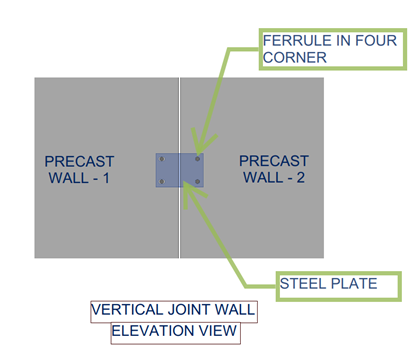
1.PANEL TO PANEL (PARALLEL):
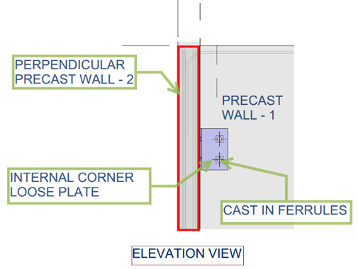
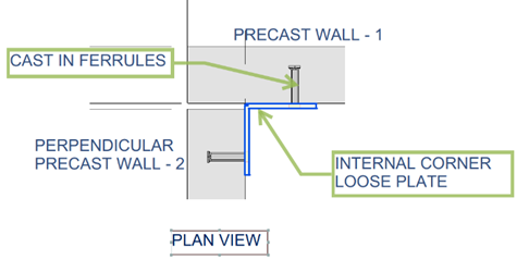
2.PERPENDICULAR PANEL TO PANEL CONNECTIONS AT CORNER JOINT
APPLICATIONS:
WAREHOUSE BUILDING CONDITION.
The panel-to-panel connection adds additional strength and also helps with propping.
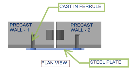
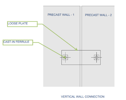
The loose plate connects to the panel surface with the help of cast-in ferrules.
This type of connection is mostly used in warehouse projects, and the plate is usually not removed after erection.
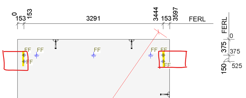
The detailer should provide exact locations with dimensions for cast-in ferrules. For example, refer to the drawing below.
This type of connection is placed inside the building to avoid affecting the exterior appearance.
MULTISTORE BUILDING.
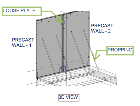
Basically, precast panel-to-panel connections involve steel loose plate connections to support the erection process. Mostly, this type of plate connection is temporary.
Once the precast wall is erected, the loose plate is connected to the cast-in ferrules with the support of propping.
Once panel erection is completed, the loose plate will be removed. The main reason for removing the plate is to achieve the panel finish.
This type of connection is placed inside the building to avoid affecting the exterior appearance.
NOTES:
Generally, position all precast connections below the roof steel to avoid clashes with any roof steel works. When placed above the roof steel, they may interfere with the installation or alignment of roof components.
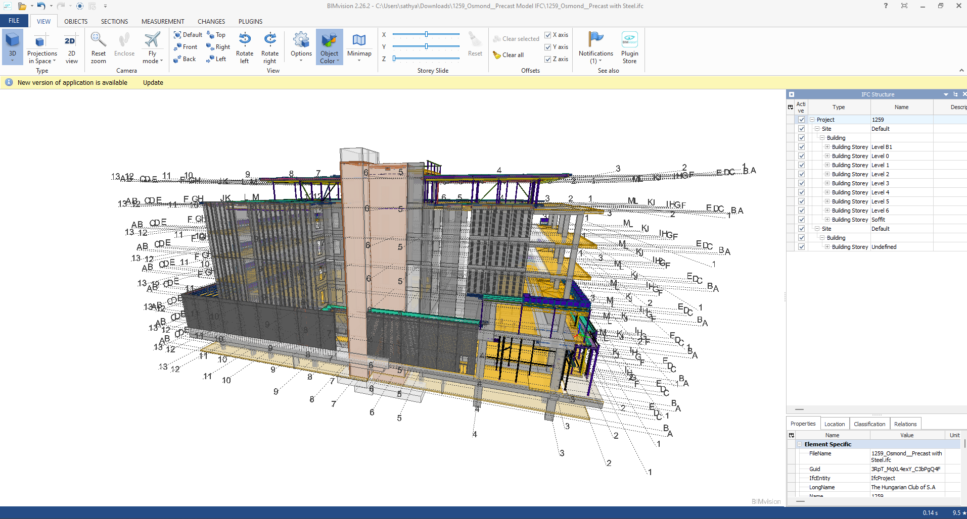
Industry Foundation Classes (IFC) is an open file format developed by Building Smart Alliance. It is an international data exchange standard for exchanging building information across different software platforms. An IFC Model is just a model of a building or a construction project with all geometric, structural, and semantic information.
Key Features of IFC Models:
Open Standard: IFC is vendor-independent, i.e., any software that supports it can be accessed, without regard for the vendor.
Static Data Exchange: It is mostly utilized for data exchange between software tools, data import, and export. For instance, an architect can create a model using Revit and export it as an IFC file, which can then be imported into structural engineering software like Tekla or SAP2000.
Limitation of Real-Time Coordination: IFC files are representations of the model at a specific moment. Changes in one application are not duplicated in another except where the file is re-exported and re-imported.
Use Cases:
Exchange of models between stakeholders with various software.
Ensuring interoperability in interdisciplinary projects (e.g., construction, engineering, and architecture).
Advantages of IFC Models:
Encourages collaboration and interoperability in BIM workflows.
Reduces errors by making sure all stakeholders are working from the same information.
Allows clash detection and coordination between different disciplines.
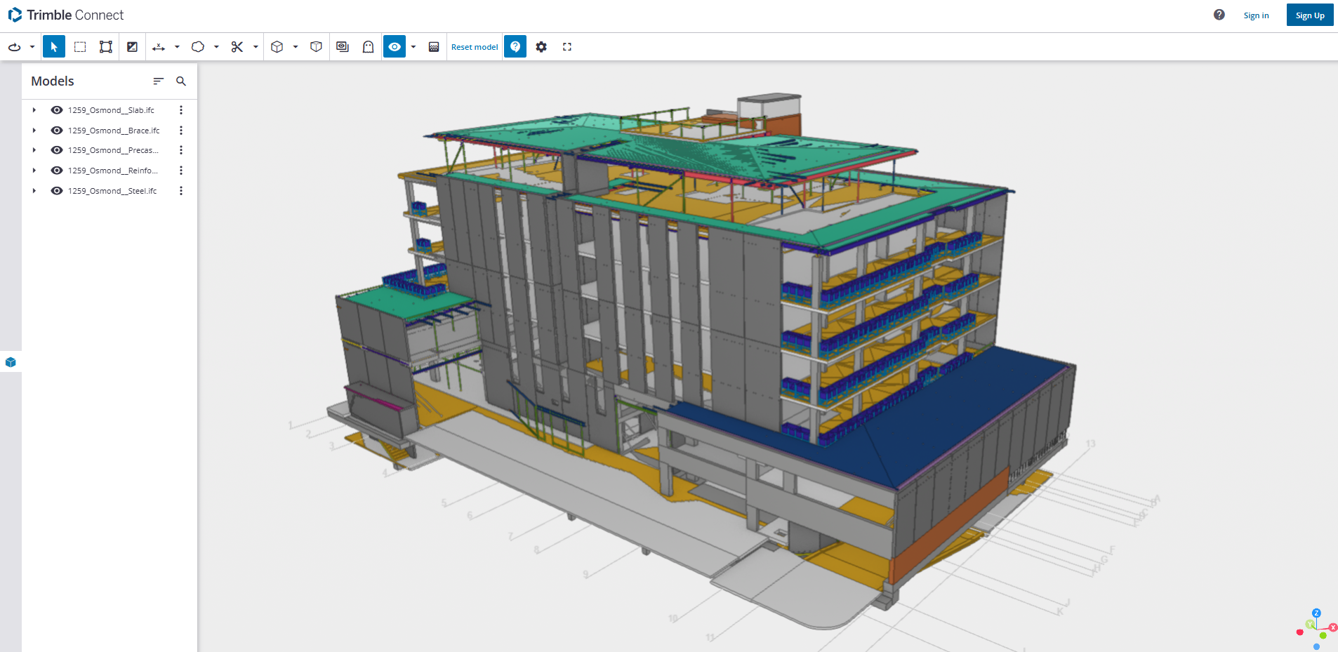
B. Live Link Model Viewer
A Live Link Model Viewer is software that enables real-time sharing and visualization of BIM models on various software platforms. Unlike IFC models, which are pre-exported static files, a Live Link Model Viewer enables multiple users to work on the same model at the same time using different software programs. Common examples of Live Link Model Viewers are:
Revit Live: A cloud-based collaboration platform by Autodesk.
Trimble Connect: A BIM data management and sharing tool.
Key Features of Live Link Model Viewers:
Real-Time Collaboration: One software application’s changes are reflected immediately in the model viewer and other linked applications.
Dynamic Data Sharing: Unlike static IFC files, Live Link Model Viewers offer dynamic, real-time linking between software applications.
Multi-User Collaboration: Multiple stakeholders can view and edit one model at the same time even though they are in different software.
Use Cases:
Real-time collaboration among architects, engineers, and contractors.
Collaborative design review and clash detection.
Smooth communication between teams working on different software platforms.
Advantages of Live Link Model Viewer Benefits:
Make collaboration more effective and faster.
Eliminate the need for repeated file imports and exports.
Enhance accuracy by getting the entire team to work on the current version of the model.
At TEK1, we believe great detailing is more than just precision—it’s about understanding real-world challenges and turning complexity into clarity.
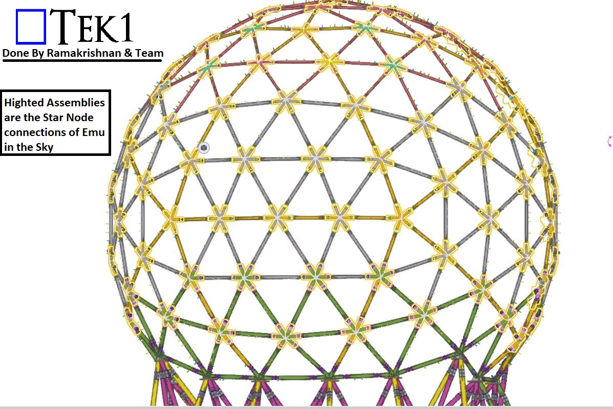
The Challenge
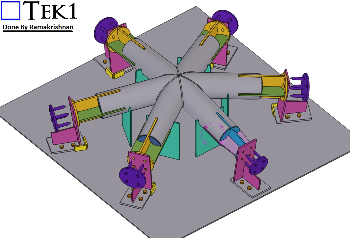
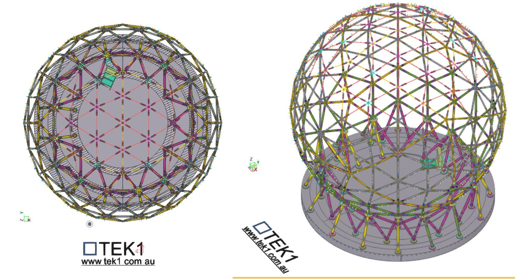
The Great EMU in the Sky project presented one of the most unique and technically demanding structures we’ve ever worked on—a 30-metre-wide globe made up of 128 intricate “star nodes” connecting the bracing members.
These nodes weren’t ordinary joints. Each featured 5 or 6 connection points and came in three different CHS sizes, with every arm set at unique, non-repeating angles.
For the fabrication team, this posed a significant challenge:
128 Complex Star Nodes, each with custom angles
Inconsistent geometries
Time-consuming and difficult to fabricate accurately
Even with precise 3D modelling, the practicality of fabrication was proving to be a serious bottleneck. Something had to change.
The Turning Point
That’s when TEK1 took the initiative.
Rather than simply delivering a model and walking away, we engaged directly with the fabricator to understand the issue from their perspective. We realized that even the most accurate detailing wasn’t enough—what the team needed was smarter, fabrication-friendly solutions.
The Solution
Our detailing team re-engineered how the star nodes were documented, presented, and ultimately fabricated. Key solutions included:
✅ Custom fabrication jig design: We developed a dedicated jig that allowed star nodes to be fabricated with greater ease and precision, regardless of the angle configuration.
✅ Standardized node sub-groups: We grouped similar nodes together to reduce variation and streamline production.
✅ Detailed templates: For common angle types, we provided accurate templates to guide fabrication.
✅ Visual fabrication aids: Clear drawings showing exact cuts, welds, and orientations for every node.
🤝 Stronger collaboration between design and workshop teams
Most importantly, the fabricators were able to work with confidence, knowing each node would come together exactly as intended.
Taking Detailing to the Next Level
This project reinforced one of TEK1’s core values: true excellence in detailing comes not just from precision—but from empathy. When we truly understand the needs of the people building the structure, we unlock practical, buildable solutions.
The Great EMU in the Sky is more than a globe—it’s a powerful example of what happens when detailers and fabricators work together as one team.
📢 Call to Action:
🚀 Have a complex structure or fabrication challenge? Partner with TEK1—where technical expertise meets buildability.
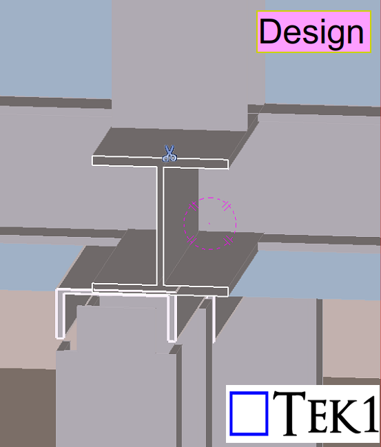
In this blog, we’ll share about a connection detail that we proposed to the engineer.
As per the design, a PFC beam needed to be supported by an I-beam above. However, in one location, the PFC beam was offset from the I-beam — and no connection detail was provided for this condition in the design drawings.
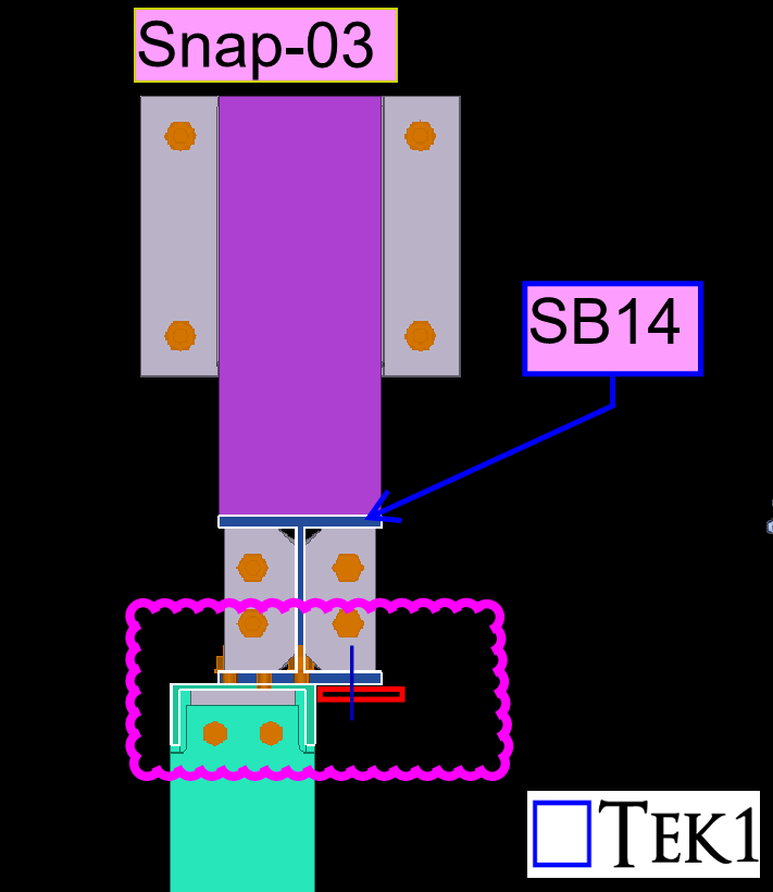
To address this, TEK1 proposed adding tab plates to connect the offset PFC beam securely. This solution maintained structural intent while resolving the missing detail.
The structural engineer reviewed our proposal and accepted it.See the below response from the engineer ‘Option shown in snap-03 accepted to maintain 2 bolts at each connection. Additional tab plate to be 80×10 FPBW to PFC. Bolt spacing to follow 140 gauge line of flange of SB14.‘
We go beyond drawings to ensure constructibility, reduce rework, and keep projects moving forward.Stay with TEK1 for more updates on steel detailing challenges and solutions in our upcoming blogs.
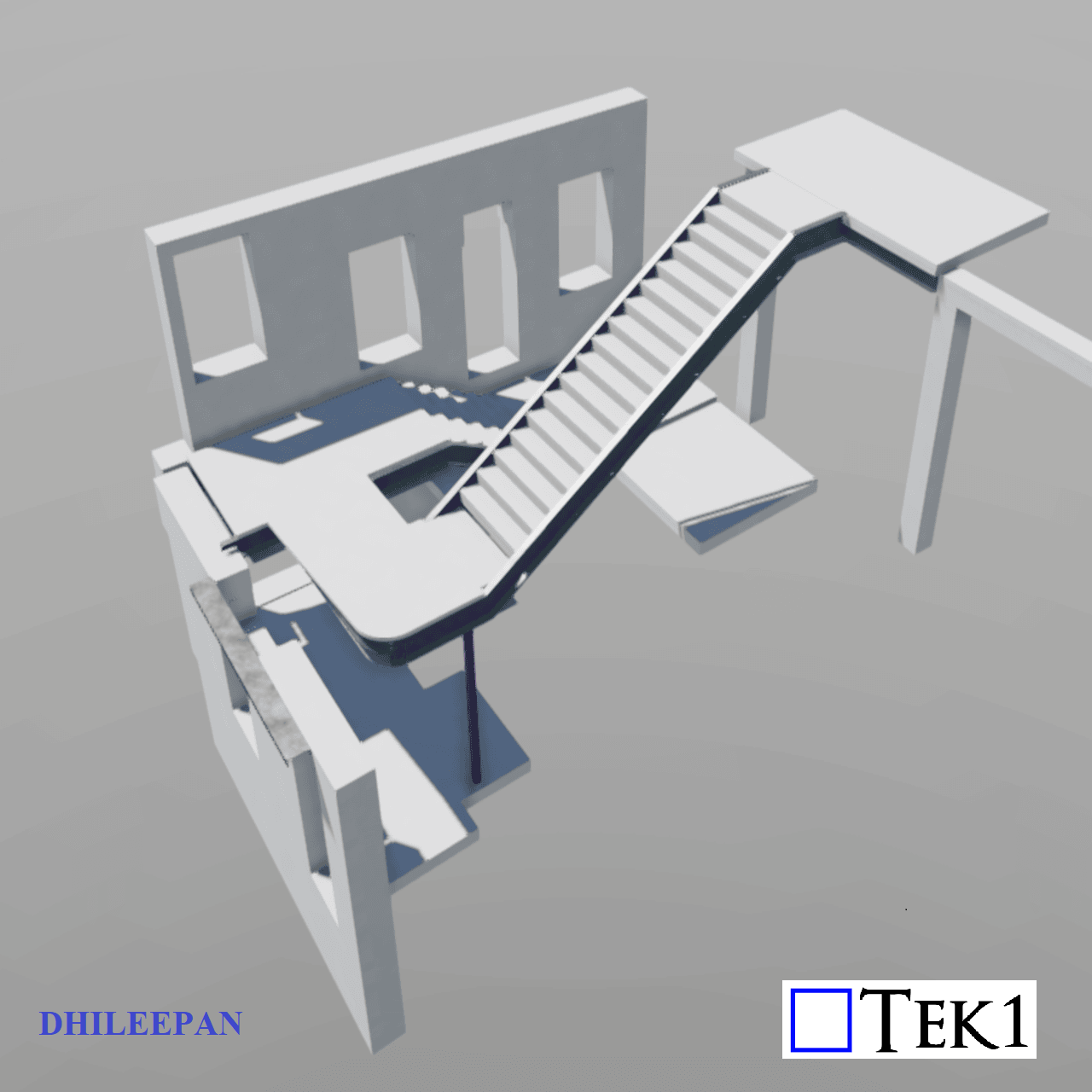
In our previous blogs, we discussed common mistakes that can occur while detailing a stair landing with slopes. You can find the link to the previous blog here: https://www.tek1.com.au/australian-standards/designing-a-multi-level-staircase-common-mistakes-and-key-considerations/
Now, the designers have replaced precast slabs with pavers. Since pavers cannot have varying thicknesses, we were instructed to do something with the steel structure to achieve the required falls. The stair landing system has steel frames, 10mm plates on their top & EA support members to bolt them. The 50mm pavers are placed on top of the 10mm plates.
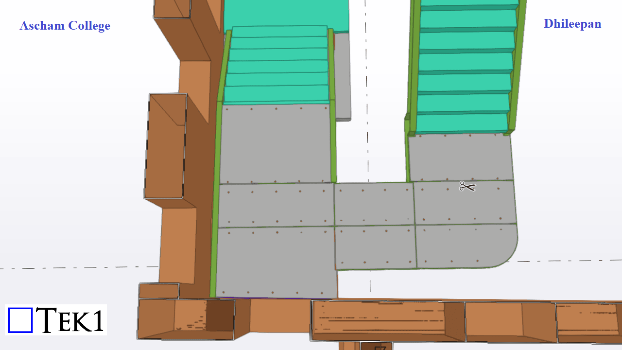
TEK1 played a key role in designing the modifications, adjusting the steel supports and slopes to achieve the necessary fall. If the required slope were unidirectional, achieving it would be straightforward. However, in this case, the stair turns 180°, and the mid-landing’s fall transitions in three directions.
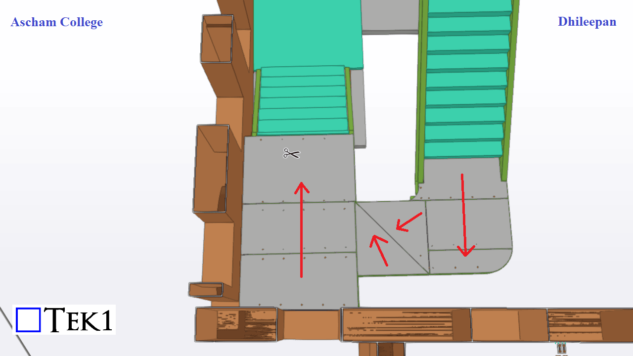
Handling Slope Transitions The landing below Flight-02 and the top of Flight-01 are in opposite 180° directions. A single rectangular plate cannot connect these two slopes seamlessly. To address this, we introduced two triangular plates in the middle to enable a smooth transition between the slope directions.
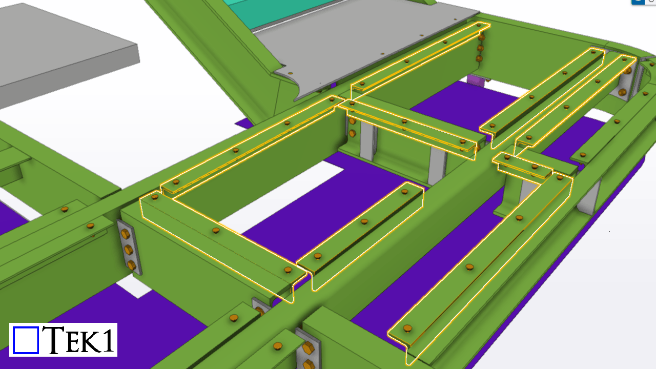
Structural Adjustments The main steel structural members remain consistent throughout the mid-landing. We adjusted the RL (Reduced Level) and slopes of the EA support members to match the required slope of the 10mm plates that support the pavers.
By implementing these changes, we successfully accommodated the required falls while ensuring structural integrity and proper drainage. This approach maintains a practical and efficient solution when using pavers instead of precast slabs in stair landings.