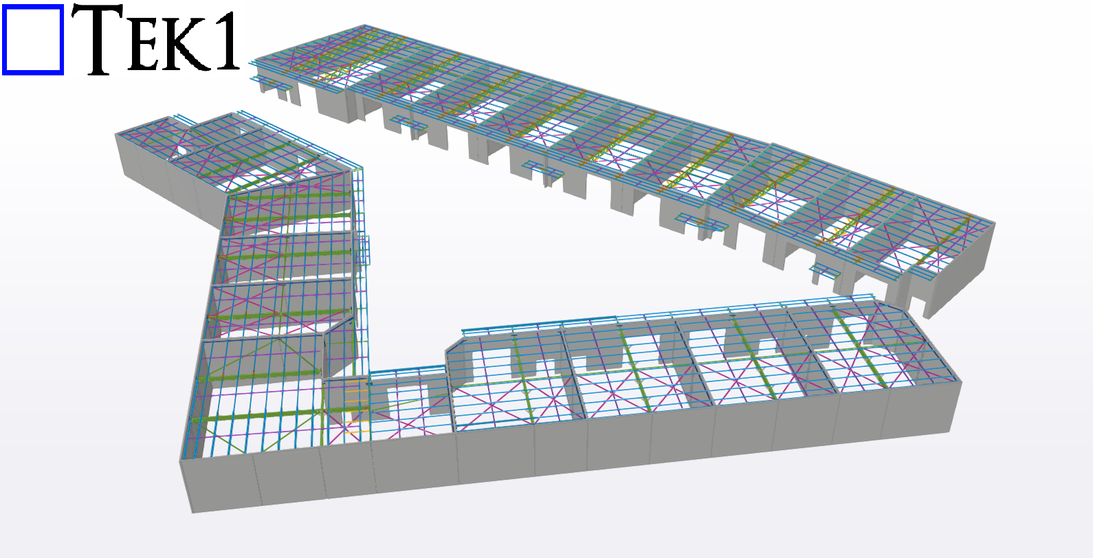
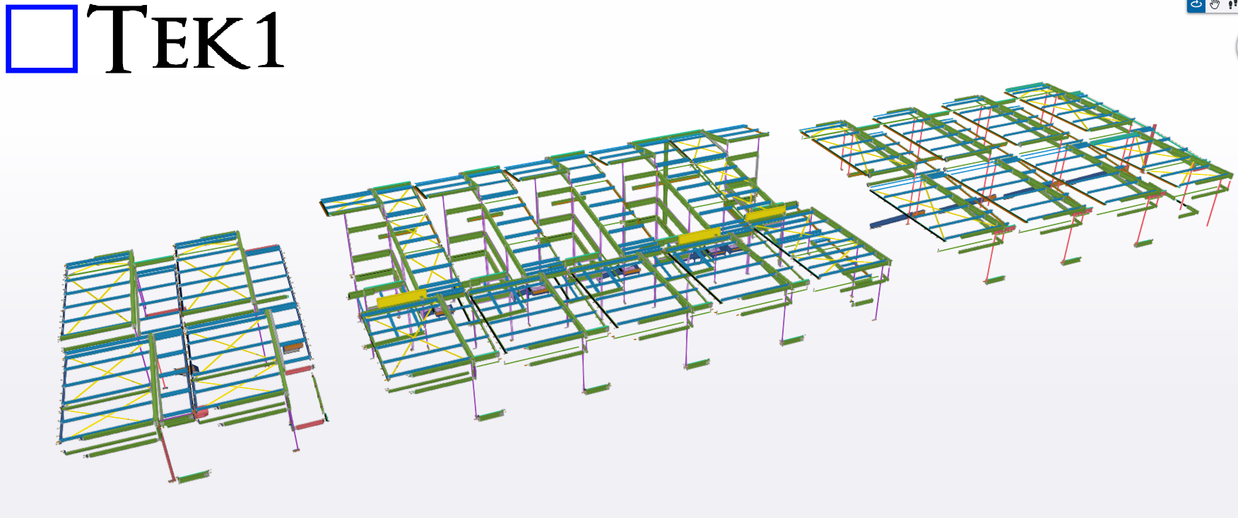
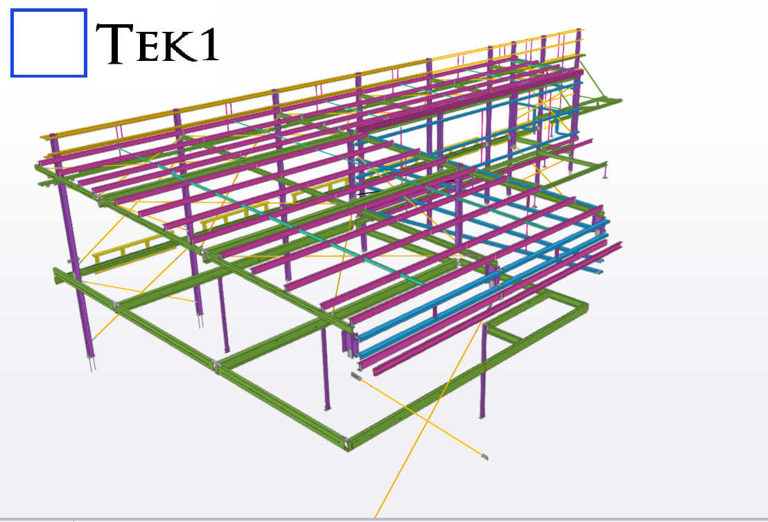
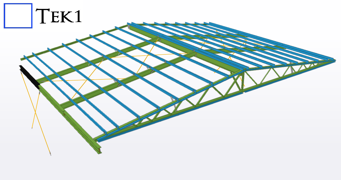
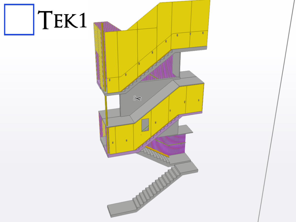
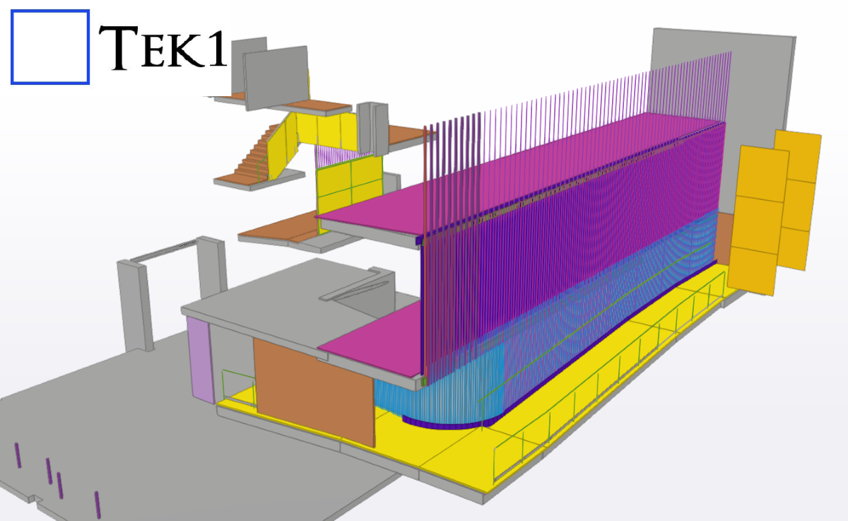
TEK1 completed a residential project for a prominent organization in Australia. Our primary scope was to provide the detailing drawings for the industrial units.
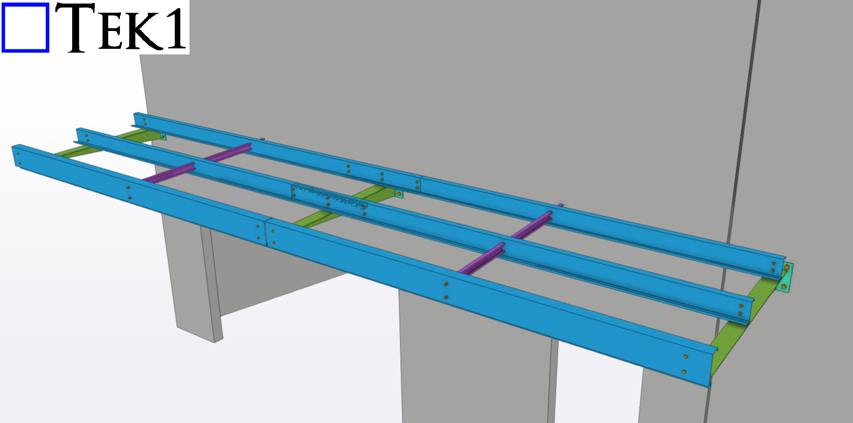
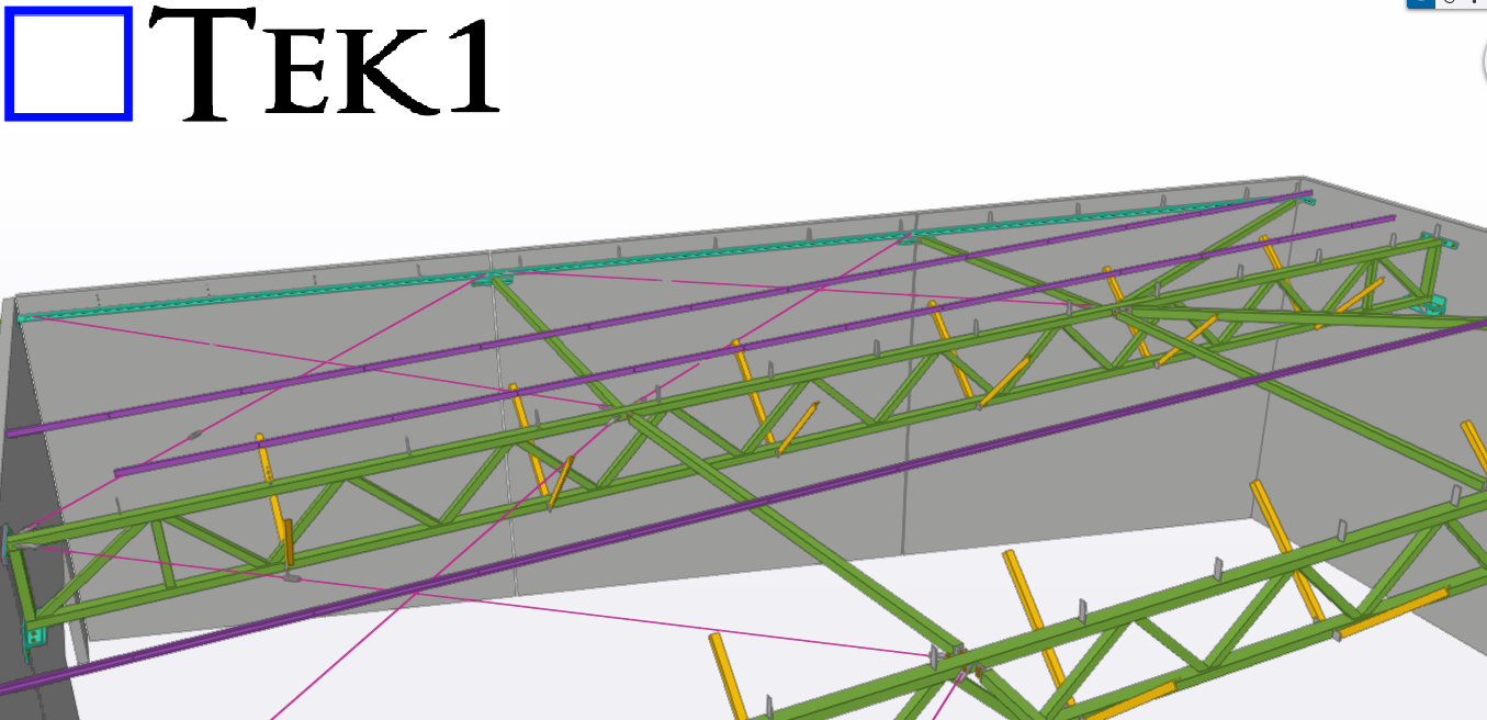
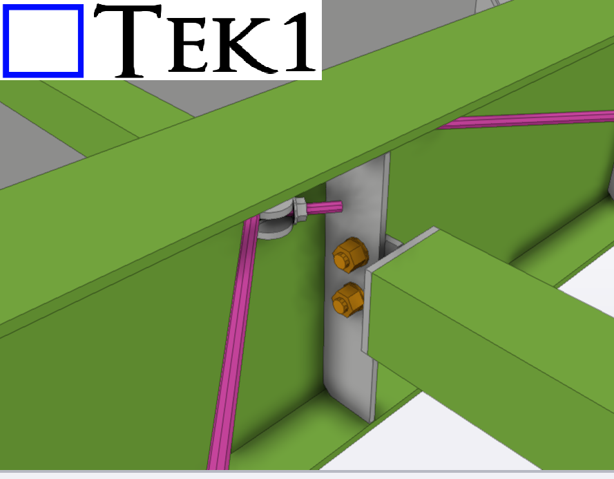
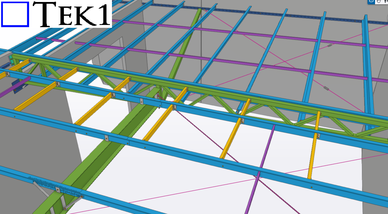
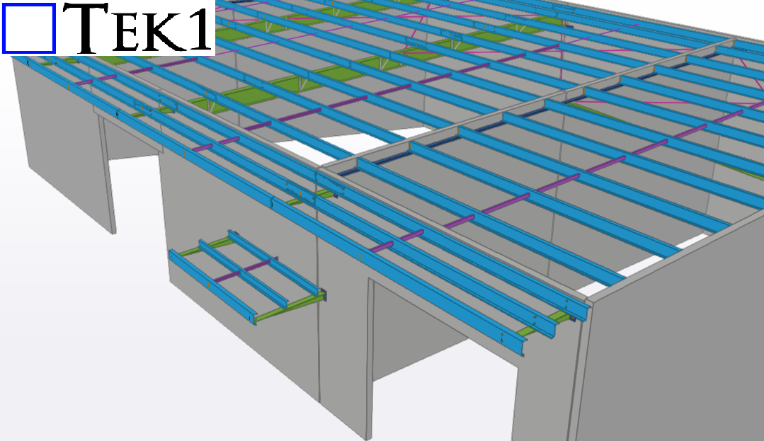
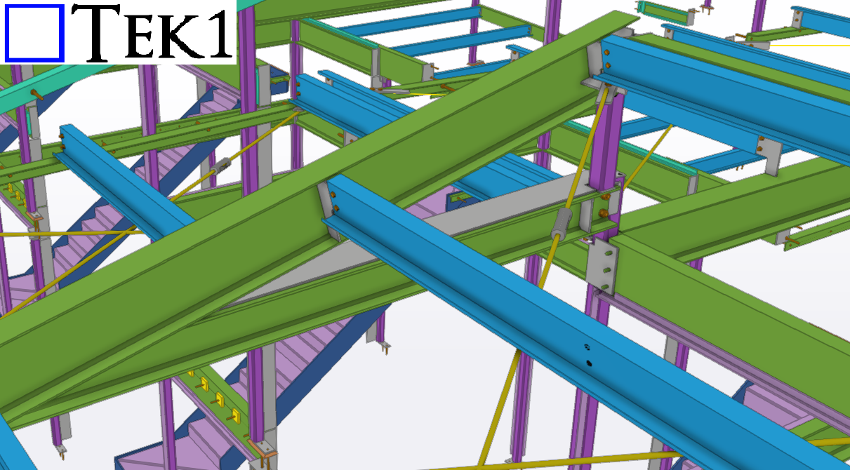
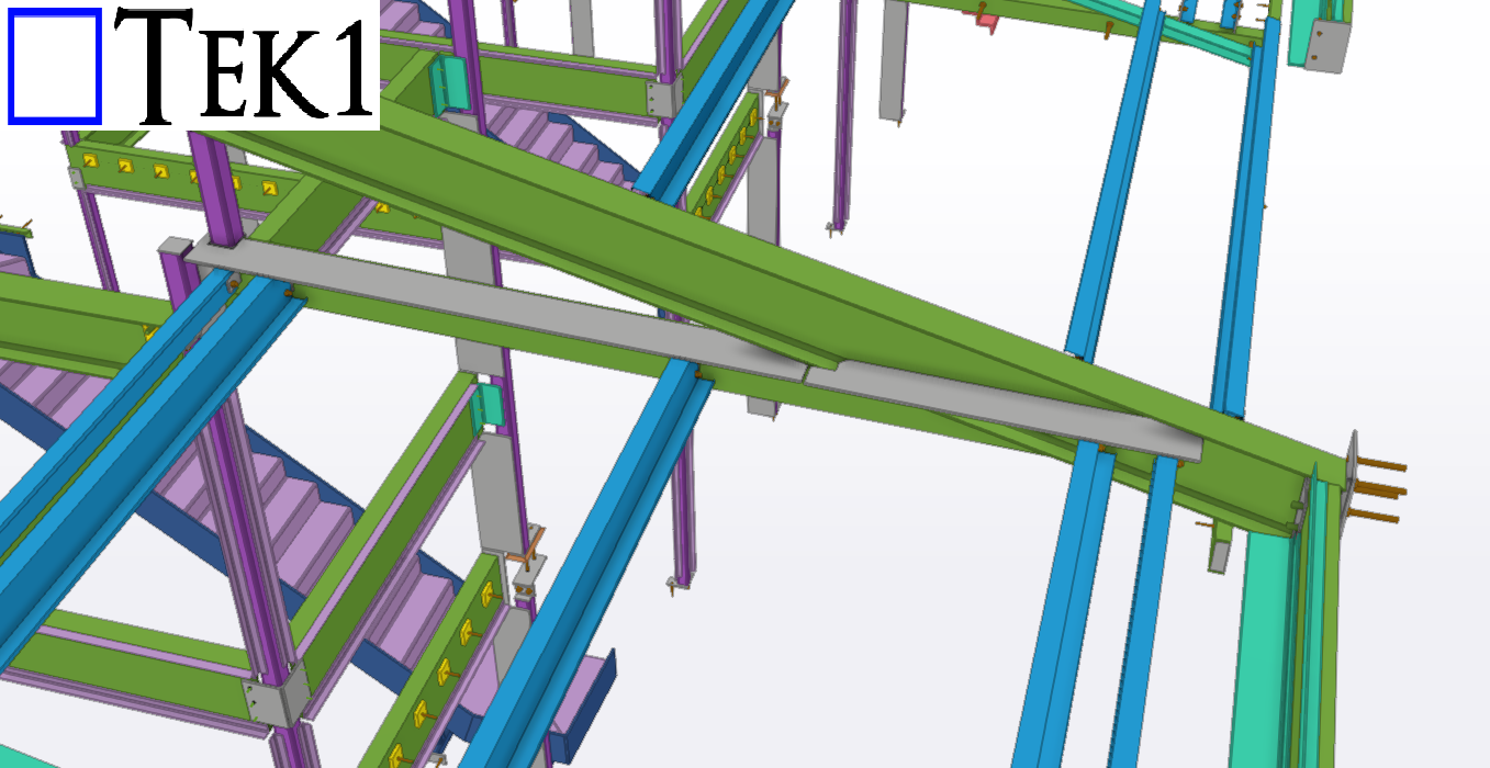
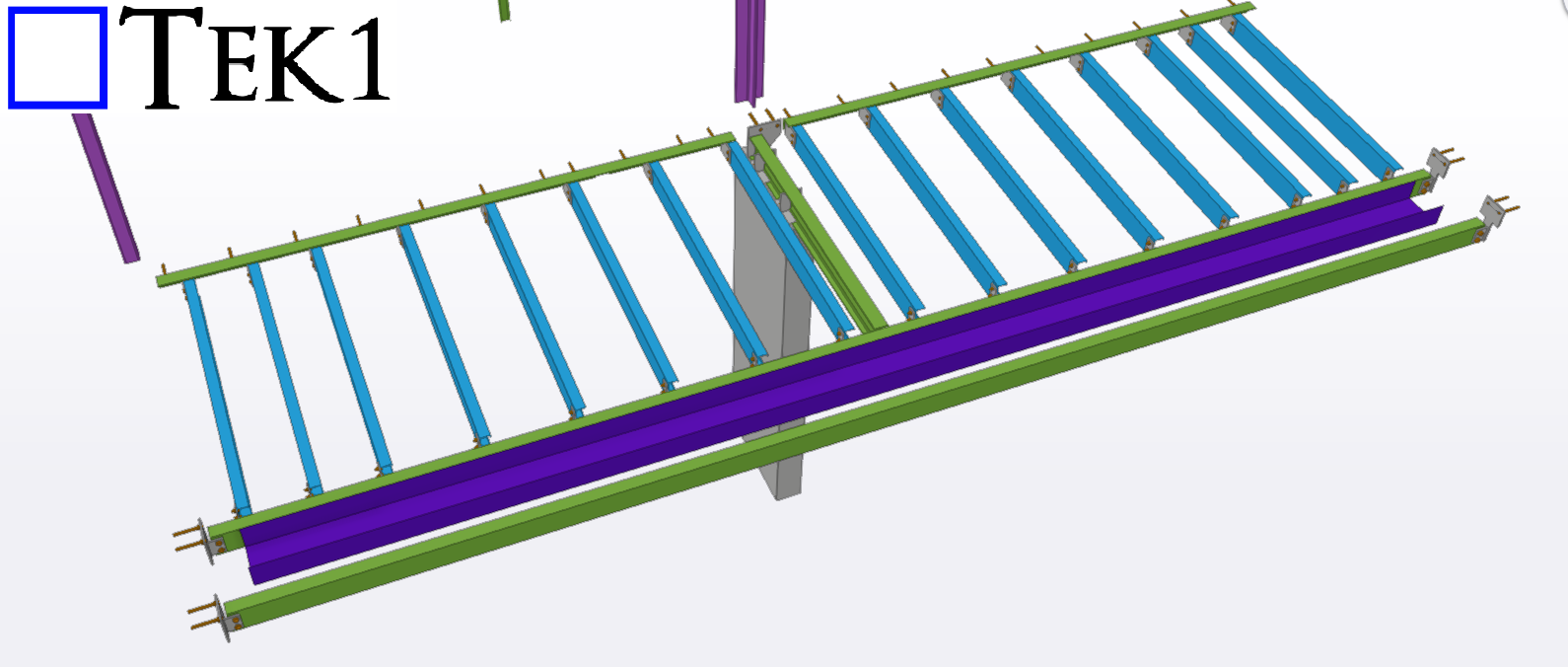
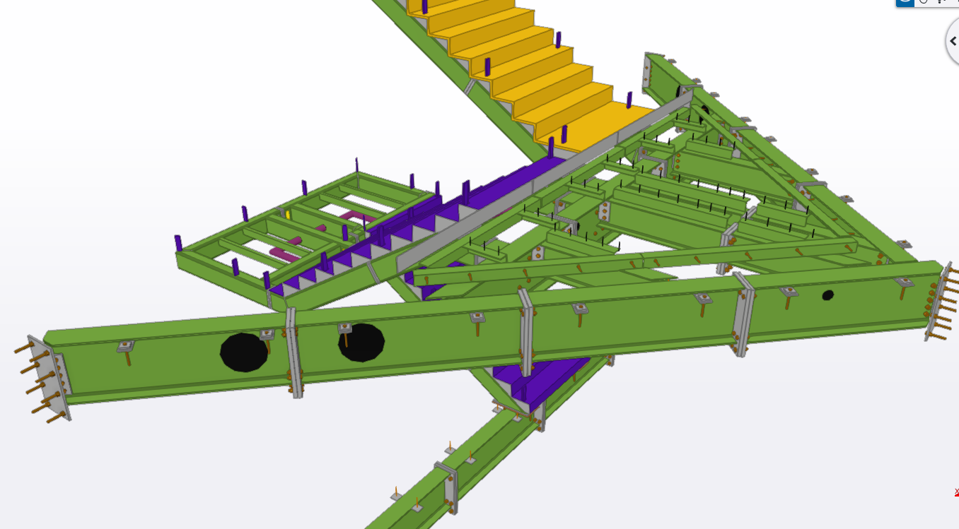
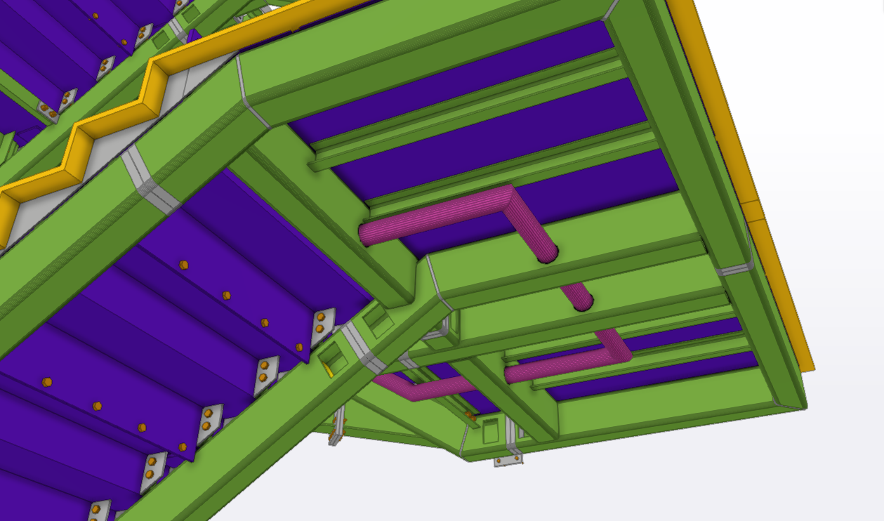
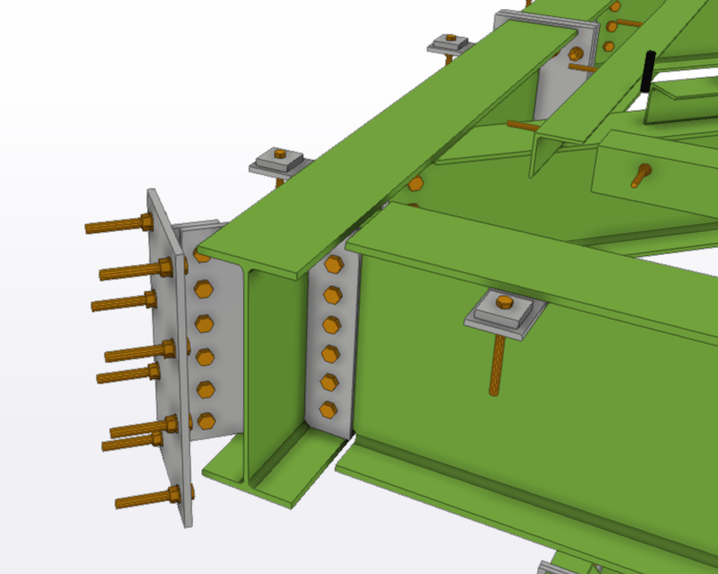
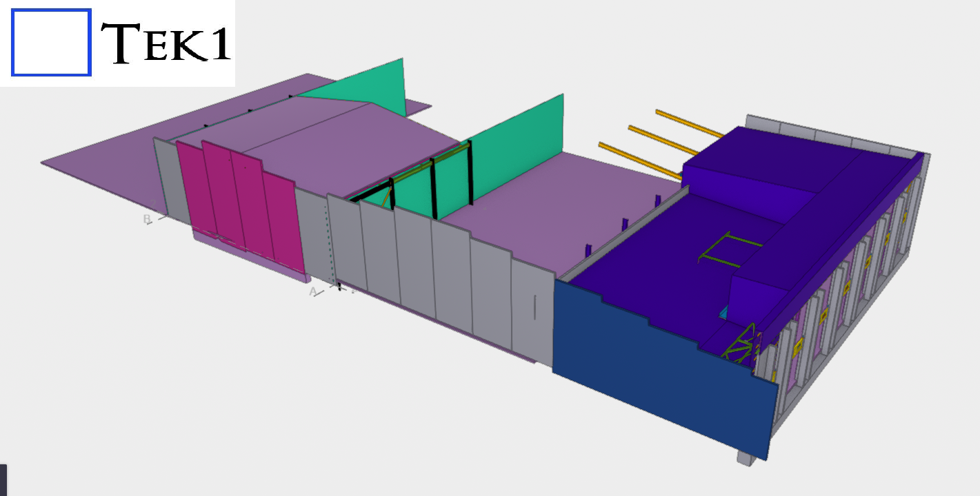
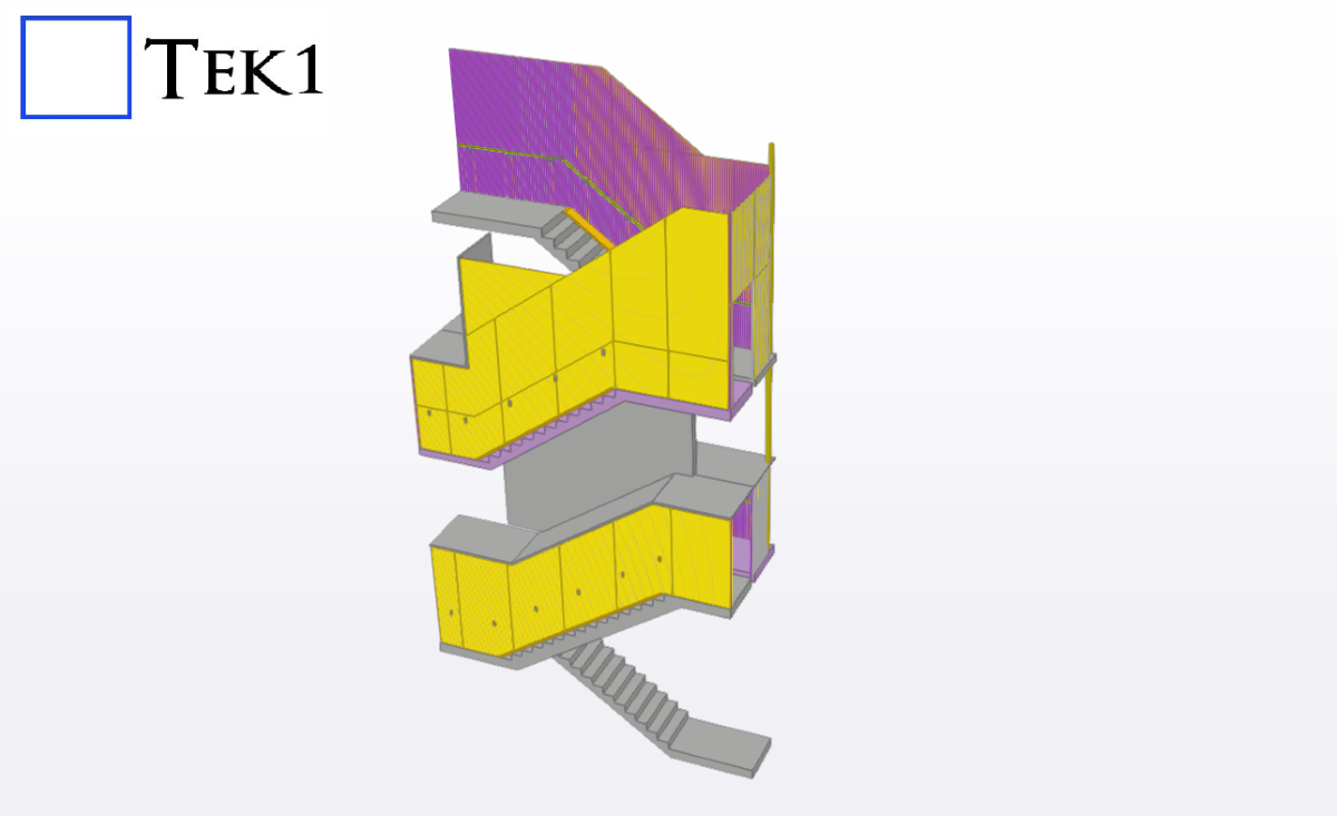
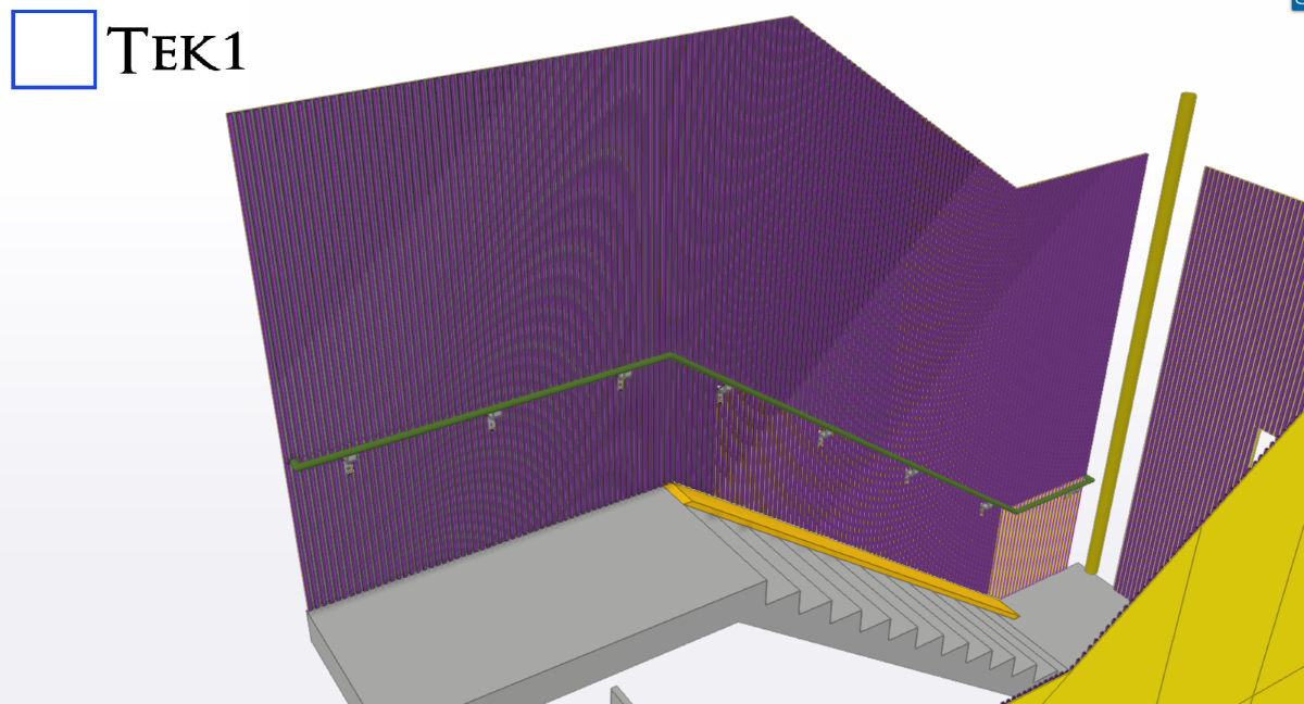
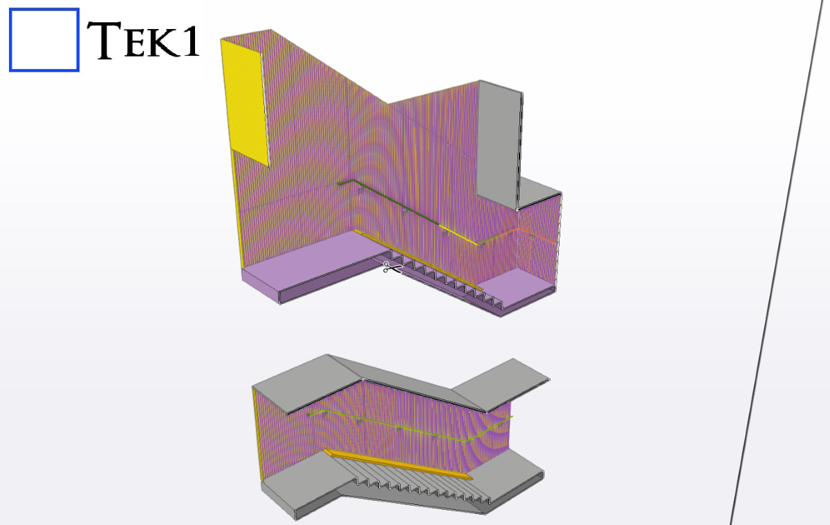
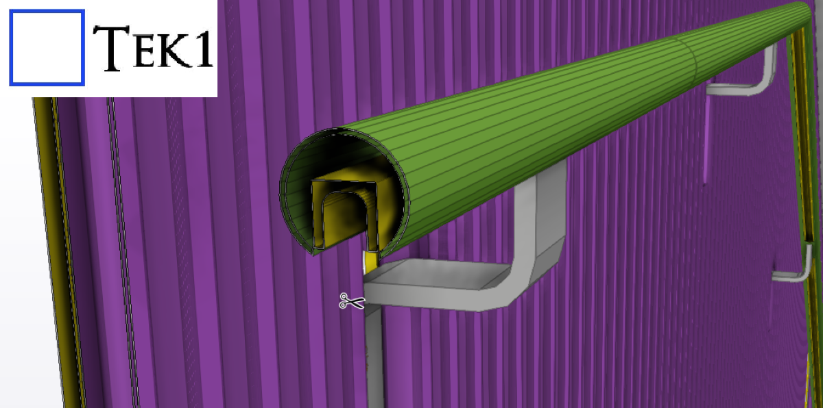
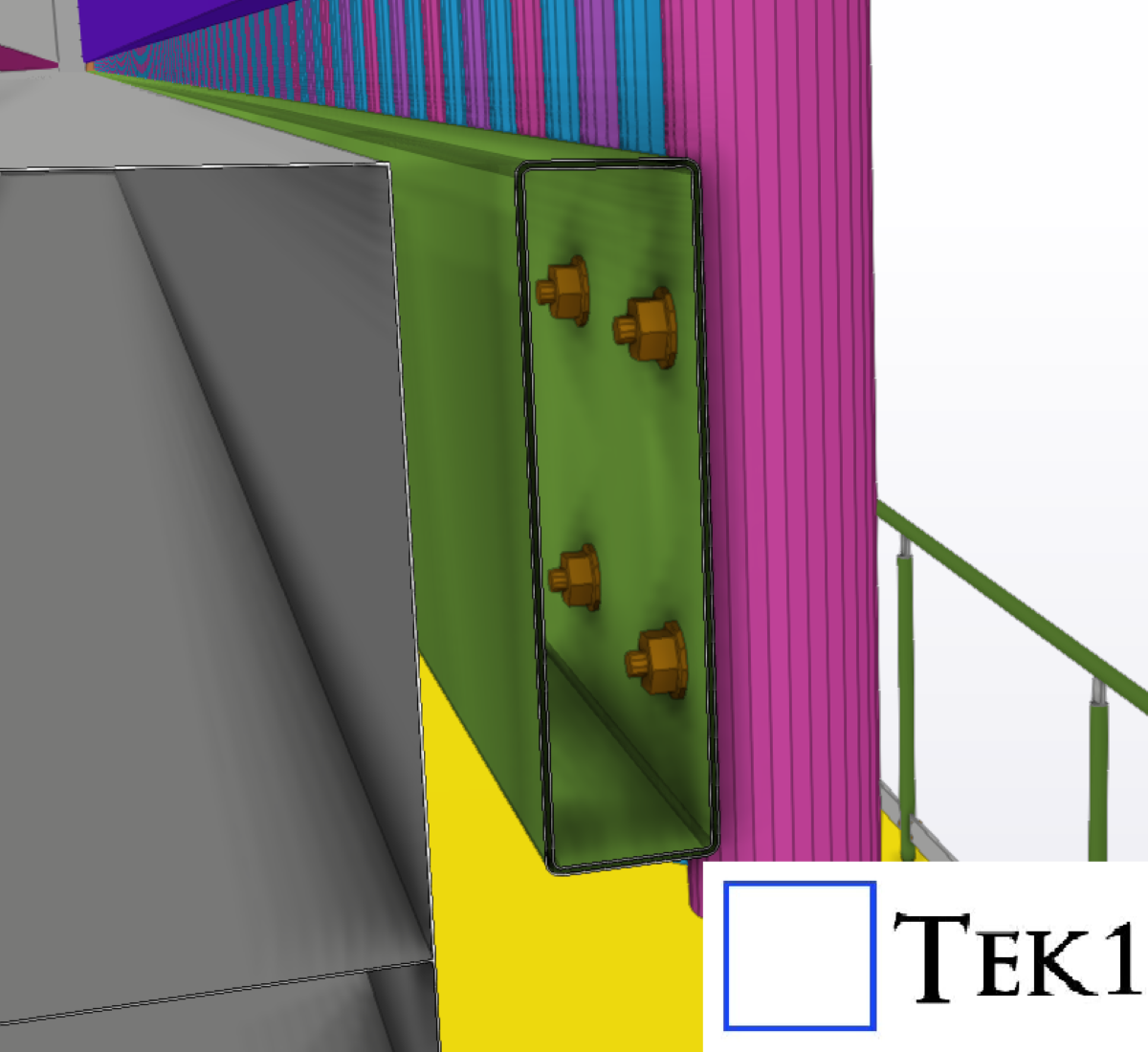
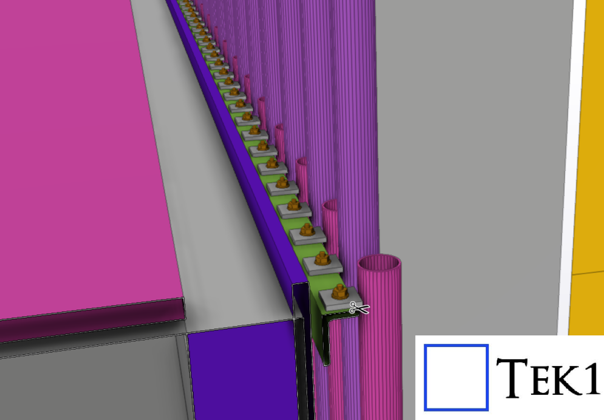
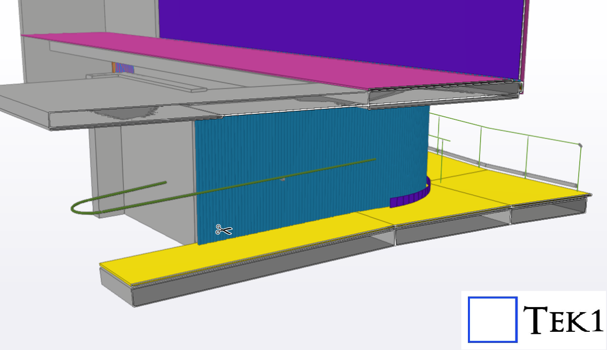
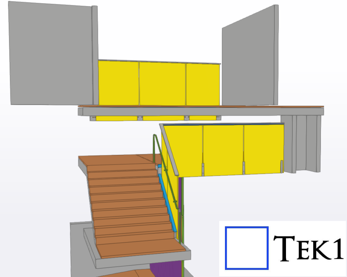
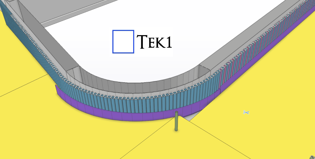
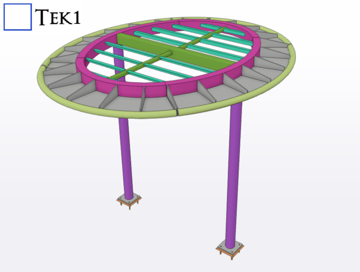
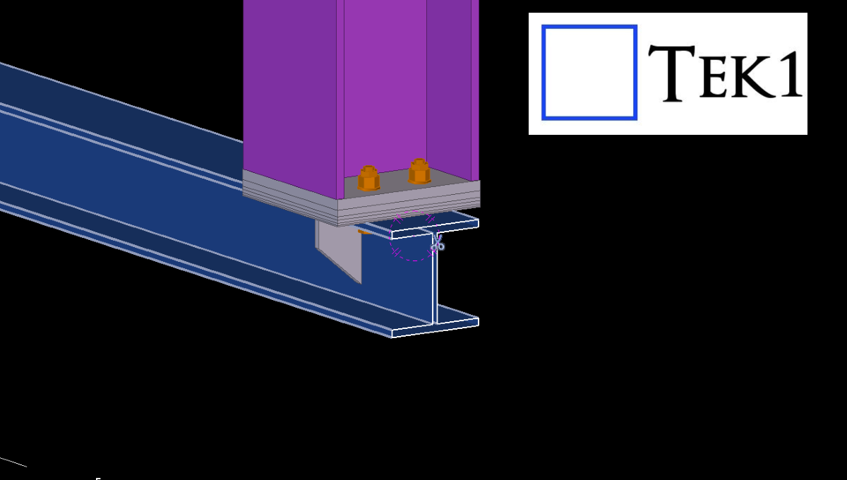
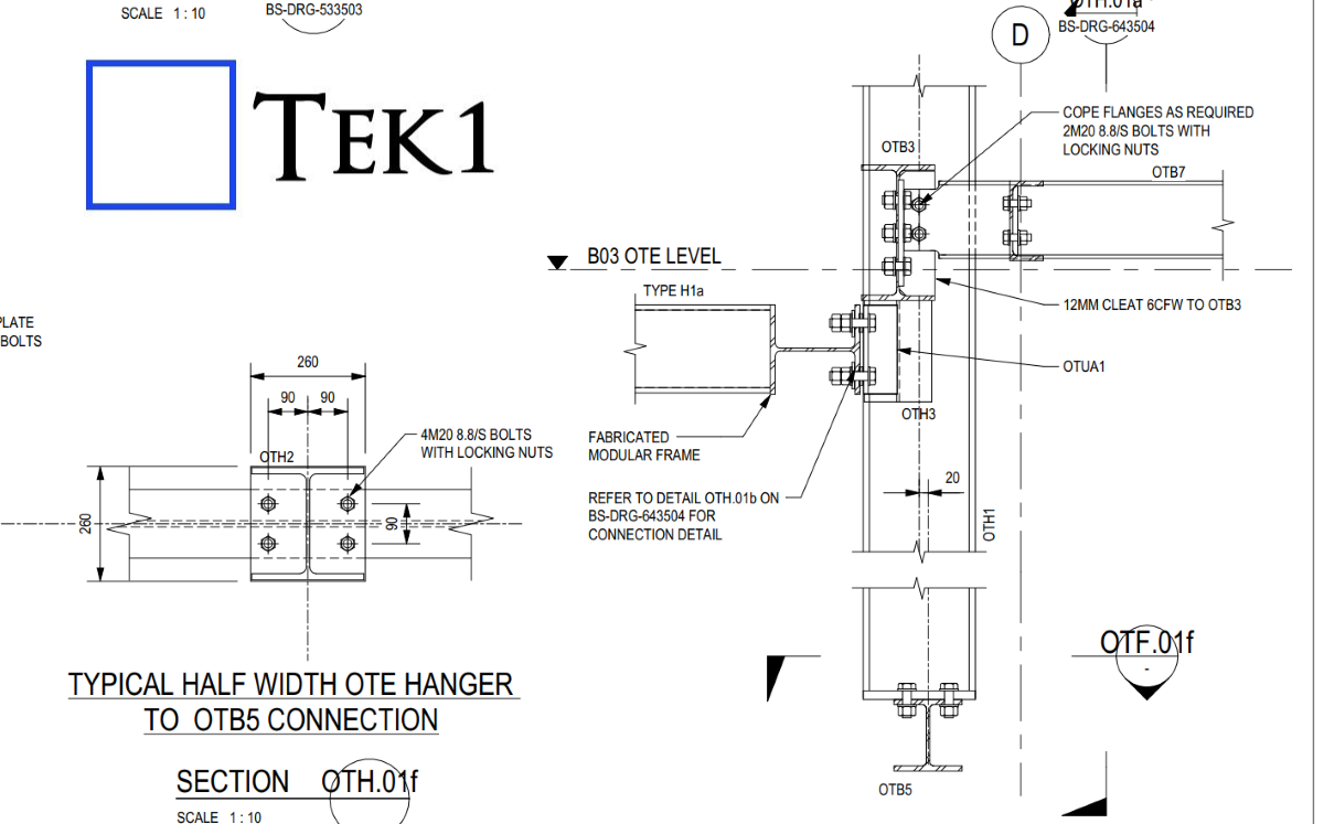
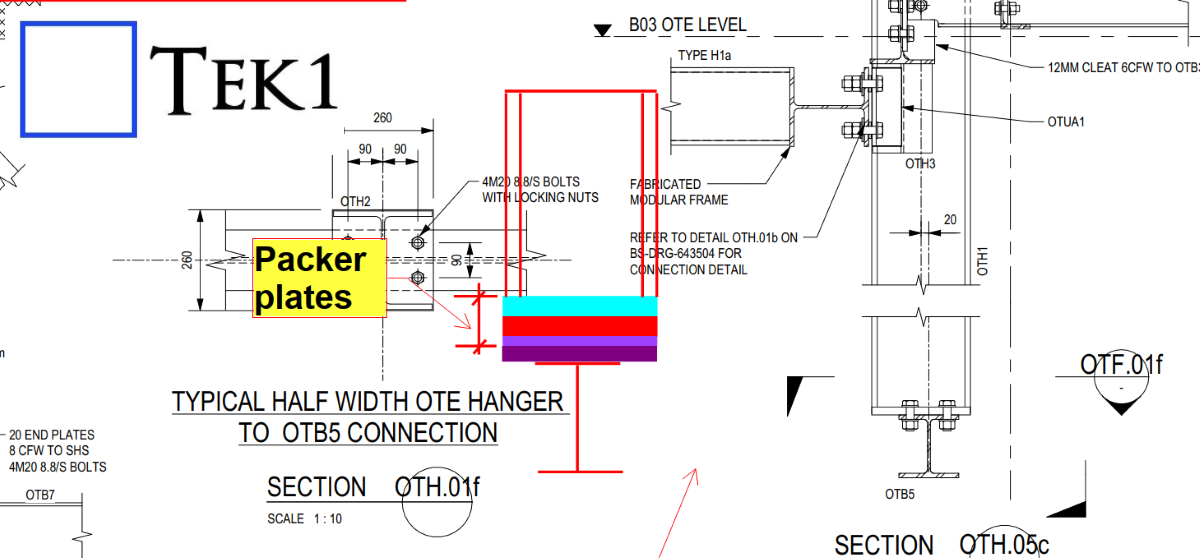
The project required close coordination with the precast detailer, as all the roof steel was supported by precast walls rather than conventional steel columns. This made accurate coordination critical to ensure all connections aligned correctly.
To achieve this, we conducted numerous coordination meetings with the client and the precast team, helping the project progress smoothly and minimizing the risk of site issues and rework.
.