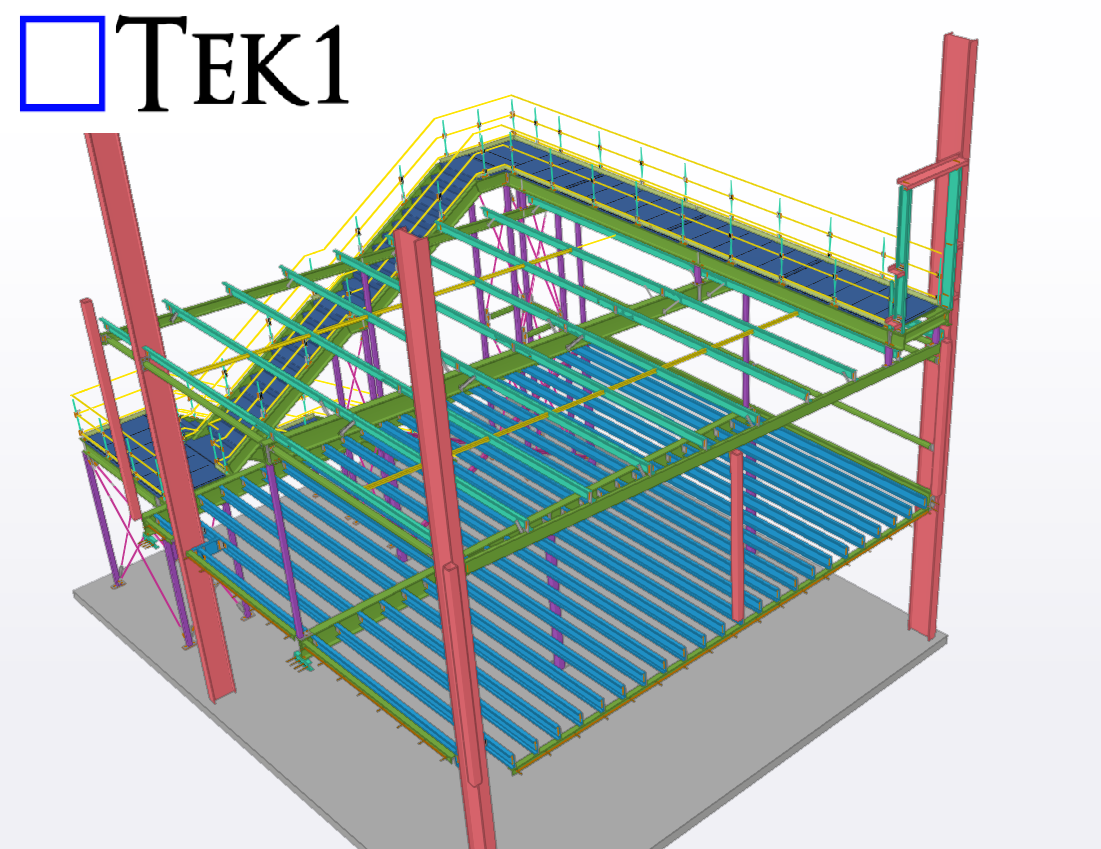
In Australian steel detailing, understanding roof and purlin specifications is essential for delivering precise and efficient designs. In this blog, I’ll share an experience highlighting the significance of addressing roof slope issues during detailing.
The Issue
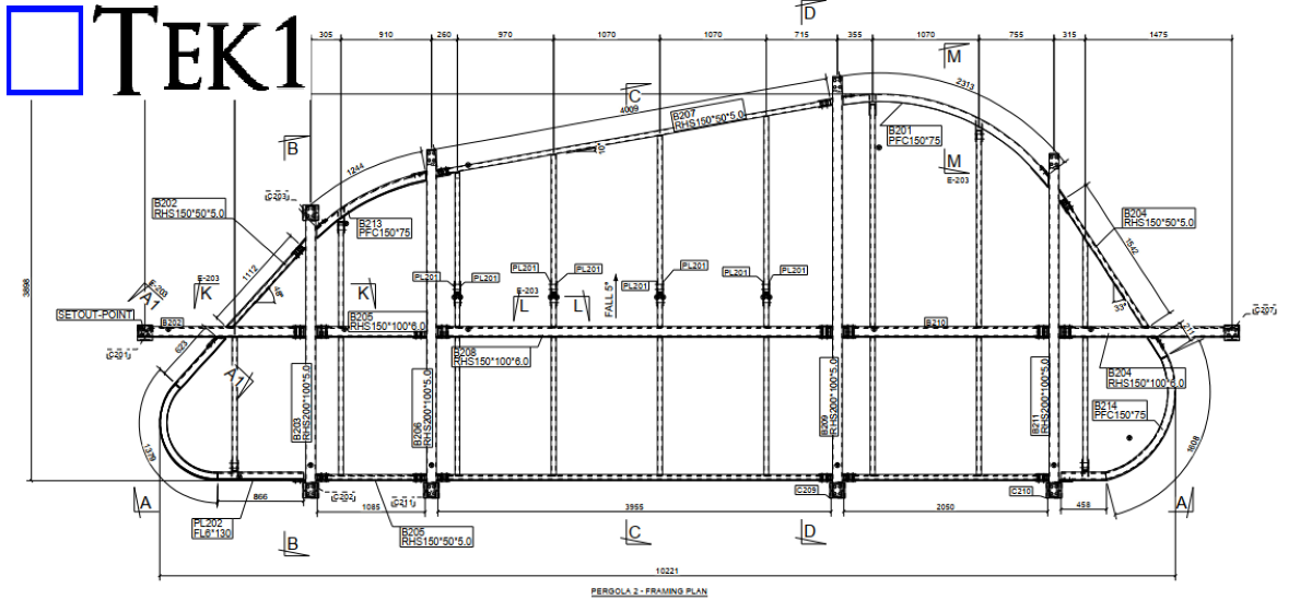
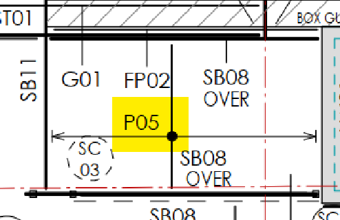
In a structural drawing, the purlins were shown running north-south, which suggested that the roof slope would be east-west (since purlins are always perpendicular to the roof slope). However, when we reviewed the architectural drawings, the roof slope was indicated as running north-south—a direct contradiction.
The Resolution
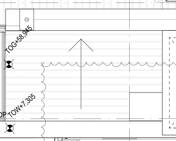
We raised the issue with the client, who confirmed that the architectural drawings superseded the structural ones. Following this clarification, updated drawings were issued, with the roof slope correctly aligned in the east-west direction.
Key Takeaways
- Cross-Check Drawings: Always verify alignment between structural and architectural drawings, especially for critical elements like roof slopes.
- Communicate Early: Raising discrepancies early saves time and prevents costly rework.
- Stay Updated: Ensure you work with the most recent drawings to avoid confusion.
Roof and purlin alignment might seem straightforward, but even small errors can have significant implications. Attention to detail and proactive communication are key to successful detailing.