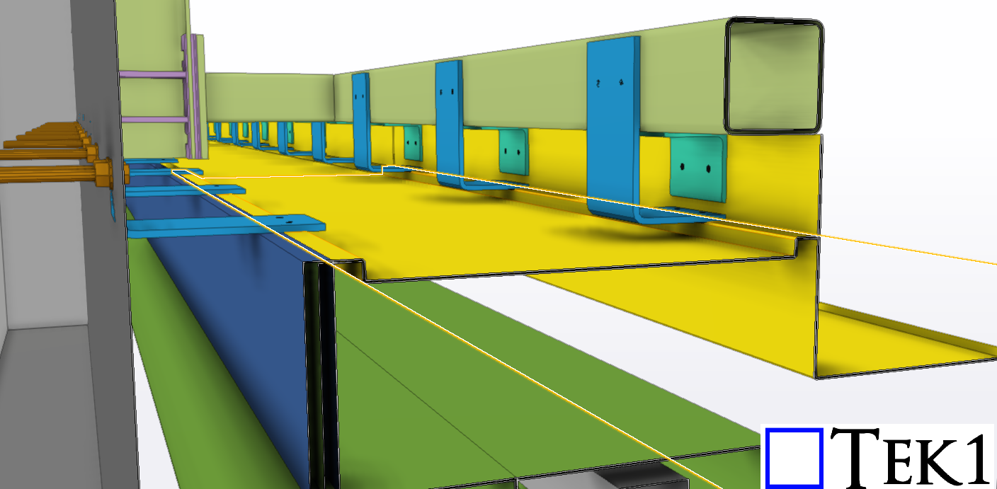
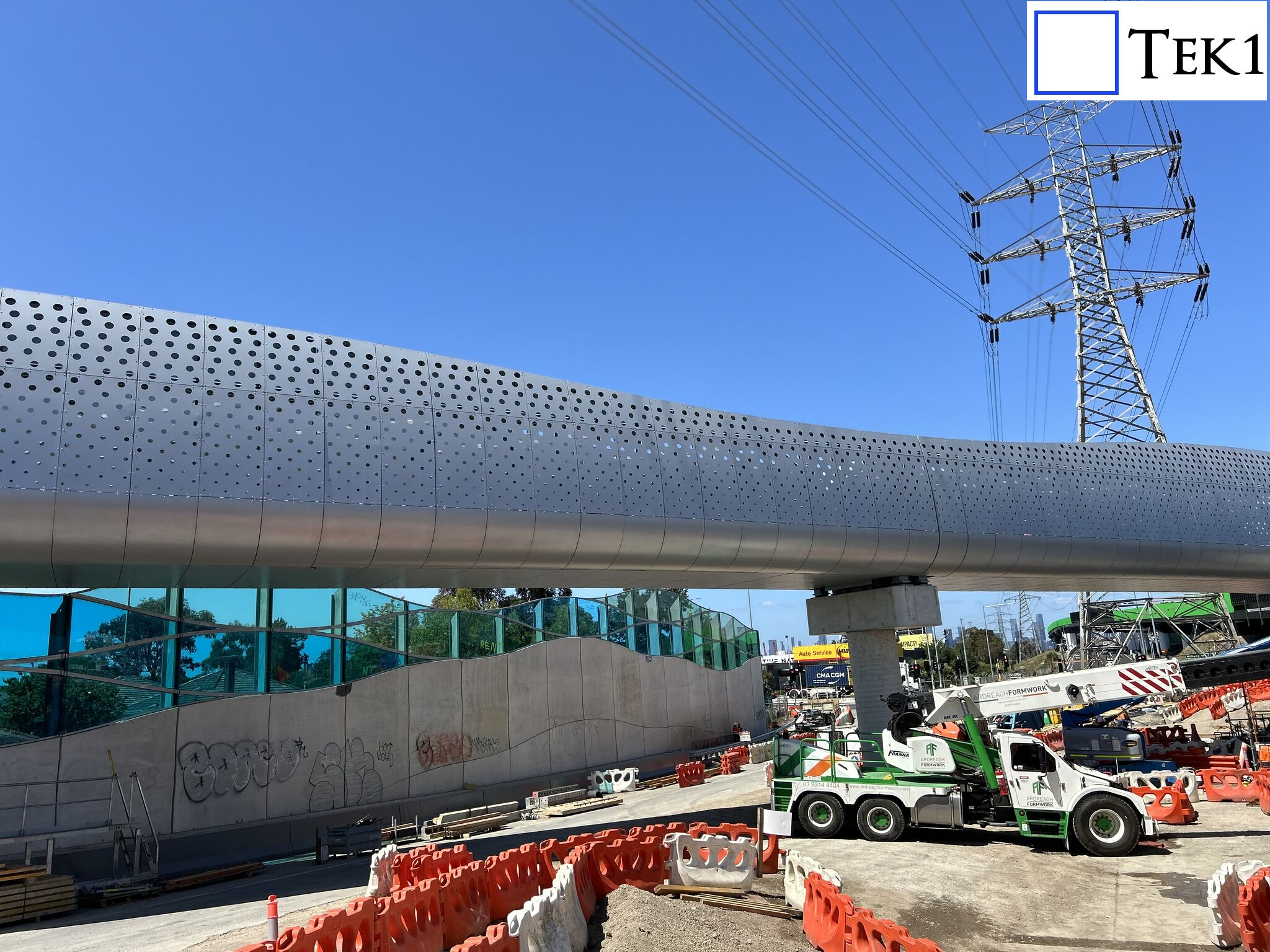
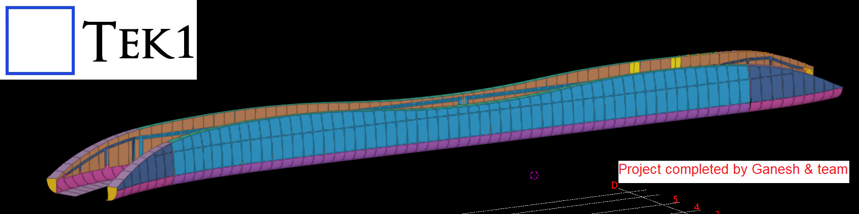
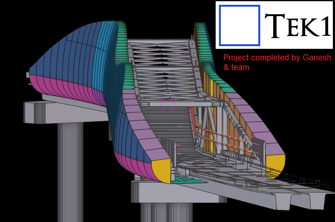
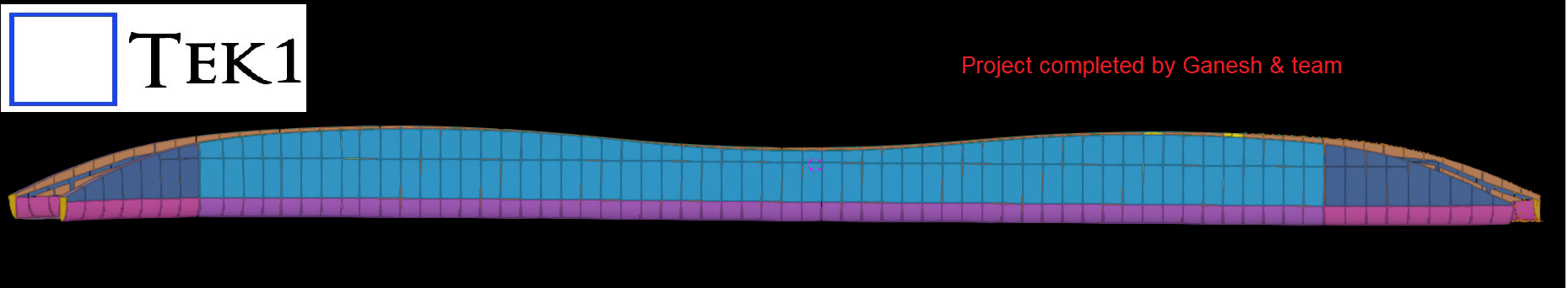
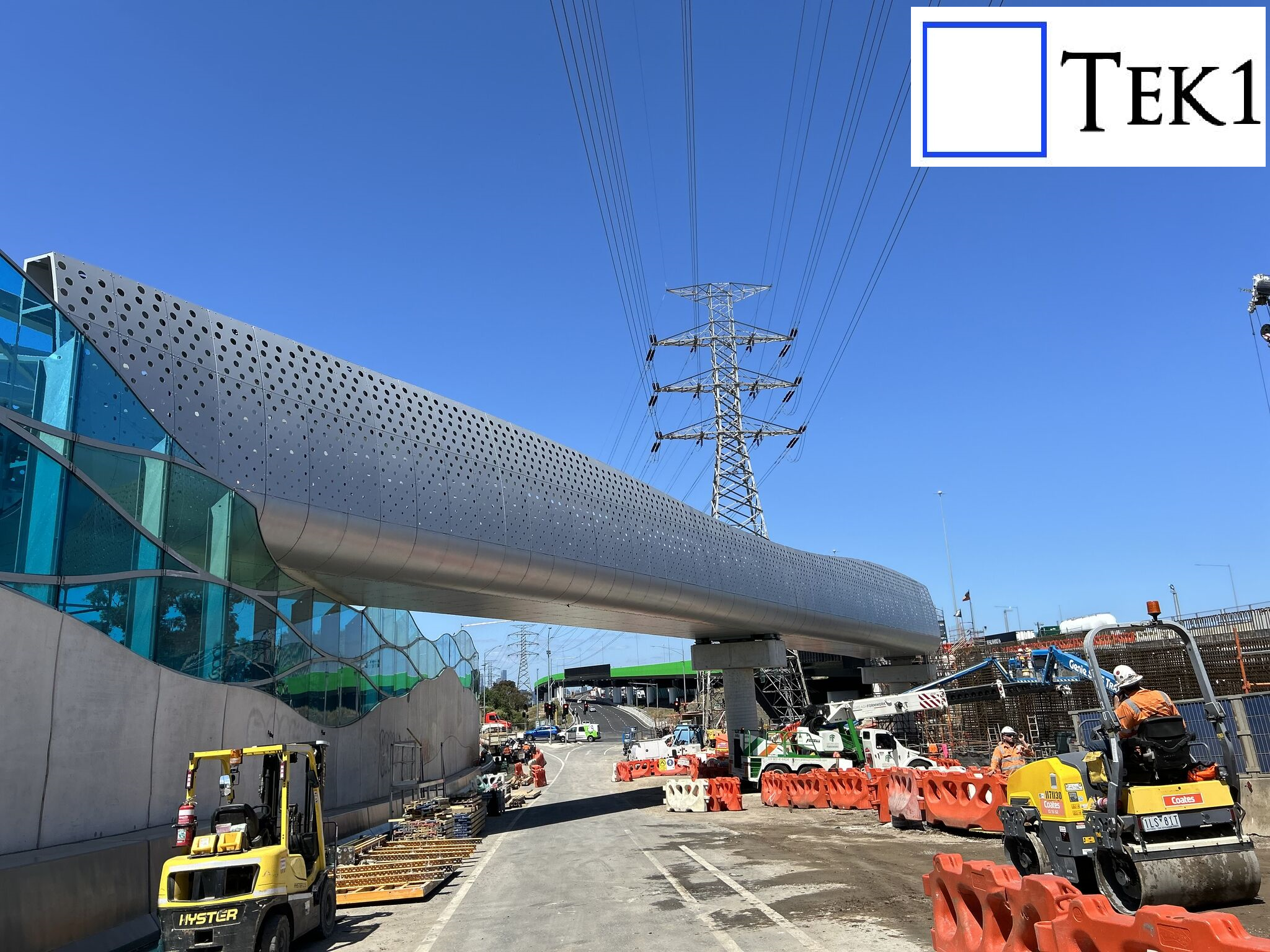
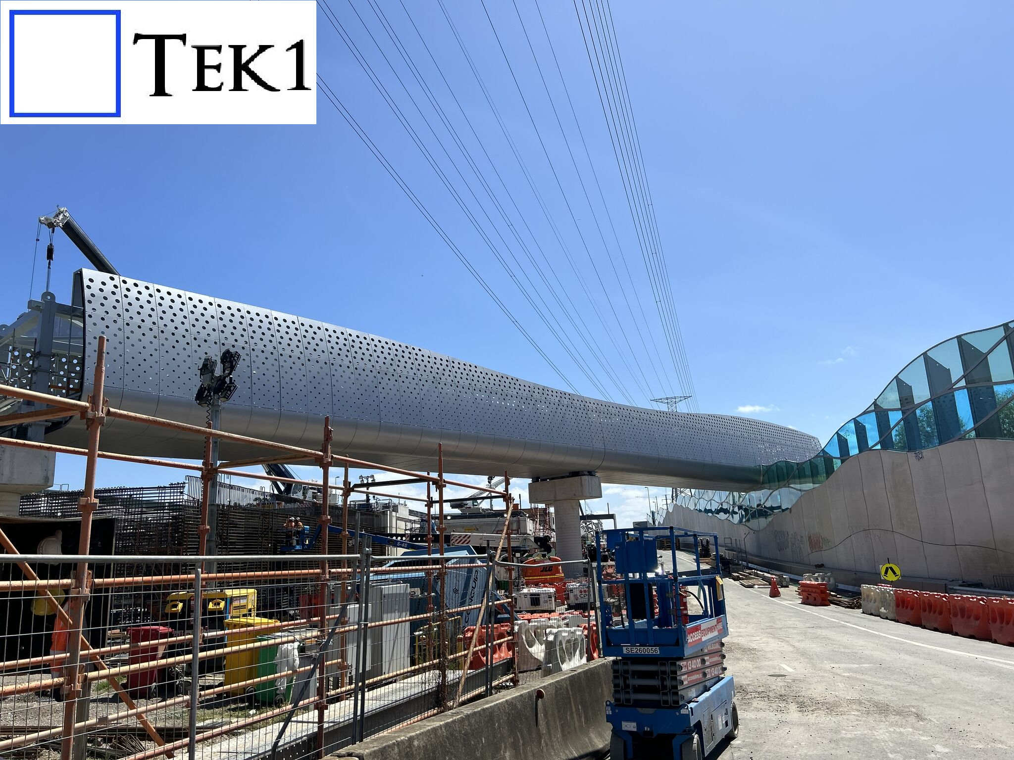
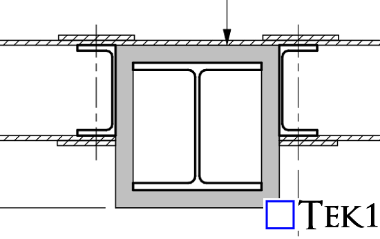
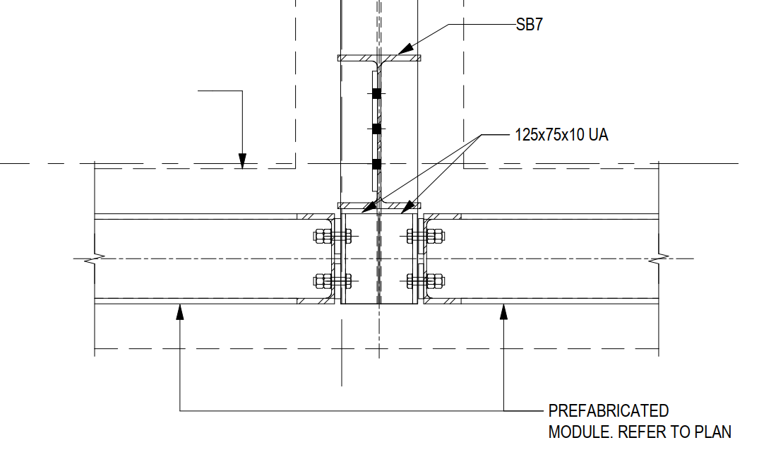
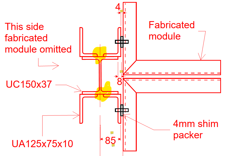
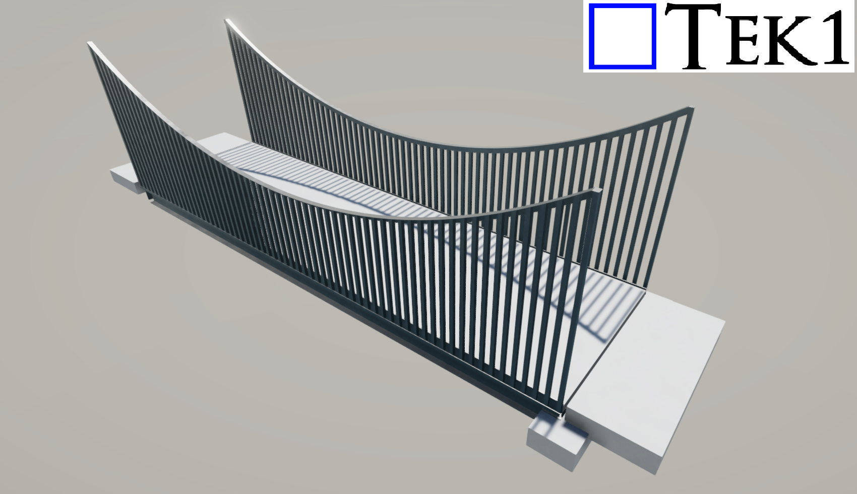
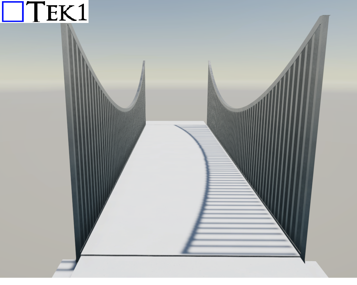
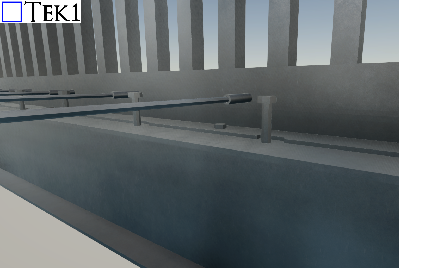
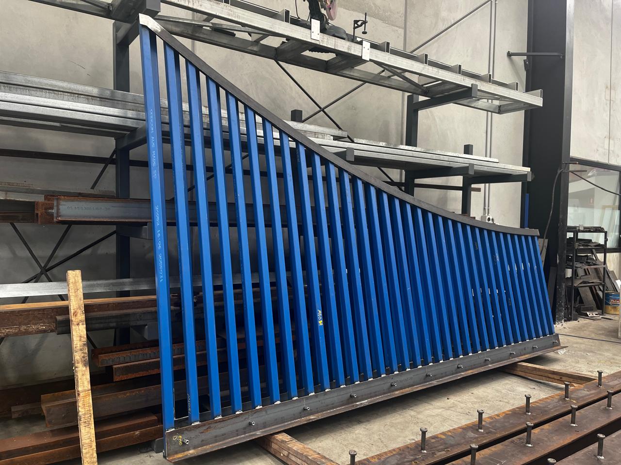
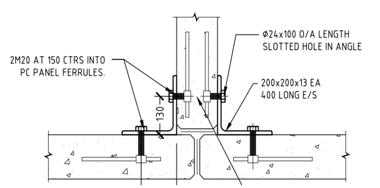
TEK1 recently completed a media wall support project for a prominent organization in Australia. The goal was to provide detailed support steelwork for a large media wall screen — with a unique challenge.
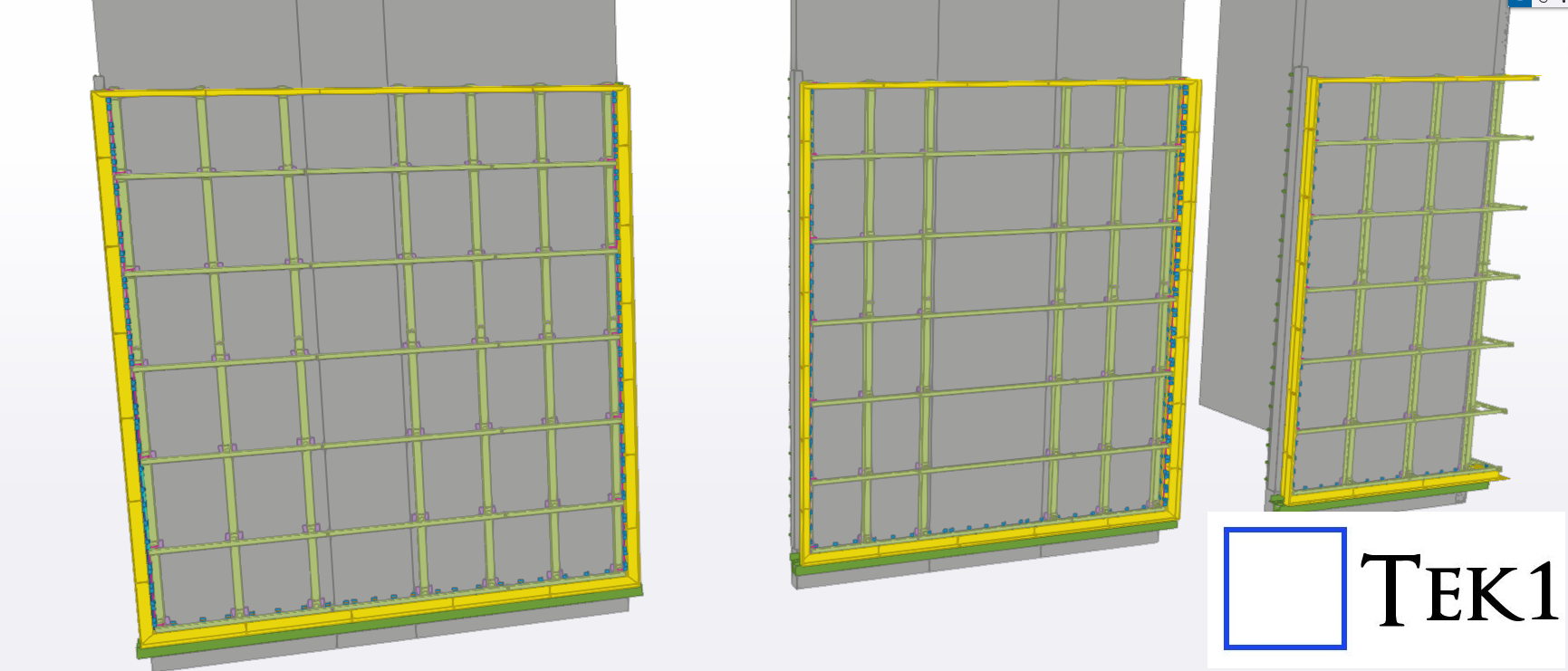
Unlike most projects, we didn’t receive any structural design drawings. Instead, we were given only a concept design, leaving it to TEK1 to determine suitable steel profiles and connection details.
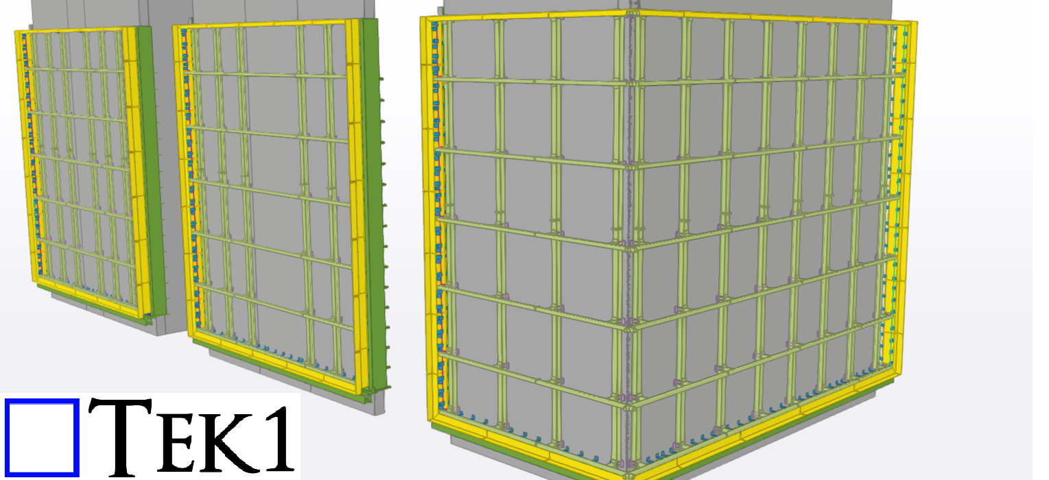
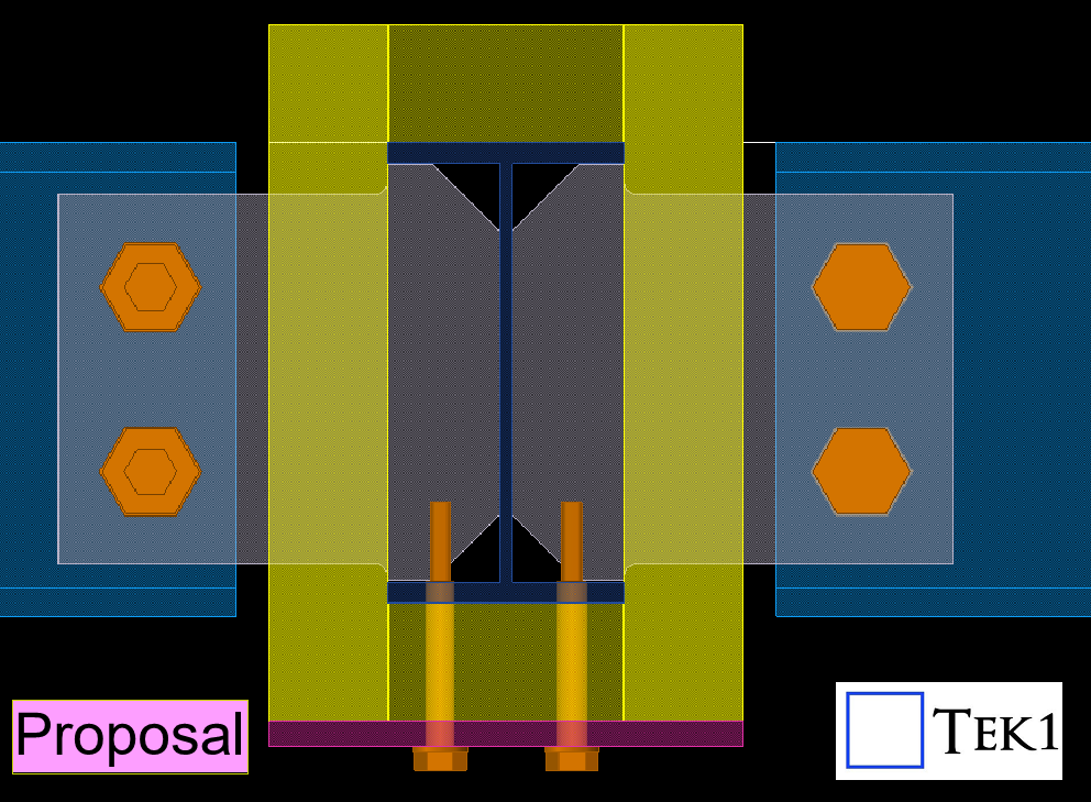
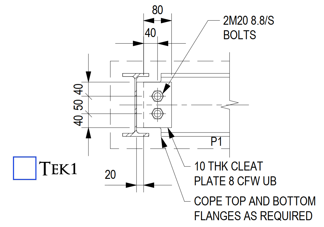
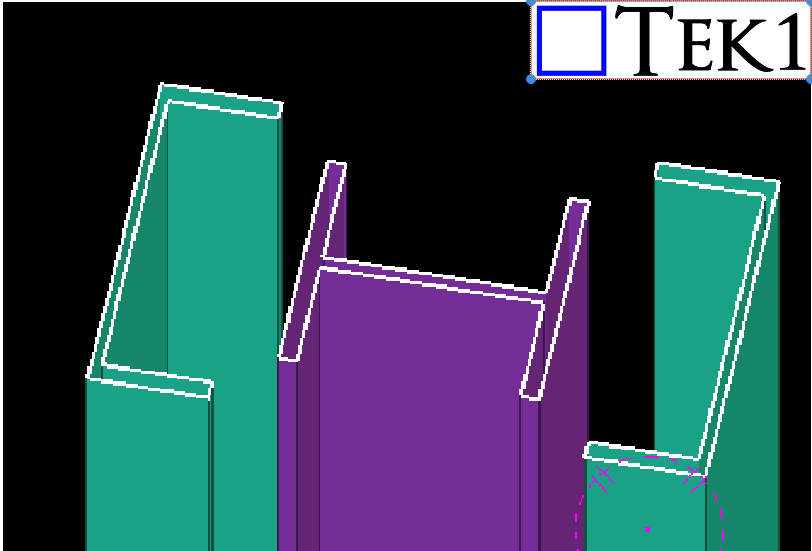
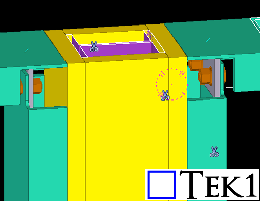
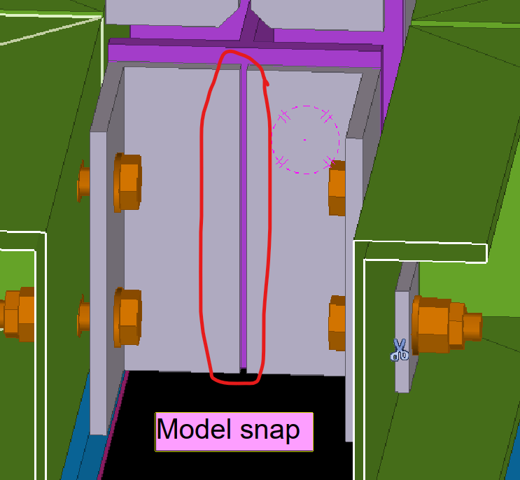
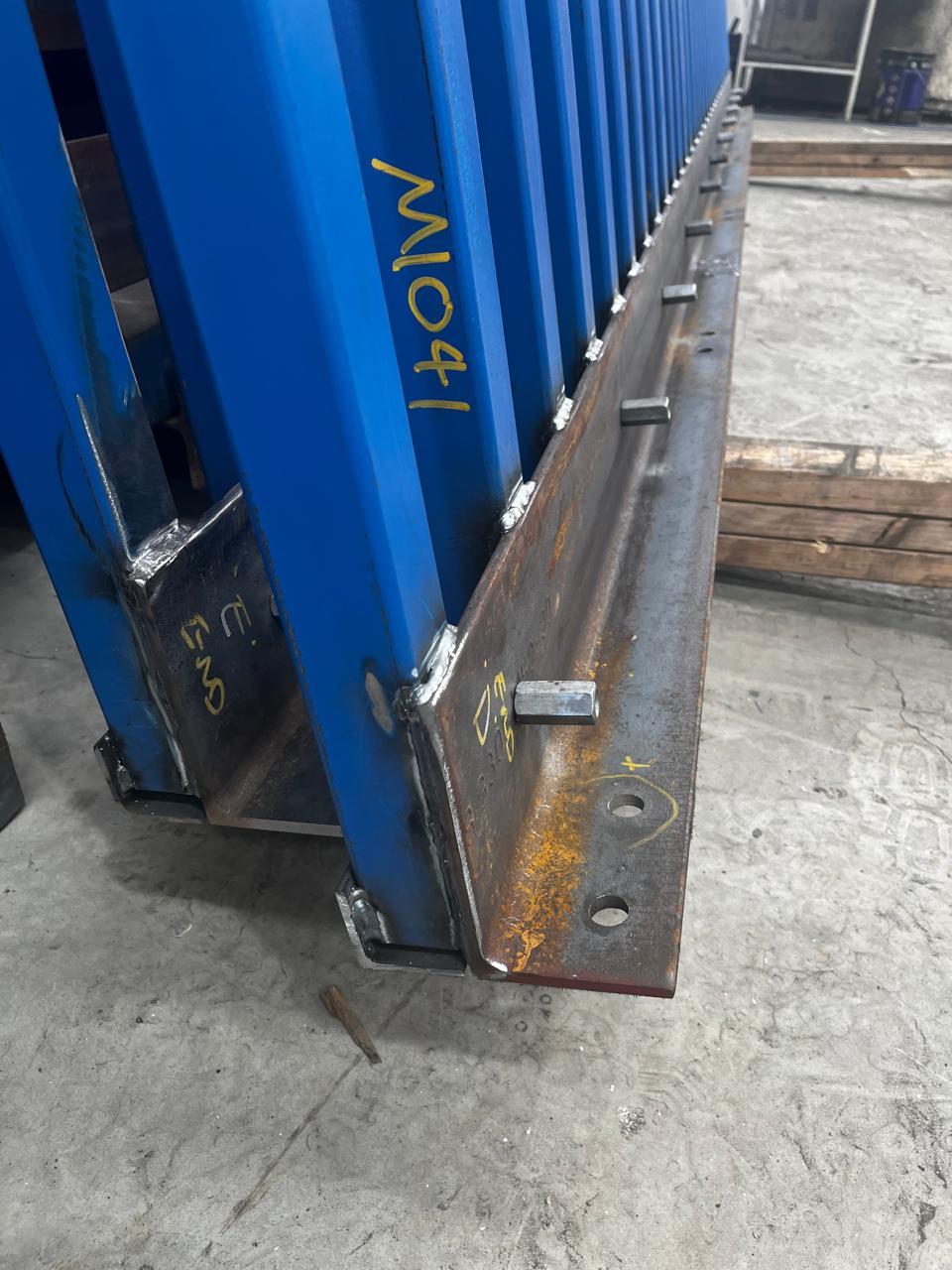
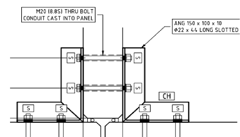
Our team carefully studied the concept and nominated appropriate profiles for each connection based on feasibility, strength, and ease of fabrication. Once the detailing was complete, we submitted it to the structural engineer for review.
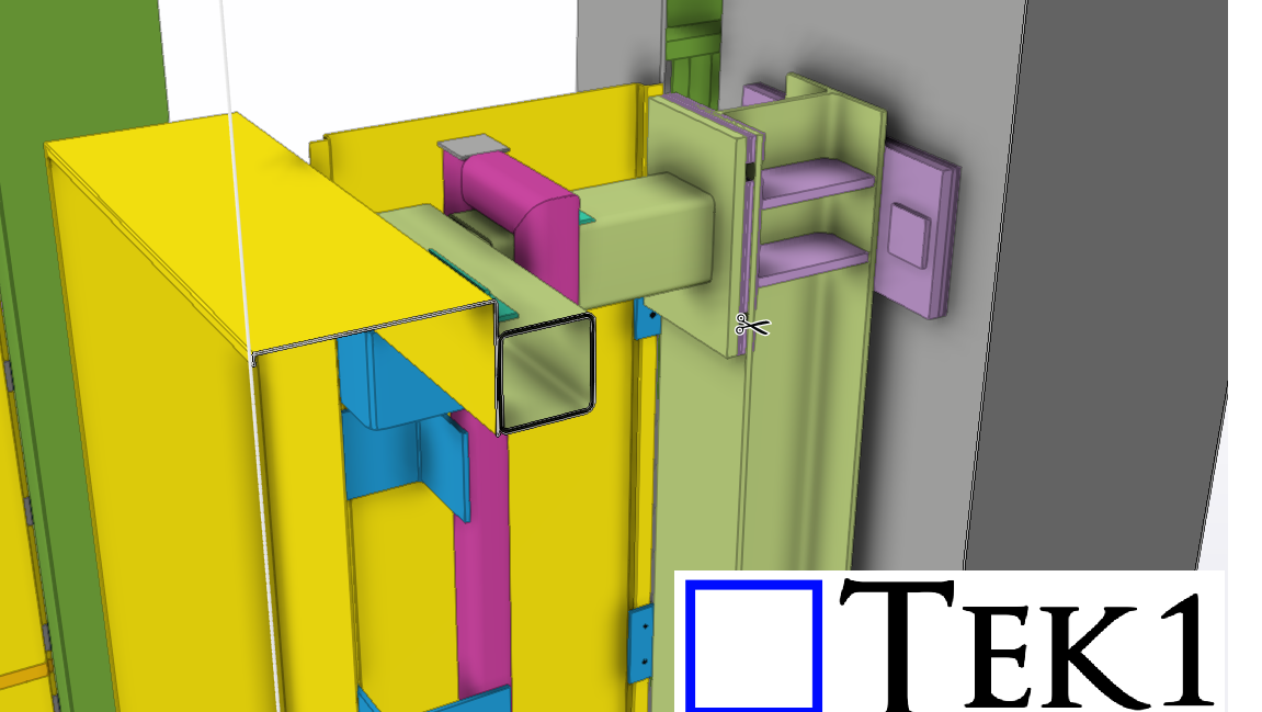
The engineer approved our detailing with minimal changes, which helped speed up the process and made things easier for the client. The use of different profile types also optimized the design for practicality and efficiency.