Category: Precast Blogs

Tek1 has detailed over 100,000 precast panels over 19 years.
over 90,000 were detailed under a proxy name Advanced Pretty Pictures Pty Ltd

PRECAST PANEL DETIAILING
EXPERT PRECAST PANEL DETIAILING
  • What is a lifter? What is a tail bar? Why are they required in precast panels? (Precast – Lifter Series: Part I)

    Precast panels are heavy.
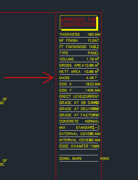
    Panel Mass
    Showing the title block of a shop drawing – shows the panel Mass.

    Cranes are used to lift the panels into place into their appropriate place. Because the mass involved is significant, it is very important that all the components of the lifting system are properly engineered and designed. If this is not the case then the panel could fall – and that can be lethal.

    In those post we will be focusing on lifters.

    This is how we denote a lifter:
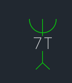
    Lifter symbol
    This is how we denote a lifter in shop drawings. The 7T lifter block.

    This is how a lifter anchor looks like in real life.
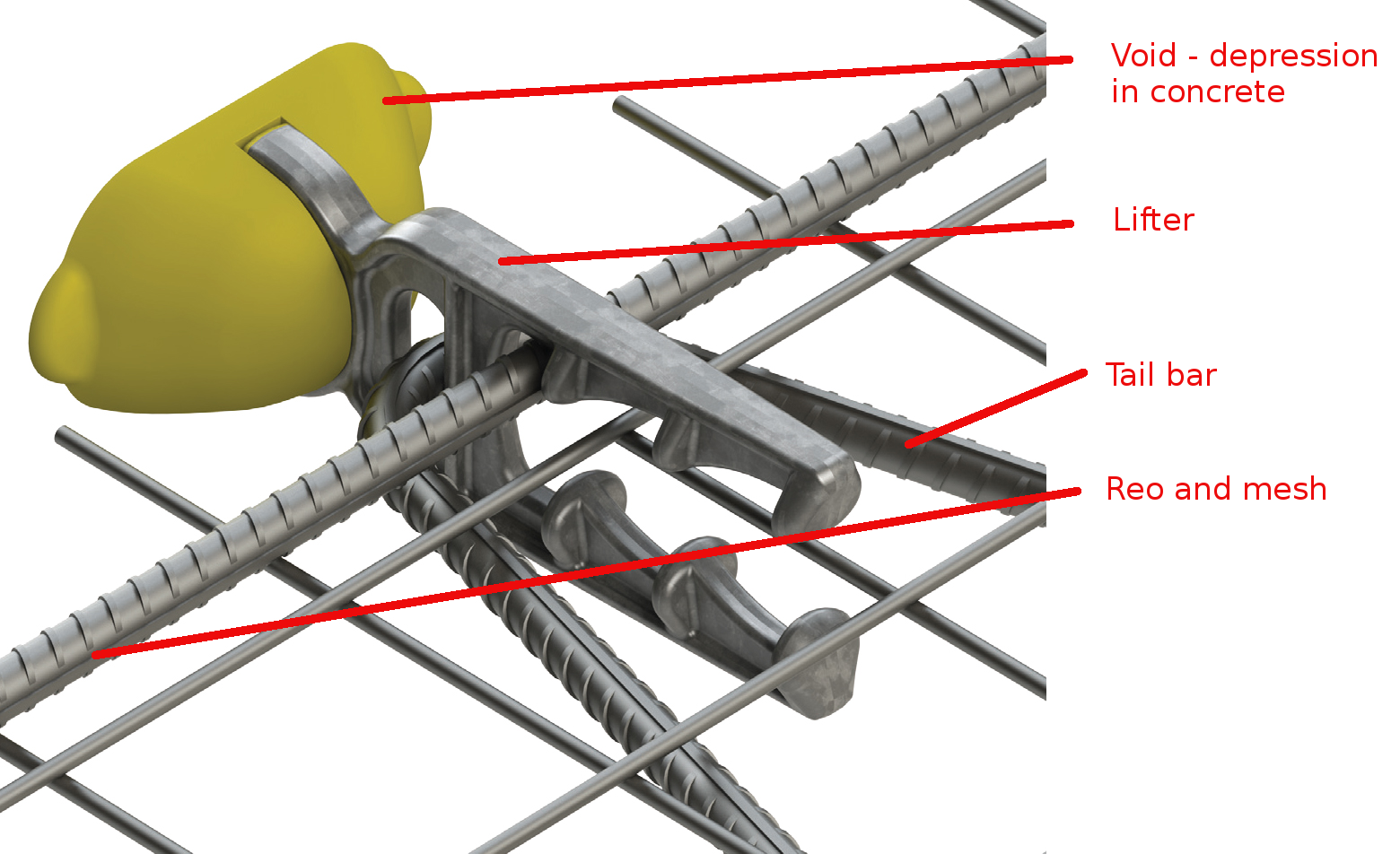
    Real Life Lifter
    Showing a lifter and all its composite elements: Reo, Tail bar, void, and mesh.

    Let us explain everything in detail – the purpose and what it does.

    1. The Void

    Precast panels are made in moulds. Items are placed in the mould and wet concrete is poured into it. The concrete is like water. You can’t have anything projecting out of the mould – everything must be contained within the mould itself. In other words, you need to provide a hook or latch onto the panel if you want to lift it. And the hook cannot project out of the panel because then it would be very hard to cast such a panel.
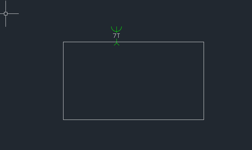
    Impractical panel design
    Shows a hypothetical panel with a protruding lifter. It would be difficult to fabricate this panel with the lifter within a mould, not to mention it being inconvenient.

    Imagine if someone fabricated the above panel – you will notice that the lifter is sticking out of the panel. This would be very hard to fabricate. Because it would require a hole to be exposed within the wet concrete for the lifter to protrude out from. Consequently, lifters are placed within the panel outline. And in order to facilitate the ability of a lifting system to latch onto the panel, a small depression and hook is provided within the panel. In reality, the panel will look something more like this:
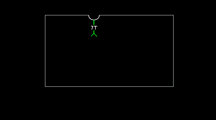
    A better representation of how a panel actually looks like
    This sketch more accurately represents how a panel is actually fabricated. You will notice a slight depression/void where the lifter is. A hook is located within that depression which is used to haul the panel up.

    You will notice that the actual concrete panel follows the white outline above, and that there is a depression in the panel. In addition – and this is not shown in the above diagram, there is a loop like feature on the end of the lifter which allows one to use it to haul the entire panel up into the sky etc. e.g. notice the hole at the top of the lifter shown below. It is this hole that is used to affix the lifter/panel to suspension systems.
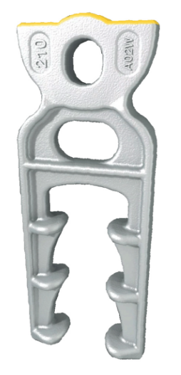
    Lifter Up close
    This shows you how a lifter actually looks like. There is a little bit involved in these things.
    1. The Tail bar and reo – it’s importance in the safety/stability of the lifting system

    The second thing to note in the above diagram is the tail bar and reo. Why is this important? It’s important if you want to be able to safely lift the panel. If you forget to add the tail bar and reo, and simply add a lifter without those items – then when you attempt to lift the panel, the concrete will simply break off where the lifter is and the panel will fall to the ground – potentially killing people under the panel as it is being hauled up.

    The tail bar and reo provide very important friction which ensures that the panel is safely secured to the lifter when it is in the concrete. Without it, the weight of the panel will simply cause it to separate from the lifter as it is being hauled up.

    Generally Tek1’s practice is to draw the lifter only. It is assumed to be standard factory knowledge that the tail bar should be added when the panel is cast. We make assumptions that the guys on the factory know what they are doing.

    1. Mesh

    The mesh is what gives the concrete some additional strength. It’s important.

    In tomorrow’s post we will more closely investigate the lifter and certain matters pertaining to lifting.
  • Demo: Select (Panel) Lines which are Open or Closed (Precast, AutoCAD .net)

    Demo of tool which selects closed lines.
    Demo of tool which selects closed lines.

    Sometimes we have a need to identify – and quickly – lines which are open and lines which are closed – especially prior to running any operations on those lines involving regions.

    Here is a demo of a little plugin I wrote.

    It goes through the modelspace and finds all the line segments which are connected to each other. It further goes on to query which line segments are closed and which are open.

    Getting AutoCAD to do this quickly was quite a task. But am very pleased with the speed – only 1-2 seconds when you’re iterating through a few thousand lines. Not bad.

    Enough talk, here is the demo:


    Select Open and/or Closed Panel Lines from Tek1 on Vimeo.


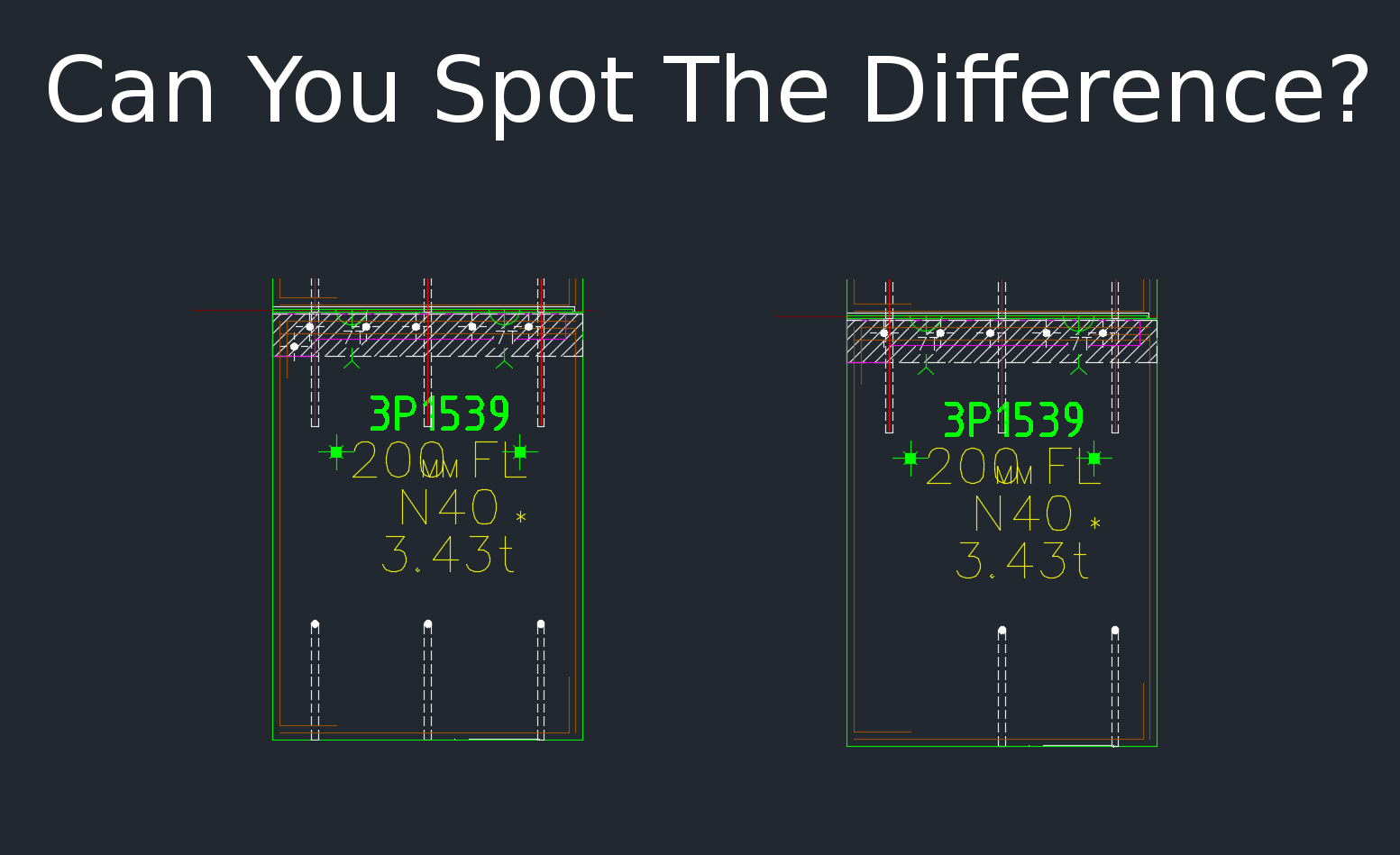
  • How to Easily Compare Precast Panels in AutoCAD (Precast)

    Drafting Services | Melbourne

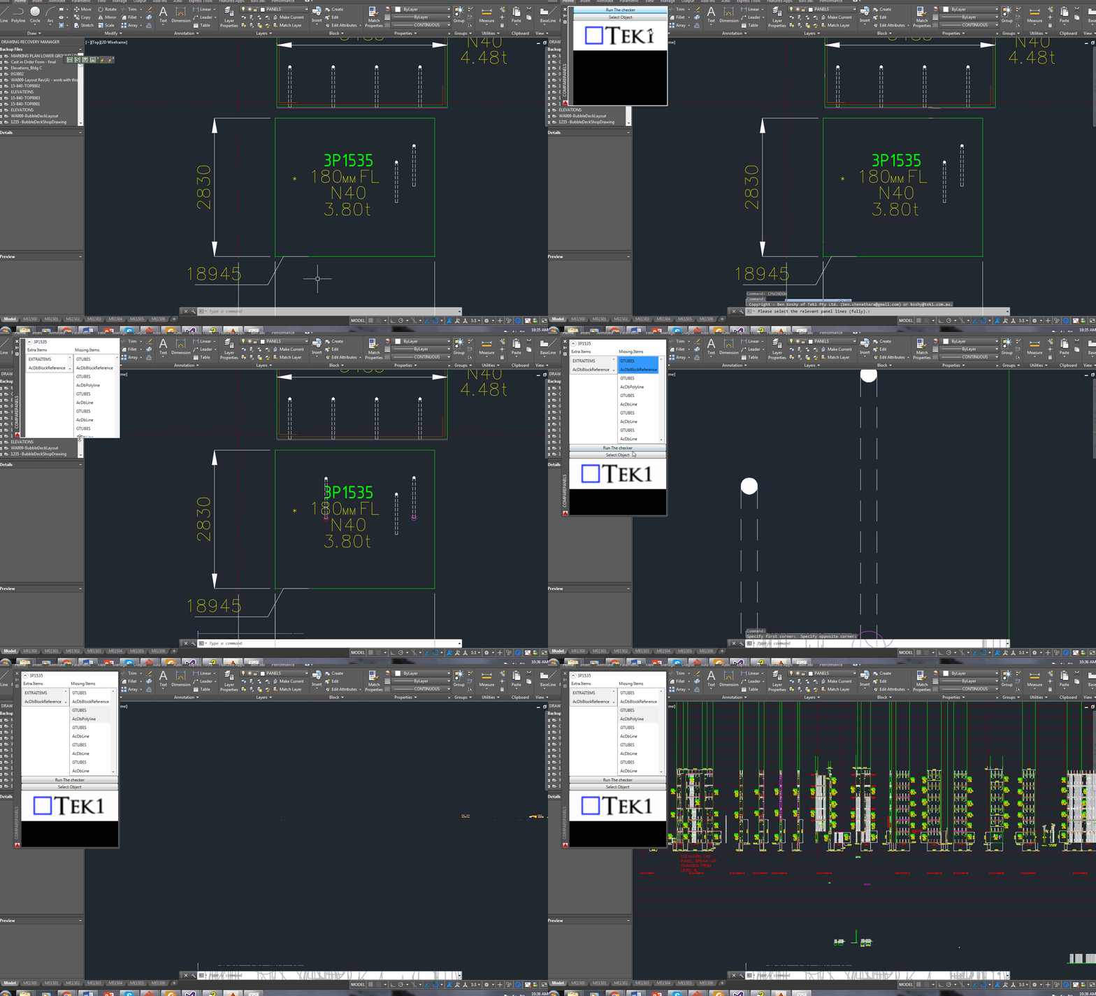
    When drafting for precast panels, there is need to check differences with different versions of the shop drawing. Manual checking a bit difficult. Automation tools help

    Panel Comparison Demo
    This tool compares panels and imports differences. Yet another reason why Tek1 is leading the world in precast panel drafting.
    Shop drawing / Layout panel discrepancies are a thing of the past.


    Suppose someone makes a change in the layout but forgets to do so in the shop drawing (and vice versa). If you move a cast in plate, and if it’s actually produced and taken to site, then you have a big problem, and a big cost. How are you going to identify the differences which exist in the thousands of panels that you make? What if you had a tool which allowed you to easily identify differences between the two drawings?

    This is what this Panel Comparison tool does. It gives you confidence that somebody hasn’t made a boo-boo. And moreover, if somebody has made one, then this tool identifies sloppy shop drawing practices.

    Here is the demo. I hope you enjoy it!

    Gif Demo with User Interface:

    Now we have a user interface which allows us to click on items in a window and access them easily in AutoCAD. Written by Ben Koshy.
    Now we have a user interface which allows us to click on items in a window and access them easily in AutoCAD. Written by Ben Koshy.

    Video Demo without a user interface:


    Compare Panels Demo – Import Panel Difference from the Shop Drawing to the Layout from Tek1 on Vimeo.

    Features:

    • It can work for all clients with only very minor modifications. Very well abstracted out in the code.
    • It is super fast. Comparing the thousands of elements in each drawing takes a bit of computing power – but with smart algorithms, you can cut down the time.
    • It works for all sorts of edge cases – what if the panel was made up of arcs, polylines and straight lines – this plugin can handle all sorts of things. It can also handle voids in the panel?
    • What if an item is on the edge of a panel line – it can handle that was well.

    Every single panel that we draw will go through the above practices. It should give you a lot of confidence that we’ll get the drawings right. Yet another tool in the Tek1 arsenal that allows this firm to lead the industry in Precast Panel drafting.


  • Demo – Create Revit Panels Directly From AutoCAD Panels (Precast)

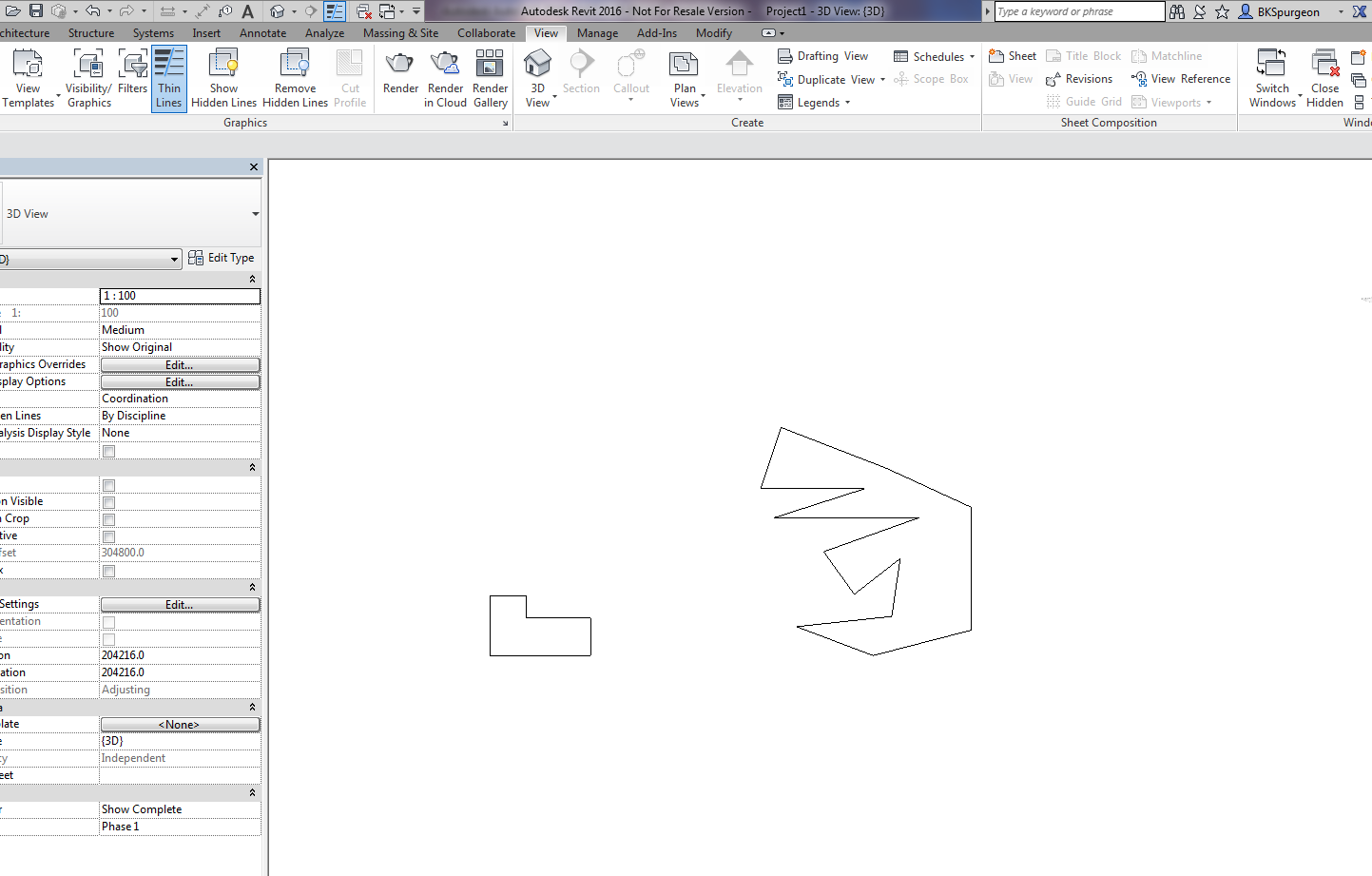
    Demonstrates the ability to transform 2D AutoCAD files into a native Revit format.

    This is a demo of my latest plug-in which demonstrates a proof of concept – i.e. a MVP (Minimum Viable Product). The programming was a little trickier than normal – because we are not using the .NET API, but the COM Interop API and the Revit API – something which I have not really explored prior to this post.

    What does it do?

    If you have drawn some panels in AutoCAD, this plugin allows you to quickly and accurately convert those panels into Native Revit walls. You can then give Architects and builders those Revit files –  otherwise it will be very difficult for them to work with AutoCAD files.

    This gives you a competitive advantage over your competition, because you can quickly and easily do it – and it makes the job of architects and builders easier – especially given the rapid push everyone’s making into BIM technologies.

    Enough talk. Here is the demo. Enjoy:

    Create Panel Walls in Revit Directly From AutoCAD – Demo from Tek1 on Vimeo.

    (I’ve made the command so that it works even when you have AutoCAD open. This allows detailers to quickly switch to Revit and AutoCAD and to delete and restart if need be. Also requiring that AutoCAD be open ensure that detailers know exactly what file they are working with and what files they are converting. It eliminates a whole lot of errors.)

  • The Curious Case of Overkill Not Working (AutoCAD)

    A very perplexing question:

    Why isn’t overkill working?

    The result will stun you.

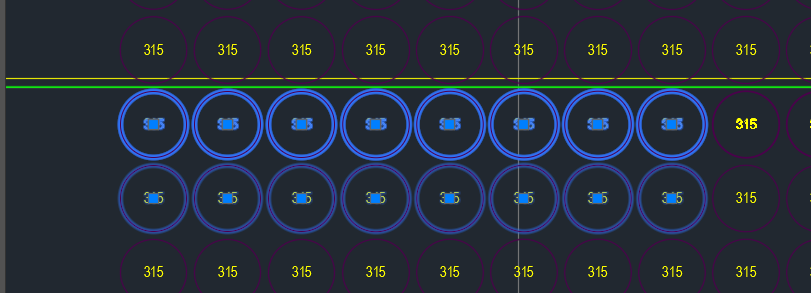
    Overkill was not working
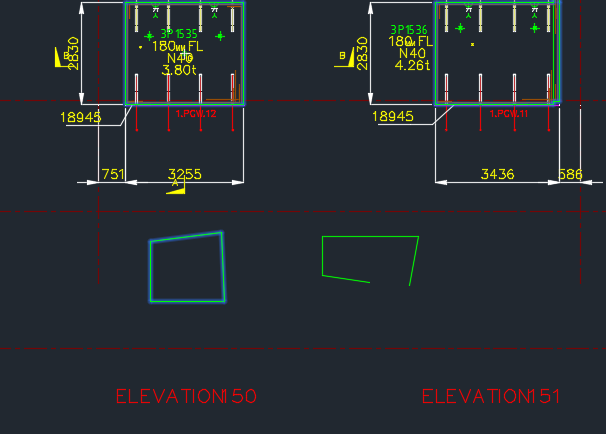
    Overkill command was not working on these panel voids. Why do you think this is the case?

    As you can see in the above picture, the top row of panel voids were doubled and in some cases tripled up. Obviously we don’t want this. Ordinarily, when such drawings are passed on to us we employ the overkill command. But for some reason it wasn’t working. And I couldn’t for the life of me figure it out.

    That was until our lead Bubble Deck detailer suggested that the insertion points of the block references were not all on the same plane – some of them were in the Z plan – if that’s the case, then overkill would not recognise them as being the same block – and will allow them to continue to co-exist in the same drawing.

    Solution:

    Check that all similar items have similar insertion points. If they’re different – that’s why overkill might not be working for you.

  • Dimensioning Curves Using Jigs (AutoCAD .net, Precast)

    This is a beautiful little plug-in – it allows you to dimension a curve – a complex curve with a jig. It allows the user to choose the types of dimensions that he wants. It’s pretty cool.

    I must do an entire series on jigs.

    And I will slowly, when I get the chance.

  • Tek1 Tools – Panel Comparisons (Precast)

    Demo – Tool To Compare Panels and Easily Identify Differences

    Here’s the situation:

    Someone from the factory floor calls in:

    “Hey can you move a cast in plate across panel number ABC123”

    “Sure – let me just check there are no —”

    “GIVE ME THE DRAWINGS NOW!”

    The problem with handing over the drawings without checking the layout is that you might make a big mistake! Or you might forget to ensure the two drawings link up and are the same.

    You need a tool to easily check the panels, identify differences and to alert the detailer. This will also allow you to easily split up work. – you can assign that work to a junior detailer, so he/she gains experience, while it frees up time for you to focus on other things.

    And if you do find a difference, it’s a big ordeal brining the layout up to speed. With this program, it automatically imports the pertinent block/polyline etc. without you lifting a finger.

    The advantages are many. The simplicity is sublime. Enough talk.

    Here’s the demo of the tool. I hope you enjoy it.

    This tool currently works for only Bubble Deck. But I am going to make it work for all clients across a variety of edge cases and am going to speed up the algorithm considerably. I will post the new tool when it is completed.

    Panel Comparison – Tek1 Tools from Tek1 on Vimeo.

  • Stair Outline Routine (AutoCAD .net + Code attached)

    An example of the type of stairs we draw. We do a lot of stairs. Both AS 1428 and AS 1657 compliant stairs.
    An example of the type of stairs we draw. We do a lot of stairs. Both AS 1428 and AS 1657 compliant stairs.


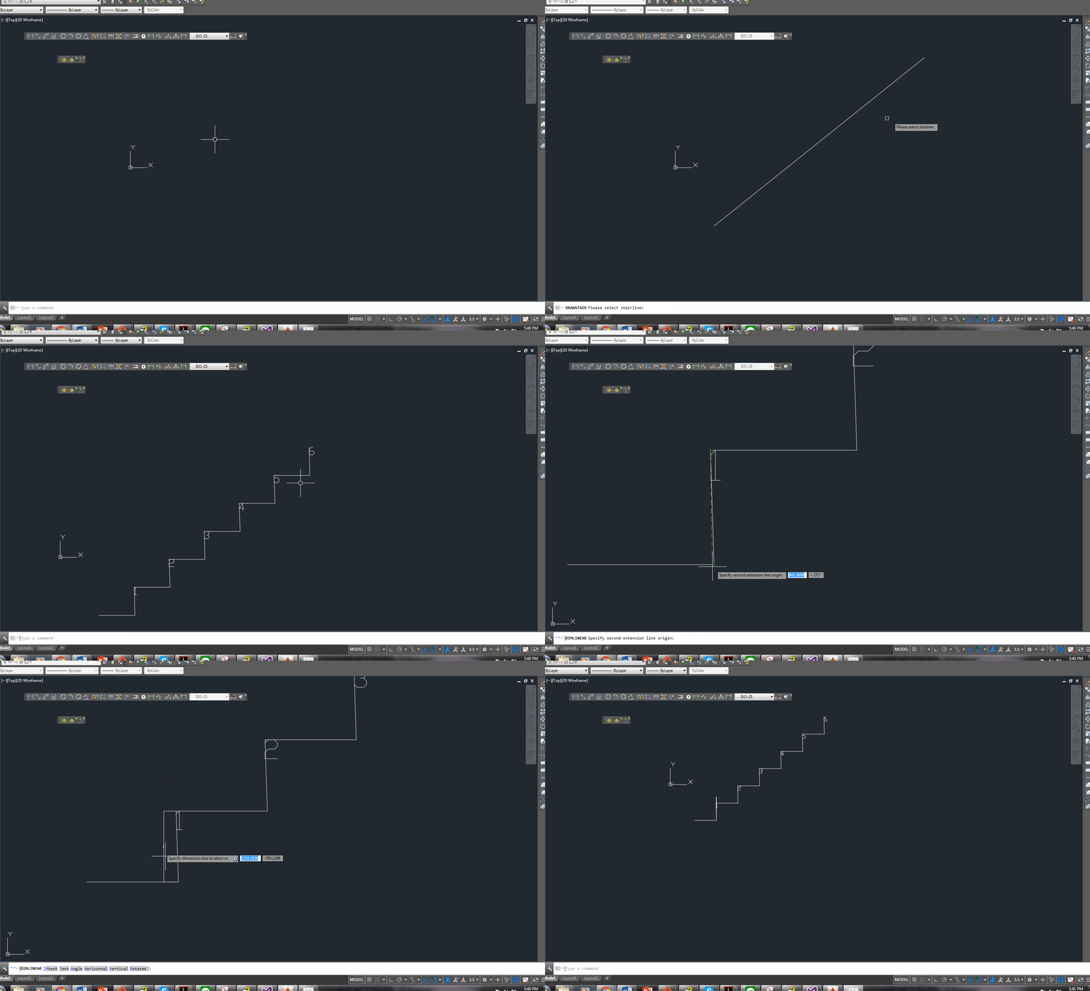
    We continue delving into our discussion of stairs. The boss hates it when I do things like this – releasing code to the public. But it’s too good not to share. Below is a routine you might find useful. We use it to model stairs – it’s super fast, and efficient. It allows us to try different things out and to discard what doesn’t work with ease. I’ve gone to the effort of drawing up an entire flight of stairs and then realised that I’m missing a tread. Then I’d have to redo the whole thing from the beginning. Once you have this outline done, the a good chunk of the work is finished.

    One of our many, many versatile routines:

    Here is a gif of the project:

    A Stair AutoCAD Plugin
    A plugin I wrote for AutoCAD. Written using c#.

    And here is the code for the benefit of study.

    I suppose I should refactor it, but I don’t think I’ll be changing it any time soon. So why worry?

  • Tekla–AutoCAD: Interoperability Tool

    Tekla – AutoCAD Interoperability Tool

    Tekla licenses are pricey. About $30k + maintenance per license. That’s expensive. And if you had 10 licenses, or perhaps even 50 licenses, what if I told you that you needed: 30-50% less licenses than you currently hold? That’s a huge cost saving. If you only need 5 licenses, then you’ve saved $150k instantly, plus maintenance. You can now do that.

    AutoCAD licenses are significantly cheaper than Tekla.

    But if only the work you did in AutoCAD could be transferred into Tekla? That would save you some licenses.

    That’s just what I’ve done here in my latest project. You can check it out here:

    Tekla – Autocad Interop. from Tek1 on Vimeo.

    Thanks for visiting this page.