Category: Precast Blogs

Tek1 has detailed over 100,000 precast panels over 19 years.
over 90,000 were detailed under a proxy name Advanced Pretty Pictures Pty Ltd

PRECAST PANEL DETIAILING
EXPERT PRECAST PANEL DETIAILING
  • Checking the Transportability of Precast Panels – Using the AutoCAD .net API

    Checking the Transportability of Panels – Using the AutoCAD .net API

    It is one thing to build a panel. It is another to ensure that:

    1. It can be lifted, and
    2. It can be transported to the site.

    Here is a video demo explaining everything:

    Can a precast panel be safely transported? from Tek1 on Vimeo.

    A short primer on the importance of efficiency

    When you are dealing with 100s, and perhaps even up to a 1000 panels per building, this can become extremely cumbersome and time consuming. Why not automate the entire process? This allows you to do things faster, to get the drawings out faster, and (hopefully) to build the panels faster, and ultimately the building faster. Speed is absolutely paramount! The faster a builder can get on and off of a construction site, the faster they can get paid. This lowers their working capital needs, and accordingly, their financing costs (however that may arise). Speed is king!

    Considerations When Transporting Panels to Site

    Every truck has a:

    • Size limitation (both length and height), as well as a:
    • Weight limitation (there is a maximum capacity).

    Secondly, trucks have different limitations, depending on where they are transporting a panel. E.g.

    • Trucks passing through the CBD (central business district) have different: length/height and mass requirements compared to those that are not, furthermore, these requirements are different depending on whether the truck has a permit or not.

    Let’s suppose you have the following hypothetical situation – take out a sheet of paper and pen and try and solve this by hand:


    Truck A

    • Length limitation: 6 m
    • Height limitation: 3 m (but a height limit of 2.5 m in the CBD; and a height limit of 3.2 m with a permit)
    • Weight Limit: 12 tonnes.


    Truck B

    • Length limitation: 4 m
    • Height limitation: 4 m (but a height limit of 2.5 m in the CBD; and a height limit of 3.2 m with a permit)
    • Weight Limit: 18 tonnes.


    How on earth are you going to work out, quickly and efficiently, whether your fleet can transport the following panels:

    1. ABC1 – Mass: 13 tonnes, Length: 5 m, Height 3 m
    2. ABC2 – Mass: 10 tonnes, Length: 3 m, Height 2 m
    3. ABC3 – Mass: 12 tonnes, Length: 4 m, Height 2.5 m


    Problem

    • Are you able to transport your panels by any of the trucks in your fleet?
    • Which of your trucks can you use to safely transport a particular panel?

    How was this particular problem was solved using the AutoCAD .net API?

    • I created a data structure for each of the limitations imposed by a truck.
    • Similarly, I created a data structure for each of the limitations imposed by each panel.
    • And very simply asked whether a truck and lift a panel? The output was compiled and put into an Excel report. They key method tying this all together is the `CanLift` method on the Truck class.
    • I used ClosedXML to combine it all together to produce a report.

    Here is an example of the results:
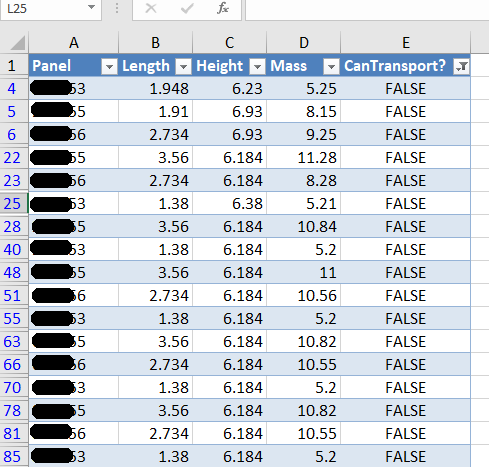
    panels that failed the transport check
    A sample of the report produced when running the command. This is showing all the panels that failed.

    Here are the key server classes:

    Summary

    • Tek1 has the resources and expertise in order to do Precast Panelling jobs fast and
    • Accurately

    These are just the tip of the ice burg in terms of the checks and processes we employ.

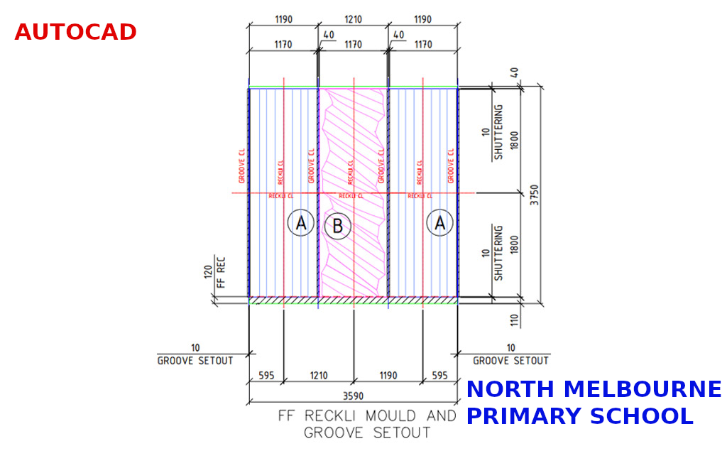
  • Should you cast in a Reckli Groove in a precast concrete panel?

    There are situations where you may prefer to cast in a Reckli groove.

    If the Reckli is contained within one panel, then you must surely cast it in. However, if the flashing groove runs past several panels, it may be better to saw cut the groove at site.

  • Jigging with SHIFT, CTRL and Mouse Wheel Functionality (AutoCAD .net API)

    If writing software then make it easy for your users.
    User Input is critical. You gotta make the user experience amazing.

    Any AutoCAD programmer knows that things which an algorithm may take a million years and infinite computational power to do can sometimes be easily done by a human being instantly. In the same way it is sometimes much easier to give a human being the ability to choose: then you can get an optimum result without complex algorithms.

    This post is a code snipped of how you can utilise the CTRL + SHIFT + Mouse Wheel (up/down) mechanisms in order to produce different desired results when operating a custom jig.

    Here is the code:


    So when the appropriate user input happens, then the jig can respond accordingly. Yes it’s true – the OOP purists will say: “you’re passing a concrete type in there” – I can always change it later if I want.

  • Offsetting Truss Lines from Intersecting Fire Collars (Bubble Deck + Video Demo)

    The effective point of this blog is to demonstrate the use of a jig – not just any old jig – but a jig which accepts user inputs using the CTRL + SHIFT + MOUSE-WHEEL (up or down) to change the jig’s behaviour. When the jig is finished running, everything returns back to normal.

    This is best demonstrated with a video:

    Move Intersecting Truss by Panel Thickness (with Jig) from Tek1 on Vimeo.

    We use this jig and command as part of our Bubble Deck tools dll.

    The reason we utilise tools like this:

    This allows us to turn over shop drawings faster, more efficiently. This allows our precast fabricator to massively improve their working capital position:

    • Their factory staff is always utilised – they don’t have massive overheads of 50 guys sitting on the factory floor twiddling their thumbs,
    • They can get in and out of jobs quickly – minimising their liabilities and expenses and also collecting revenues faster,
    • Faster revenue has huge benefits in terms of interest saved vs interest earned – especially for the developer. If you can allow the developer to finish the job a couple of weeks earlier you save on: construction costs, and also, as before, their interest expenses and their liquidity also improves. That’s worth its weight in gold.
    • There is nothing worth more than: accurate drawings, done quickly. That’s what we strive for.
  • Speed up the Shop Drawing Process – Order Dimensioning Tool (Bubble Deck)

    Dimensions are critical
    A nice photo of a scale.

    I’ve made a tool which allows you to order dimensions faster.


    Here it is below:

    Order Dimension Command from Tek1 on Vimeo.


    For those who want to read my philosophy of the benefits of improving productivity and how I approach detailing – see below. If that bores you, then you may safely skip it with no loss.

    An Approach to Detailing: Make things Easier and make them faster

    Productivity is what makes the world go round faster. It’s why you can fly from Melbourne to London in less than 24 hours. 500 years ago it might take you a few months – and that too at a break neck speed. Today, anything over 2 days is a painful delay.

    Improving Shop Drawing Productivity

    It’s the same with shop drawings. We found that our detailers were spending too much time ordering dimensions. That’s something that can be sped up. We want to smash something which had taken over an hour down to 5-10 minutes. And if possible, we want to reduce that time to zero. This allows our detailers to turn around shop drawings quickly to their Precaster – which will in turn massively improve the Precasters turn around time, and working capital situation, and will allow a continual throughput of panels being cast on the factory floor. In other words you will never have a situation where you have 30 guys on the shop floor twiddling their thumbs because their drawings weren’t brought to them quick enough. And if you can get out of a project earlier, that means you can get paid earlier. That in term will allow developers to quickly build and get out of a project ASAP, which would have monumental impacts to their working capital positions and overall profitability. In short, doing things quickly and accurately is worth a lot………………..Time is money.

    Small improvements have big impacts.

    That’s how I approach detailing.


  • The Connect Handrail Command – Demo (BubbleDeck)

    A lovely picture of handrails.
    A lovely picture of handrails.

    This is a little utility which connect handrails. It does so if:

    1. The handrail block references are parallel to the panel edges, and
    2. If they are a minimum 560 mm away from the edges and
    3. If they are colinear with each other.

    Here is a demo:

    Demo – Connect Handrails Command in AutoCAD` from Tek1 on Vimeo.

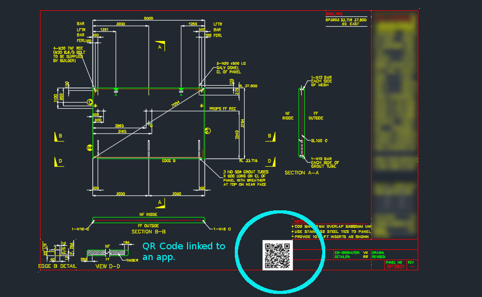
  • Tek1 Adds QR Codes to Drawings backed by an App on the cloud

    Clear lines of communication is one of the keys to the success of any organisation.

    Now you can easily track and record information pertaining to panels with a QR code on each panel drawing.

    Here’s how it works:

    • You scan the QR code, if you’re on the construction site and want to find out specific information about the panel, or if you want to record information about the panel.
    • Everything is backed by an app on the web.

    In this case, we can record things like:

    • panel status
    • drafting issues/errors – pertaining to a panel (so the entire drafting process can be improved).

    Once the status is recorded, or issues are raised, this is tracked and recorded by the app.

    The basic point is that it is very difficult to track and record information pertaining to a panel throughout the entire organisation. Not anymore!


    You scan the QR code, if you’re on the construction site and want to find out specific information about the panel, or if you want to record information about the panel.
    Now you can record and communicate panel specific information to everyone in the organisation.
  • Create Truss (Process) – BubbleDeck Detailing

    Not a truss, but it looks good.
    Not a truss, but it looks good.

    A nifty little tool that automatically inserts trusses into bubble deck panels depending on:

    • Their thickness
    • their width

    And also their:

    • specified ball / void spacing.

    Please remember to select all the panel lines.

    You can see a video demo here:

    Create Truss – Tek1 Tools for BubbleDeck from Tek1 on Vimeo.

  • Drawing Metal Edges – BubbleDeck Detailing (+ Video Demo)


    Drawing these metal edges is time consuming and error prone.
    Drawing these metal edges is time consuming and error prone.


    What is the task at hand?

    You have a set of 30 panels. You need to draw metal edges around the edges of all these panels. That’s easy, but it’s subject to certain specific requirements.


    If it’s a Perth job then:

    • The metal edge can only be a maximum of 3.0m long.
    • Minimum distance: 0.4m long.


    If it’s an Adelaide job these are the metal edge requirements:

    • The metal edge can only be a maximum of 2.4m long.
    • Minimum distance: 0.4m long.

    That means you may need to do some maths. And you actually have to draw the things in. It’s a royal pain, and more than likely, you’ll make mistakes.


    Video Demonstration of the Draw Metal Edges Tool

    This tool obviates the need for manual calculations and drawing by hand. Chances of pick point errors and wrongly stipulating an unmakable and unorderable metal edge is there by significantly diminished.


    Here is a video demonstration:


    Draw Metal Edges from Tek1 on Vimeo.